EP0641630A1 - Procédé et dispositif pour la surveillance et l'enregistrement des phases de travail de machines à couper du papier - Google Patents
Procédé et dispositif pour la surveillance et l'enregistrement des phases de travail de machines à couper du papier Download PDFInfo
- Publication number
- EP0641630A1 EP0641630A1 EP94112794A EP94112794A EP0641630A1 EP 0641630 A1 EP0641630 A1 EP 0641630A1 EP 94112794 A EP94112794 A EP 94112794A EP 94112794 A EP94112794 A EP 94112794A EP 0641630 A1 EP0641630 A1 EP 0641630A1
- Authority
- EP
- European Patent Office
- Prior art keywords
- saddle
- saddle position
- time
- machines
- coordinates
- Prior art date
- Legal status (The legal status is an assumption and is not a legal conclusion. Google has not performed a legal analysis and makes no representation as to the accuracy of the status listed.)
- Ceased
Links
Images

Classifications
-
- G—PHYSICS
- G05—CONTROLLING; REGULATING
- G05B—CONTROL OR REGULATING SYSTEMS IN GENERAL; FUNCTIONAL ELEMENTS OF SUCH SYSTEMS; MONITORING OR TESTING ARRANGEMENTS FOR SUCH SYSTEMS OR ELEMENTS
- G05B19/00—Program-control systems
- G05B19/02—Program-control systems electric
- G05B19/418—Total factory control, i.e. centrally controlling a plurality of machines, e.g. direct or distributed numerical control [DNC], flexible manufacturing systems [FMS], integrated manufacturing systems [IMS] or computer integrated manufacturing [CIM]
- G05B19/4184—Total factory control, i.e. centrally controlling a plurality of machines, e.g. direct or distributed numerical control [DNC], flexible manufacturing systems [FMS], integrated manufacturing systems [IMS] or computer integrated manufacturing [CIM] characterised by fault tolerance, reliability of production system
-
- B—PERFORMING OPERATIONS; TRANSPORTING
- B26—HAND CUTTING TOOLS; CUTTING; SEVERING
- B26D—CUTTING; DETAILS COMMON TO MACHINES FOR PERFORATING, PUNCHING, CUTTING-OUT, STAMPING-OUT OR SEVERING
- B26D5/00—Arrangements for operating and controlling machines or devices for cutting, cutting-out, stamping-out, punching, perforating, or severing by means other than cutting
-
- Y—GENERAL TAGGING OF NEW TECHNOLOGICAL DEVELOPMENTS; GENERAL TAGGING OF CROSS-SECTIONAL TECHNOLOGIES SPANNING OVER SEVERAL SECTIONS OF THE IPC; TECHNICAL SUBJECTS COVERED BY FORMER USPC CROSS-REFERENCE ART COLLECTIONS [XRACs] AND DIGESTS
- Y02—TECHNOLOGIES OR APPLICATIONS FOR MITIGATION OR ADAPTATION AGAINST CLIMATE CHANGE
- Y02P—CLIMATE CHANGE MITIGATION TECHNOLOGIES IN THE PRODUCTION OR PROCESSING OF GOODS
- Y02P90/00—Enabling technologies with a potential contribution to greenhouse gas [GHG] emissions mitigation
- Y02P90/02—Total factory control, e.g. smart factories, flexible manufacturing systems [FMS] or integrated manufacturing systems [IMS]
Definitions
- the present invention relates to a method and an apparatus for monitoring and registering the workflow on one or more paper handling and cutting machines, such machines having at least one saddle for have the feed of a paper giant and the saddle position is also detected by a measuring or sensor device and fed to a data processing station.
- the present invention has therefore set itself the goal of creating a method and a device with the features mentioned at the outset, which enable the operator at any time to obtain an overview of the current status, of those which have already been completed and still to be completed, in a simple and descriptive manner To provide work steps in order to be able to intervene if necessary and for example to carry out further, improved planning and, in particular, to optimize the control program of the machine.
- this object is achieved in that the saddle position is assigned to one of these coordinates in an at least two-dimensional coordinate system, while another coordinate is assigned to time, and an image resulting from these coordinates is on an essentially flat image surface, such as for example a screen or a paper web.
- the time coordinate and the saddle position coordinate only as a dot (i.e. on a screen as a luminous dot or as an ink dot on the paper web of a time recorder).
- a vector representation would also be possible, with the aid of a vector which starts from the coordinate origin and ends at the end point defined by the coordinates.
- a change in the saddle position is characterized by a straight line which corresponds to the vector component of the saddle position, namely as a line which, at a fixed point in time, that is to say perpendicular to the time axis, extends from the time axis or "zero line" to the saddle position coordinate extends.
- a zero point suppression can also be provided, ie the "zero line” is replaced by a line parallel to the time axis.
- the time coordinate at which the line lies corresponds, for example, to a point in time which is defined by the fact that within a predeterminable time interval there has been no measurable displacement or at most a displacement of the saddle position which is also below a predefinable threshold value, whereas in a preceding one, corresponding shift in time, a shift was still noticeable.
- the saddle position can also be represented by such a line at a point in time at which the saddle transitions from a rest position to a changing state of motion.
- a corresponding point in time of the transition from a displacement movement of the saddle to the idle state and vice versa can be defined, for example, by considering two adjacent time intervals of a predeterminable length, the representation of the saddle position using the vector component of the saddle position being determined in that during one No measurable change in the saddle position has occurred in the time interval, whereas in the adjacent time interval such a change in saddle position has taken place.
- the start and end of the shift of the saddle position can be determined and each marked by a line running perpendicular to the time axis, whose length corresponds to the current saddle position.
- a variant of the invention is preferred in which a cutting process is reproduced as a line running parallel to the time axis at a fixed saddle position, the line in question starting from the coordinate point of the fixed saddle position before the start of the cut, the length of this line being parallel to the time axis corresponds exactly to the duration of the cut.
- the saddle position is represented by a line perpendicular to the time axis, which extends from the zero line to the saddle position coordinate.
- the criterion for the display of such a line can in turn be selected analogously to the detection of the beginning and end of the saddle movement, in that a movement of a cutting knife is determined by comparing position measurements in adjacent time intervals.
- movements of the cutting system can also be determined simply by means of light barriers or touch contacts, but this does not trigger the display of a knife position, but instead the display of the current saddle position plus the "cutting line" parallel to the time axis, as described above.
- a change in the saddle position is preferably also reflected by a course of the saddle position as a trace of the coordinate time and saddle position.
- a variant of this method is simpler and less memory-consuming, in which only the coordinates of the start and end point of the saddle position are recorded in the two-dimensional path-time plane, these two end points being connected to one another only by a straight line.
- a variant of the invention is preferred, in which such information about additional work steps can be displayed separately on a display screen in a window that can be opened optionally.
- the present invention can be used particularly advantageously if a plurality of machines are connected to one, or possibly also a plurality of, data processing systems at the same time, the workflow on each of the machines either being shown separately on different screens, or a screen being able to be switched over to optionally display the workflow on any of the machines on this screen. It can further be provided that the work processes of several machines are displayed simultaneously one above the other or in a perspective representation nested one behind the other. Even when using a multi-channel time recorder, the work processes on several different machines are displayed simultaneously.
- An embodiment of the invention is particularly preferred in which the data required for the representations mentioned above are stored, preferably in compressed form, that is to say in the case of storing straight lines simply by storing the start and end points of the lines with the additional information, that these end points are to be connected by a line.
- the object on which the invention is based is achieved in an analogous manner in that a display device is provided for the graphic display of the saddle position over time.
- “playback device” does not only mean a visual display device, such as a screen or a time recorder, but also the associated program, which only converts the workflow into a corresponding graphic representation.
- the device according to the invention also has devices which record and register the start and end of a cutting process and also devices which record the start and end of a displacement and / or Record and register the twisting process of the saddle of a machine.
- Such devices can be implemented using both hardware and software and are generally combinations of both elements.
- the start and end of the displacement of the saddle can be detected by sensors that monitor the power supply to a corresponding displacement motor.
- the start and end of a shifting process can also be recorded by software, for example using the method already described above, in each case by considering short, adjacent time intervals, with the start or end of a change in position of the saddle is defined by the fact that in one time interval there is a measurable shift in the saddle position, while in the other interval there is no such measurable change in position.
- the device for recording the start and end of a shifting process represents a combination of hardware and software elements.
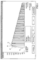
- the attached graphic corresponds to a so-called screen mask, which is displayed either in black and white or in color on a screen and can only be displayed here in black lines on a white background.
- a coordinate system can be seen which indicates a saddle position in arbitrary units (for example centimeters) in the vertical direction, while the time is shown on the horizontal axis.
- the total time period shown comprises a period of just under two minutes according to the start and end dates specified simultaneously.
- a vertical line V can be seen at the beginning, which corresponds to the time at which the saddle position begins to change from a point corresponding to a scale value of approximately 25, towards a larger scale value of approximately 120.
- This displacement of the saddle lasts a few seconds and is shown as a relatively steeply rising line P at the left end of the diagram.
- the end of the displacement of the saddle and its position are in turn marked by a vertical line that marks the end point of the displacement process on the time axis and whose length corresponds to the current saddle position. Then you can see a gap or break A, which is used, for example, for a tool change.
- a renewed vertical line marks the saddle position at the beginning of a cutting process, the cutting process itself being reproduced as a horizontal line S, which begins at the current saddle position and also ends at the same position and whose length corresponds to the duration of the cutting process.
- the saddle then shifts somewhat towards smaller scale values, with the start and end points in turn being marked by vertical lines with the length of the current saddle position.
- There is again a short pause and then another cut which in this example is somewhat shorter in time than the first cut, whereupon the saddle position is changed, another cut and the saddle position is changed again before there is a short pause.
- this concrete diagram does not correspond to a typical workflow, which generally results in a much more complex picture (also called a signature).
- the beginning and end of cutting processes and also the beginning and end of the change in saddle positions are each defined by a vertical line which represents exactly this point in time of the beginning or end, with cutting processes additionally being represented by their time course as horizontal lines, since of course the saddle position does not change.
- the diagram shown could also be represented only as an outline diagram and that it is not necessary to mark the beginning and end of the cutting and displacement processes in each case by vertical lines.
- the beginning and end could also be marked by changing the color, so that the areas delimited here by vertical lines would then appear as bars or columns. Such colored representations would also facilitate the recognition of breaks and are within the scope of the present invention.
- FIG 2 one can see the sequence of a twice repeating and in this case more realistic cutting program.
- the cutting program begins with a cut S1, followed by a position shift P1 and a waiting or changeover time A, which in turn is followed by a cutting process S2.
- the further changes in position and cutting processes, which are not specifically described, are still interrupted by waiting or changeover times B and C. Shorter breaks are not explicitly marked.
- D is again a time period that marks the preparation time for a repetition of the same cutting program on a new paper giant. This also includes shifting the saddle position to the initial value for section S1.
Landscapes
- Engineering & Computer Science (AREA)
- General Engineering & Computer Science (AREA)
- Manufacturing & Machinery (AREA)
- Quality & Reliability (AREA)
- Physics & Mathematics (AREA)
- General Physics & Mathematics (AREA)
- Automation & Control Theory (AREA)
- Life Sciences & Earth Sciences (AREA)
- Forests & Forestry (AREA)
- Mechanical Engineering (AREA)
- General Factory Administration (AREA)
- Numerical Control (AREA)
Applications Claiming Priority (2)
| Application Number | Priority Date | Filing Date | Title |
|---|---|---|---|
| DE4329883 | 1993-09-06 | ||
| DE4329883A DE4329883A1 (de) | 1993-09-06 | 1993-09-06 | Verfahren und Vorrichtung zur Überwachung und Registrierung der Arbeitsabläufe an Papierschneidemaschinen |
Publications (1)
| Publication Number | Publication Date |
|---|---|
| EP0641630A1 true EP0641630A1 (fr) | 1995-03-08 |
Family
ID=6496817
Family Applications (1)
| Application Number | Title | Priority Date | Filing Date |
|---|---|---|---|
| EP94112794A Ceased EP0641630A1 (fr) | 1993-09-06 | 1994-08-17 | Procédé et dispositif pour la surveillance et l'enregistrement des phases de travail de machines à couper du papier |
Country Status (3)
| Country | Link |
|---|---|
| EP (1) | EP0641630A1 (fr) |
| JP (1) | JPH0776000A (fr) |
| DE (1) | DE4329883A1 (fr) |
Cited By (3)
| Publication number | Priority date | Publication date | Assignee | Title |
|---|---|---|---|---|
| EP0740983A1 (fr) * | 1995-05-04 | 1996-11-06 | Wohlenberg Vertriebs- und Service GmbH | Machine pour le découpage sur trois cÔtés |
| EP0829332A1 (fr) * | 1996-09-12 | 1998-03-18 | Adolf Mohr Maschinenfabrik GmbH & Co. KG | Dispositif pour la coupe de matériau en feuille |
| WO1998038018A1 (fr) * | 1997-02-28 | 1998-09-03 | Perfecta Schneidemaschinenwerk Gmbh | Procede et dispositif pour rogner un ensemble de papiers ou d'elements empilables constitues d'un materiau semblable a du papier |
Families Citing this family (1)
| Publication number | Priority date | Publication date | Assignee | Title |
|---|---|---|---|---|
| JP6806070B2 (ja) * | 2015-09-28 | 2021-01-06 | 富士通株式会社 | 管理システム、管理方法および管理プログラム |
Citations (5)
| Publication number | Priority date | Publication date | Assignee | Title |
|---|---|---|---|---|
| DE2138111A1 (de) * | 1971-07-30 | 1973-02-08 | Rudolf Mohr | Elektronische massanzeige fuer papierschneidemaschinen |
| DE2752418A1 (de) * | 1977-11-24 | 1978-12-07 | Schneiderwerk Luebeck | Schneidemaschine zum schneiden von papier, pappen u.dgl. materialien |
| EP0182515A2 (fr) * | 1984-11-19 | 1986-05-28 | Franc Gergek | Commande pour massicots |
| AT393366B (de) * | 1983-03-01 | 1991-10-10 | Valmet Paper Machinery Inc | Verfahren und vorrichtung zur bestimmung der genauen position einer einrichtung zum schneiden einer bewegten materialbahn |
| US5131301A (en) * | 1989-04-07 | 1992-07-21 | Franc Gergek | Paper cutting machine |
Family Cites Families (1)
| Publication number | Priority date | Publication date | Assignee | Title |
|---|---|---|---|---|
| DE8604773U1 (de) * | 1986-02-22 | 1986-05-07 | H. Wohlenberg KG GmbH & Co., 3000 Hannover | Rechnergesteuerte Papierschneidemaschine |
-
1993
- 1993-09-06 DE DE4329883A patent/DE4329883A1/de not_active Ceased
-
1994
- 1994-08-17 EP EP94112794A patent/EP0641630A1/fr not_active Ceased
- 1994-08-30 JP JP6240478A patent/JPH0776000A/ja active Pending
Patent Citations (5)
| Publication number | Priority date | Publication date | Assignee | Title |
|---|---|---|---|---|
| DE2138111A1 (de) * | 1971-07-30 | 1973-02-08 | Rudolf Mohr | Elektronische massanzeige fuer papierschneidemaschinen |
| DE2752418A1 (de) * | 1977-11-24 | 1978-12-07 | Schneiderwerk Luebeck | Schneidemaschine zum schneiden von papier, pappen u.dgl. materialien |
| AT393366B (de) * | 1983-03-01 | 1991-10-10 | Valmet Paper Machinery Inc | Verfahren und vorrichtung zur bestimmung der genauen position einer einrichtung zum schneiden einer bewegten materialbahn |
| EP0182515A2 (fr) * | 1984-11-19 | 1986-05-28 | Franc Gergek | Commande pour massicots |
| US5131301A (en) * | 1989-04-07 | 1992-07-21 | Franc Gergek | Paper cutting machine |
Cited By (3)
| Publication number | Priority date | Publication date | Assignee | Title |
|---|---|---|---|---|
| EP0740983A1 (fr) * | 1995-05-04 | 1996-11-06 | Wohlenberg Vertriebs- und Service GmbH | Machine pour le découpage sur trois cÔtés |
| EP0829332A1 (fr) * | 1996-09-12 | 1998-03-18 | Adolf Mohr Maschinenfabrik GmbH & Co. KG | Dispositif pour la coupe de matériau en feuille |
| WO1998038018A1 (fr) * | 1997-02-28 | 1998-09-03 | Perfecta Schneidemaschinenwerk Gmbh | Procede et dispositif pour rogner un ensemble de papiers ou d'elements empilables constitues d'un materiau semblable a du papier |
Also Published As
| Publication number | Publication date |
|---|---|
| DE4329883A1 (de) | 1995-03-09 |
| JPH0776000A (ja) | 1995-03-20 |
Similar Documents
| Publication | Publication Date | Title |
|---|---|---|
| DE69111122T2 (de) | Überwachung der Druckqualität und der Schneidqualität in einer Produktionsanlage zur Herstellung von Verpackungen. | |
| DE102009018477B4 (de) | Videoüberwachte Druckmaschine | |
| DE3325125C1 (de) | Anordnung zur Markierung von Fehlstellen an schnell laufenden Materialbahnen | |
| DE69625000T2 (de) | Schwingungsüberwachungsvorrichtung und Überwachungsverfahren | |
| DE3852923T2 (de) | Verfahren und System zur sequenziellen Steuerung. | |
| EP3456535B1 (fr) | Inspection d'image des produits imprimés avec des classes d'erreur | |
| DE19981062B4 (de) | Numerische Steuerung für eine elektro-erosive Bearbeitungsmaschine | |
| EP0356705B1 (fr) | Lecture de données pour un dispositif de réglage de l'encre | |
| DE102005018855B4 (de) | Vorrichtung zur Inspektion von Druckererzeugnissen | |
| EP2564278B1 (fr) | Procédé de représentation de la séquence programmable des opérations pour une ou plusieurs machines dont la séquence des opérations se répète de manière cyclique | |
| DE2912577B2 (de) | Verfahren zur Reinigung von Garnen und zur Bewertung von Garnfehlern | |
| EP2529932A1 (fr) | Procédé destiné à la commande d'un tirage dans une presse rotative | |
| DE102009022962A1 (de) | Überwachungssystem und Vorrichtung mit einem solchen Überwachungssystem | |
| DE69503810T2 (de) | Überwachungsvorrichtung für Funkenerosionsmaschine | |
| EP0860276B1 (fr) | Procédé et dispositif de contrôle de qualité | |
| CH646627A5 (de) | Verfahren und einrichtung zur automatischen ausscheidung der vorderen und hinteren enden von materialstangen. | |
| DE4329883A1 (de) | Verfahren und Vorrichtung zur Überwachung und Registrierung der Arbeitsabläufe an Papierschneidemaschinen | |
| DE3931762A1 (de) | Anzeigeverfahren mittels kathodenstrahlroehre bei numerischen steuervorrichtungen | |
| DE19730627A1 (de) | Verfahren und Anordnung zur Steuerung einer Druckmaschine | |
| DE69409490T2 (de) | Zustandsanzeigevorrichtung für drahtverbindungsverfahren | |
| DE2615445C3 (de) | Verfahren zum Steuern einer Spritzgießmaschine mit Beobachtung des Druckverlaufs im Spritzwerkzeug | |
| DE4427978A1 (de) | Verfahren zum Überwachen einer Numeriereinrichtung in einer Druckmaschine | |
| DE4340543A1 (de) | Anzeigesystem für den Weg von Bahnsträngen | |
| DE102020118783A1 (de) | Unterschiedsextraktionsvorrichtung | |
| DE19917899C2 (de) | Verfahren zur Fehlererkennung und Fehlerbewertung von Druckprodukten |
Legal Events
| Date | Code | Title | Description |
|---|---|---|---|
| PUAI | Public reference made under article 153(3) epc to a published international application that has entered the european phase |
Free format text: ORIGINAL CODE: 0009012 |
|
| AK | Designated contracting states |
Kind code of ref document: A1 Designated state(s): CH DE ES FR GB IT LI NL PT SE |
|
| 17P | Request for examination filed |
Effective date: 19950118 |
|
| 17Q | First examination report despatched |
Effective date: 19960214 |
|
| GRAG | Despatch of communication of intention to grant |
Free format text: ORIGINAL CODE: EPIDOS AGRA |
|
| STAA | Information on the status of an ep patent application or granted ep patent |
Free format text: STATUS: THE APPLICATION HAS BEEN REFUSED |
|
| 18R | Application refused |
Effective date: 19970725 |