EP0641668B1 - Cassette à cliches d'impression pour tambour d'impression de machine à affranchir - Google Patents
Cassette à cliches d'impression pour tambour d'impression de machine à affranchir Download PDFInfo
- Publication number
- EP0641668B1 EP0641668B1 EP94401920A EP94401920A EP0641668B1 EP 0641668 B1 EP0641668 B1 EP 0641668B1 EP 94401920 A EP94401920 A EP 94401920A EP 94401920 A EP94401920 A EP 94401920A EP 0641668 B1 EP0641668 B1 EP 0641668B1
- Authority
- EP
- European Patent Office
- Prior art keywords
- base
- support
- cassette
- cylinder
- Prior art date
- Legal status (The legal status is an assumption and is not a legal conclusion. Google has not performed a legal analysis and makes no representation as to the accuracy of the status listed.)
- Expired - Lifetime
Links
- 235000010627 Phaseolus vulgaris Nutrition 0.000 description 1
- 244000046052 Phaseolus vulgaris Species 0.000 description 1
- 230000000295 complement effect Effects 0.000 description 1
- 238000000605 extraction Methods 0.000 description 1
- 230000037431 insertion Effects 0.000 description 1
- 238000003780 insertion Methods 0.000 description 1
Images

Classifications
-
- B—PERFORMING OPERATIONS; TRANSPORTING
- B41—PRINTING; LINING MACHINES; TYPEWRITERS; STAMPS
- B41K—STAMPS; STAMPING OR NUMBERING APPARATUS OR DEVICES
- B41K3/00—Apparatus for stamping articles having integral means for supporting the articles to be stamped
- B41K3/02—Apparatus for stamping articles having integral means for supporting the articles to be stamped with stamping surface located above article-supporting surface
- B41K3/12—Apparatus for stamping articles having integral means for supporting the articles to be stamped with stamping surface located above article-supporting surface with curved stamping surface for stamping by rolling contact
- B41K3/121—Apparatus for stamping articles having integral means for supporting the articles to be stamped with stamping surface located above article-supporting surface with curved stamping surface for stamping by rolling contact using stamping rollers having changeable characters
- B41K3/123—Apparatus for stamping articles having integral means for supporting the articles to be stamped with stamping surface located above article-supporting surface with curved stamping surface for stamping by rolling contact using stamping rollers having changeable characters having adjustable type-carrying wheels
Definitions
- the invention relates to an electronic franking machine head.
- Electronic postage meters are well known and widely used in most businesses and post offices in industrialized countries.
- An electronic franking machine head comprises a printing drum operating in a well-known manner to carry out, by a simple revolution, an operation of printing a postal imprint on the back of an envelope or other mail item to be franked.
- Patent EP 0217576 describes a franking machine head comprising a printing drum in which is provided a housing adapted to receive a set of printing wheels for printing 4 or 5 digits from 0 to 9 of a stamp, each wheel being rotatably mounted for selecting the number to be printed in order to print a desired amount of the stamp.
- the printing drum of this head also has other receptacles for receiving photographs provided with additional mentions such as the "First Class”, “Slogan” and “Penta” to be printed next to the stamp on the back of the envelope. or other mail item.
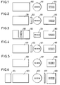
- the postal imprint shown in FIG. 1 includes a stamp 100 having a height of 24mm and a length of 20mm, an office block 101 with a diameter of 24mm, a mention "Slogan" 102 having a height of 25mm and a length of 50mm or a length of 70mm.
- the first shown in Figure 2 has a stamp 200 having a length of 35.5mm and a height of 22mm, a block desk 201 with a diameter of 22.4mm, a mention "First Class” 202 having a length of 5.23mm and a height of 19.05mm, a mention “Slogan” 203 having a height of 25mm and a length of 46, 7mm.
- stamp 300 having a length of 35.5mm and a height of 22mm
- office block 301 having a length of 19.81mm and a height of 14.48mm
- mention "Slogan” 302 having a height of 25mm and a length of 49.5mm
- number block 303 with 5 digits of 3mm height each.
- the postal imprint shown in Figure 4 includes a stamp 400 having a length of 35.5mm and a height of 22mm, an office block 401 with a diameter of 22.4mm, a "First Class” 402 having a length of 5mm and a height of 19.05mm and a mention “Slogan” 403 having a height of 25mm and a length of 46.7mm.
- the imprint shown in FIG. 5 comprises a stamp 500 having a length of 26mm and a height of 22mm, an office block 501 with a diameter of 23mm and a mention "Slogan" 502 having a height of 22, 25mm and a length of 46.7mm.
- the postal imprint shown in Figure 6 includes a stamp 600 having a length of 26mm and a height of 30mm, a mention "Gebuhr Beieret" 601 having a length of 3mm and a height of 28mm, an office block 602 d 'a diameter of 26mm, a mention "Slogan” 603 having a height of 26mm and a length of 46.7mm, a mention of mail 604.
- the object of the invention is to provide a device for quickly equipping a printing head with a franking machine in order to adapt it to the postal provisions in force in the various countries.
- the subject of the invention is a cassette with printing plates for a franking machine printing drum, comprising a support having a plate support face, longitudinal guide and support members extending perpendicularly to the plate support face and engaged in bosses of said support and several separate printing plates each mounted interchangeably on at least one longitudinal guide and support member.
- the cassette can thus incorporate several stereotypes of mentions such as "First Class”, “Slogan” and “Penta” commonly used for the printing of postal prints.
- the longitudinal guide and support member is a socket and the cassette comprises three sockets.
- the invention extends to a printing drum for a franking machine, comprising a printing cylinder having a base, an axis of rotation perpendicular to the base and a partially cylindrical printing area facing outwards from the cylinder, the cylinder having a housing defined in part by two first walls extending radially from the printing area and a second wall extending parallel to the base and spaced therefrom by the first walls, the housing opening towards the printing area and towards the base of the cylinder, three pins extending axially from the second wall in the direction of the base of the cylinder being provided to be inserted axially in the sockets of the stereotyped cassette.
- the operator composes the postal imprint by means of a set of plates which he incorporates into the cassette, then directly inserts the cassette equipped with the plates into the printing drum in a single operation.
- the invention further extends to a printing head for a franking machine comprising a housing inside which is rotatably mounted the printing drum, the housing having a face in which is cut a facing opening. screw of the base of the printing drum, this opening being designed so that the printing cassette can be inserted therein in an axial direction by presenting the support face of the cassette perpendicular to this axial direction.
- the cassette can thus be easily inserted and extracted into and from the printing drum from the outside of the franking machine head.
- Figure 1 shows a postal imprint according to the provisions in force in France.
- Figure 2 shows a first postal imprint according to the provisions in force in the United States.
- Figure 3 shows a second postal imprint according to the provisions in force in the United States.
- Figure 4 shows a postal imprint according to the provisions in force in Canada.
- Figure 5 shows a postal imprint according to the provisions in force in Great Britain.
- Figure 6 shows a postal imprint according to the provisions in force in Germany.
- Figure 7 is a perspective view of a franking machine head according to the invention.
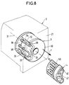
- Figure 8 is a perspective view of a plate cassette and a printing drum according to the invention.
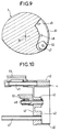
- Figure 9 is a cross-sectional view of the drum shown in Figure 8.
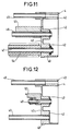
- Figures 10,11,12 show respectively a cassette with stereotypes in axial longitudinal section equipped in American / Canadian, German and French / English version.
- the head of a franking machine comprises a box 2 inside which is placed a printing drum 3.
- the drum is mounted rotating on an axis of rotation 31 passing through the rear face 21 of the housing.
- the printing drum comprises a printing cylinder having a base 30, an axis of rotation 31 perpendicular to the base and a partially cylindrical printing zone 32 turned towards the outside of the cylinder.
- An opening 20 is cut in the rear face 21 of the casing opposite the base 30 of the printing drum as visible in FIG. 7.
- This opening 20 is designed so as to be able to insert the plate cassette 4 in an axial direction indicated by the arrow f.
- the cassette 4 comprises a support 40 on which are mounted several plates each carrying a mention, only one 50 being shown.
- the cassette 4 is passed through the opening 20, the plate 50 in front.
- the plate 50 is inserted into the print drum and the support 40 is fitted into the opening 20 which forms a housing.
- the printing drum 3 comprises a housing 33 intended to receive stereotypes of the cassette 4.
- this housing is in the form of a quarter of a cylinder defined by two walls 34, 35 extending radially and by a wall partially circular 36 distant from the base 30 and separated from the latter by the walls 34, 35.
- three pins 37, 38, 39 protrude and extend in the direction of the base 30 parallel to the axis 31. These three pins are spaced from each other and placed at equal distance from the axis 31 on an internal generator of the cylinder.
- the support 40 of the cassette has a section complementary to that of the housing 33, here in the form of a bean.
- FIG. 9 two plates 51 and 52 are shown in section inside the drum 3. These two plates are held on the support 40 by three sockets 47,48,49, the pins 37 to 39 and the sockets 47 to 49 being arranged to fit into each other respectively.
- the sockets 47 to 49 extend perpendicular to the plate support surface 43 defining the front face of the support. These sockets are also held in the support 40, by means of bosses 42 which project from the side of the rear face of the support.
- the cavity formed between the bosses serves to receive a plug for the extraction of the cassette from the head of the franking machine.
- the plates are designed to be interchangeable and easily extracted from the sockets, for example using a suitable tool.
- a space 23 is also provided in the box 2 of the head for storing this tool and spare shots stored on a cover 22 closing the space 23 as visible in FIG. 7.
- a safety pull tab 24 is also slidably mounted on the rear face 21 of the housing to overlap the opening 20 when the cassette is inserted in the head so as to easily control the correct insertion of the support 40 in the opening 20.
- the cassette 4 is shown equipped in its United States / Canada version. It carries on its sleeve 49 a plate of mention "First Class” 51, on its sleeve 48 a control cam 52 of a plate of mention “Slogan”, and nothing on its sleeve 47.
- the cassette 4 is shown equipped in its Germany version. It has nothing on its socket 49, a photograph of "Slogan” 53 on its socket 48 and a photograph of "Penta” 54 on its socket 47.
- the cassette 4 is shown equipped in its France / Great Britain version. It has nothing on its socket 49, a control cam 52 with a "Slogan” plate on its socket 48 and nothing on its socket 47.
Landscapes
- Devices For Checking Fares Or Tickets At Control Points (AREA)
- Time Recorders, Dirve Recorders, Access Control (AREA)
- Printing Plates And Materials Therefor (AREA)
Description
- L'invention porte sur une tête de machine à affranchir électronique.
- Les machines à affranchir électroniques sont bien connues et largement utilisées dans la plupart des entreprises et bureaux de poste des pays industrialisés.
- Une tête de machine à affranchir électronique comporte un tambour d'impression fonctionnant d'une façon bien connue pour réaliser, par une simple révolution, une opération d'impression d'une empreinte postale sur le dos d'une enveloppe ou autre article de courrier à affranchir.
- Le brevet EP 0217576 décrit une tête de machine à affranchir comportant un tambour d'impression dans lequel est prévu un logement adapté pour recevoir un ensemble de roues d'impression pour imprimer 4 ou 5 chiffres de 0 à 9 d'un timbre, chaque roue étant montée tournante pour la sélection du chiffre à imprimer afin d'imprimer un montant voulu du timbre.
- Le tambour d'impression de cette tête comporte encore d'autres logements pour recevoir des clichés pourvus de mentions supplémentaires telles que les "First Class", "Slogan" et "Penta" à imprimer à côté du timbre sur le dos de l'enveloppe ou autre article de courrier.
- Différents pays ont différentes règles et habitudes en ce qui concerne l'impression de ces mentions supplémentaires.
- Ainsi en France, l'empreinte postale montrée sur la figure 1 comporte un timbre 100 ayant une hauteur de 24mm et une longueur de 20mm, un bloc bureau 101 d'un diamètre de 24mm, une mention "Slogan" 102 ayant une hauteur de 25mm et une longueur de 50mm ou une longueur de 70mm.
- Aux Etats Unis, il existe deux empreintes postales. La première montrée sur la figure 2 comporte un timbre 200 ayant une longueur de 35,5mm et une hauteur de 22mm, un bloc bureau 201 d'un diamètre de 22,4mm, une mention "First Class" 202 ayant une longueur de 5,23mm et une hauteur de 19,05mm, une mention "Slogan" 203 ayant une hauteur de 25mm et une longueur de 46,7mm. La seconde montrée sur la figure 3 comporte un timbre 300 ayant une longueur de 35,5mm et une hauteur de 22mm, un bloc bureau 301 ayant une longueur de 19,81mm et une hauteur de 14,48mm, une mention "Slogan" 302 ayant une hauteur de 25mm et une longueur de 49,5mm et un bloc numéroteur 303 à 5 chiffres de 3mm de hauteur chacun.
- Au Canada, l'empreinte postale montrée sur la figure 4 comporte un timbre 400 ayant une longueur de 35,5mm et une hauteur de 22mm, un bloc bureau 401 d'un diamètre de 22,4mm, une mention "First Class" 402 ayant une longueur de 5mm et une hauteur de 19,05mm et une mention "Slogan" 403 ayant une hauteur de 25mm et une longueur de 46,7mm.
- En Grande Bretagne, l'empreinte montrée sur la figure 5 comporte un timbre 500 ayant une longueur de 26mm et une hauteur de 22mm, un bloc bureau 501 d'un diamètre de 23mm et une mention "Slogan" 502 ayant une hauteur de 22,25mm et une longueur de 46,7mm.
- En Allemagne, l'empreinte postale montrée sur la figure 6 comporte un timbre 600 ayant une longueur de 26mm et une hauteur de 30mm, une mention "Gebuhr Bezahlt" 601 ayant une longueur de 3mm et une hauteur de 28mm, un bloc bureau 602 d'un diamètre de 26mm, une mention "Slogan" 603 ayant une hauteur de 26mm et une longueur de 46,7mm, une mention de courrier 604.
- Dans le tambour d'impression connu du document cité précédemment, il est prévu d'insérer des clichés séparés à l'intérieur de logements respectifs disposés sur la périphérie du tambour en fonction des différentes dispositions postales en vigueur dans les différents pays pour l'impression des mentions supplémentaires adéquates. Ces différents logements compliquent la structure du tambour d'impression ainsi que l'opération de configuration de la tête d'impression puisqu'il faut autant de logements séparés qu'il y a de mentions supplémentaires à imprimer dans l'empreinte postale considérée.
- Le but de l'invention est de proposer un dispositif permettant d'équiper rapidement une tête d'impression de machine à affranchir en vue de l'adapter aux dispositions postales en vigueur dans les différents pays.
- A cet effet, l'invention a pour objet une cassette à clichés d'impression pour tambour d'impression de machine à affranchir, comprenant un support ayant une face support de clichés, des organes longitudinaux de guidage et de support s'étendant perpendiculairement à la face support de clichés et en prise dans des bossages dudit support et plusieurs clichés d'impression séparés monté chacun de façon interchangeable sur au moins un organe longitudinal de guidage et de support.
- La cassette peut ainsi incorporer plusieurs clichés de mentions telles que "First Class", "Slogan" et "Penta" couramment utilisées pour l'impression d'empreintes postales.
- Selon un mode de réalisation simple, l'organe longitudinal de guidage et de support est une douille et la cassette comporte trois douilles.
- L'invention s'étend à un tambour d'impression pour une machine à affranchir, comprenant un cylindre d'impression ayant une base, un axe de rotation perpendiculaire à la base et une zone d'impression partiellement cylindrique tournée vers l'extérieur du cylindre, le cylindre présentant un logement délimité en partie par deux premières parois s'étendant radialement depuis la zone d'impression et une seconde paroi s'étendant parallèlement à la base et espacée de celle-ci par les premières parois, le logement débouchant vers la zone d'impression et vers la base du cylindre, trois broches s'étendant axialement depuis la seconde paroi en direction de la base du cylindre étant prévues pour s'insérer axialement dans les douilles de la cassette à clichés.
- Dès lors, l'opérateur compose l'empreinte postale au moyen d'un jeu de clichés qu'il incorpore dans la cassette, puis insère directement la cassette équipée des clichés dans le tambour d'impression en une seule manoeuvre.
- L'invention s'étend encore à une tête d'impression pour machine à affranchir comprenant un boîtier à l'intérieur duquel est monté tournant le tambour d'impression, le boîtier ayant une face dans laquelle est découpée une ouverture en vis-à-vis de la base du tambour d'impression, cette ouverture étant conçue de manière que la cassette à clichés puisse y être insérée selon une direction axiale en présentant la face support de la cassette perpendiculairement à cette direction axiale.
- La cassette peut ainsi être insérée et extraite facilement dans et du tambour d'impression depuis l'extérieur de la tête de machine à affranchir.
- L'invention est maintenant décrite en détail ci-dessous en référence aux dessins.
- La figure 1 montre une empreinte postale selon les dispositions en vigueur en France.
- La figure 2 montre une première empreinte postale selon les dispositions en vigueur aux Etats Unis.
- La figure 3 montre une seconde empreinte postale selon les dispositions en vigueur aux Etats Unis.
- La figure 4 montre une empreinte postale selon les dispositions en vigueur au Canada.
- La figure 5 montre une empreinte postale selon les dispositions en vigueur en Grande Bretagne.
- La figure 6 montre une empreinte postale selon les dispositions en vigueur en Allemagne.
- La figure 7 est une vue en perspective d'une tête de machine à affranchir selon l'invention.
- La figure 8 est une vue en perspective d'une cassette à clichés et d'un tambour d'impression selon l'invention.
- La Figure 9 est une vue en coupe transversale du tambour montré à la figure 8.
- Les figures 10,11,12 montrent respectivement une cassette à clichés en coupe longitudinale axiale équipée en version américaine/canadienne, allemande et française/anglaise.
- Sur les figures 7 et 8, la tête d'une machine à affranchir comporte un boîtier 2 à l'intérieur duquel est placé un tambour d'impression 3. Le tambour est monté tournant sur un axe de rotation 31 traversant la face arrière 21 du boitier.
- Sur la figure 8, le tambour d'impression comprend un cylindre d'impression ayant une base 30, un axe de rotation 31 perpendiculaire à la base et une zone d'impression 32 partiellement cylindrique tournée vers l'extérieur du cylindre.
- Une ouverture 20 est découpée dans la face arrière 21 du boîtier en vis-à-vis de la base 30 du tambour d'impression comme visible sur la figure 7.
- Cette ouverture 20 est conçue de manière à pouvoir insérer la cassette à clichés 4 selon une direction axiale indiquée par la flèche f.
- Sur les figures 7 et 8, la cassette 4 comprend un support 40 sur lequel sont montés plusieurs clichés portant chacun une mention, un seul 50 étant montré.
- Comme montré sur ces figures, la cassette 4 est passée au travers de l'ouverture 20, le cliché 50 en avant. Lorsque la cassette 4 est complètement insérée dans la tête d'impression, le cliché 50, est inséré dans le tambour d'impression et le support 40 vient s'encastrer dans l'ouverture 20 qui forme un logement.
- Sur la figure 8, le tambour d'impression 3 comporte un logement 33 prévu pour recevoir des clichés de la cassette 4. ce logement est en forme de quartier de cylindre défini par deux parois 34,35 s'étendant radialement et par une paroi partiellement circulaire 36 distante de la base 30 et séparée de celle-ci par les parois 34,35.
- Sur la paroi 36, trois broches 37,38,39 font saillie et s'étendent en direction de la base 30 parallèlement à l'axe 31. Ces trois broches sont distantes l'une de l'autre et placées à égale distance de l'axe 31 sur une génératrice interne du cylindre.
- Le support 40 de la cassette a une section complémentaire à celle du logement 33, ici en forme de haricot.
- Sur la figure 9, deux clichés 51 et 52 sont montrés en section à l'intérieur du tambour 3. Ces deux clichés sont maintenus sur le support 40 par trois douilles 47,48,49, les broches 37 à 39 et les douilles 47 à 49 étant agencées pour s'insérer respectivement l'une dans l'autre.
- Sur les figures 10 à 12, les douilles 47 à 49 s'étendent perpendiculairement à la surface support de clichés 43 définissant la face avant du support. Ces douilles sont par ailleurs tenues dans le support 40, par l'intermédiaire de bossages 42 qui font saillie du côté de la face arrière du support.
- La cavité constituée entre les bossages sert à recevoir un bouchon pour l'extraction de la cassette de la tête de la machine à affranchir.
- Les clichés sont prévus pour être interchangeables et extraits facilement des douilles, par exemple à l'aide d'un outil adapté. Un espace 23 est d'ailleurs prévu dans le boîtier 2 de la tête pour ranger cet outil et des clichés de rechange rangés sur un couvercle 22 venant fermer l'espace 23 comme visible sur la figure 7.
- Une tirette de sécurité 24 est aussi montée coulissante sur la face arrière 21 du boîtier pour venir chevaucher l'ouverture 20 lorsque la cassette est insérée dans la tête de façon à contrôler facilement l'insertion correcte du support 40 dans l'ouverture 20. Pour insérer la cassette 4 dans l'ouverture 20, il est nécessaire de présenter la face 43 du support 40 perpendiculaire à l'axe 31.
- Sur la figure 10, la cassette 4 est montrée équipée dans sa version Etats-Unis/Canada. Elle porte sur sa douille 49 un cliché de mention "First Class" 51, sur sa douille 48 une came de commande 52 d'un cliché de mention "Slogan", et rien sur sa douille 47.
- Sur la figure 11, la cassette 4 est montrée équipée dans sa version Allemagne. Elle porte rien sur sa douille 49, un cliché de mention "Slogan" 53 sur sa douille 48 et un cliché de mention "Penta" 54 sur sa douille 47.
- Sur la figure 12, la cassette 4 est montrée équipée dans sa version France/Grande Bretagne. Elle ne porte rien sur sa douille 49, une came de commande 52 de cliché "Slogan" sur sa douille 48 et rien sur sa douille 47.
Claims (5)
- Une cassette (4) à clichés d'impression pour tambour d'impression (3) de machine à affranchir, comprenant un support (40) ayant une face (43) support de clichés, des organes longitudinaux (47,48,49) de guidage et de support s'étendant perpendiculairement à la face support de clichés et en prise dans des bossages (42) dudit support et plusieurs clichés d'impression séparés (50,51,52,53,54) monté chacun de façon interchangeable sur au moins un organe longitudinal de guidage et de support.
- La cassette selon la revendication 1, dans laquelle l'organe longitudinal de guidage et de support est une douille.
- La cassette selon la revendication 2, comportant trois douilles (47,48,49).
- Un tambour d'impression (3) pour une machine à affranchir, comprenant un cylindre d'impression ayant une base (30), un axe de rotation (31) perpendiculaire à la base et une zone d'impression (32) partiellement cylindrique tournée vers l'extérieur du cylindre, le cylindre présentant un logement (33) délimité en partie par deux premières parois (34,35) s'étendant radialement depuis la zone d'impression et une seconde paroi (36) s'étendant parallèlement à la base et espacée de celle-ci par les premières parois, le logement débouchant vers la zone d'impression et vers la base du cylindre, trois broches (37,38,39) s'étendant axialement depuis la seconde paroi en direction de la base du cylindre étant prévues pour s'insérer axialement dans les douilles de la cassette à clichés selon la revendication 3.
- Une tête d'impression pour machine à affranchir comprenant un boîtier (2) à l'intérieur duquel est monté tournant le tambour d'impression (3) selon la revendication 4, le boîtier ayant une face (21) dans laquelle est découpée une ouverture (20) en vis-à-vis de la base du tambour d'impression, cette ouverture étant conçue de manière que la cassette à clichés selon la revendication 3 puisse y être insérée selon une direction axiale en présentant la face support de la cassette perpendiculairement à cette direction axiale.
Applications Claiming Priority (2)
| Application Number | Priority Date | Filing Date | Title |
|---|---|---|---|
| FR9310473A FR2709443B1 (fr) | 1993-09-02 | 1993-09-02 | Cassette à clichés d'impression pour tambour d'impression de machines à affranchir. |
| FR9310473 | 1993-09-02 |
Publications (2)
| Publication Number | Publication Date |
|---|---|
| EP0641668A1 EP0641668A1 (fr) | 1995-03-08 |
| EP0641668B1 true EP0641668B1 (fr) | 1997-06-18 |
Family
ID=9450515
Family Applications (1)
| Application Number | Title | Priority Date | Filing Date |
|---|---|---|---|
| EP94401920A Expired - Lifetime EP0641668B1 (fr) | 1993-09-02 | 1994-08-30 | Cassette à cliches d'impression pour tambour d'impression de machine à affranchir |
Country Status (4)
| Country | Link |
|---|---|
| US (1) | US5495802A (fr) |
| EP (1) | EP0641668B1 (fr) |
| DE (1) | DE69403870T2 (fr) |
| FR (1) | FR2709443B1 (fr) |
Families Citing this family (1)
| Publication number | Priority date | Publication date | Assignee | Title |
|---|---|---|---|---|
| US20080154425A1 (en) * | 2006-04-27 | 2008-06-26 | Velociti Alliance North America, Inc. | Systems and methods for stamping packaged goods in the nature of cigarettes |
Family Cites Families (5)
| Publication number | Priority date | Publication date | Assignee | Title |
|---|---|---|---|---|
| US1633245A (en) * | 1925-03-09 | 1927-06-21 | Red Star Appliances Inc | Stamp-canceling machine |
| FR1031342A (fr) * | 1951-01-24 | 1953-06-23 | Outil R B V L | Perfectionnements aux rouleaux porte-timbre |
| US3064566A (en) * | 1959-08-03 | 1962-11-20 | Lynch Corp | Code dater |
| US4252061A (en) * | 1979-09-17 | 1981-02-24 | Wade Jr Charles E | Dating wheels |
| GB2180193B (en) * | 1985-09-16 | 1989-12-20 | Pitney Bowes Plc | A postage meter having a print drum. |
-
1993
- 1993-09-02 FR FR9310473A patent/FR2709443B1/fr not_active Expired - Fee Related
-
1994
- 1994-08-30 DE DE69403870T patent/DE69403870T2/de not_active Expired - Fee Related
- 1994-08-30 EP EP94401920A patent/EP0641668B1/fr not_active Expired - Lifetime
- 1994-09-01 US US08/299,545 patent/US5495802A/en not_active Expired - Fee Related
Also Published As
| Publication number | Publication date |
|---|---|
| FR2709443A1 (fr) | 1995-03-10 |
| FR2709443B1 (fr) | 1995-12-01 |
| EP0641668A1 (fr) | 1995-03-08 |
| DE69403870D1 (de) | 1997-07-24 |
| US5495802A (en) | 1996-03-05 |
| DE69403870T2 (de) | 1997-10-09 |
Similar Documents
| Publication | Publication Date | Title |
|---|---|---|
| FR2618730A1 (fr) | Imprimante d'etiquettes | |
| MC1039A1 (fr) | Distributeur de pièces de monnaie | |
| EP0217576A2 (fr) | Cylindre d'impression pour machine à affranchir | |
| EP0117991A1 (fr) | Outil de coupe à couteaux amovibles | |
| EP0641668A1 (fr) | Cassette à cliches d'impression pour tambour d'impression de machine à affranchir | |
| EP0133328B1 (fr) | Machine d'impression rotative multicolore pour l'impression recto-verso simultanée | |
| CH669759A5 (fr) | ||
| EP0916489A1 (fr) | Dispositif pour le positionnement et la fixation d'outils sur une plaque de support et de chauffage | |
| FR2463682A1 (fr) | Tete d'impression a bandes mobiles et son procede de fabrication | |
| EP1183153A1 (fr) | Cylindre d'impression comprenant des moyens d'indexage pour le montage d'un manchon d'impression sur le cylindre support | |
| EP1510480B1 (fr) | Dispositif anti-biais pour machine de traitement de courrier | |
| FR2695872A1 (fr) | Dispositif de retournement, de format réglable, avec roues de changement, monté sur une machine rotative à imprimer des feuilles. | |
| FR2731892A1 (fr) | Dispositif pour le maintien de cintres dans un bagage et bagage equipe d'un tel dispositif | |
| US4437405A (en) | Apparatus for transferring ink to the ink plate of a metering machine | |
| CH658424A5 (en) | Cutting tool with removable cutters | |
| JPH0450117Y2 (fr) | ||
| EP0470550A1 (fr) | Dispositif de verrouillage de molettes d'une machine à affranchir | |
| WO2009068813A2 (fr) | Mecanisme d'impression thermique d'une bande a imprimer comprenant deux vis helicoidales pour l'entrainement en rotation d'un arbre d'entree d'un rouleau d'impression | |
| BE901555A (fr) | Machine rotative d'impression combinee. | |
| EP0633134B1 (fr) | Machine d'impression taille-douce | |
| CH346564A (fr) | Cylindre d'impression | |
| BE624659A (fr) | ||
| CH268178A (de) | Machine à imprimer. | |
| BE897084R (fr) | Dispositif pour le controle du temps de stationnement payant des vehicules automobiles | |
| FR2617073A3 (fr) | Dispositif adaptateur pour machines duplicatrices de cles |
Legal Events
| Date | Code | Title | Description |
|---|---|---|---|
| PUAI | Public reference made under article 153(3) epc to a published international application that has entered the european phase |
Free format text: ORIGINAL CODE: 0009012 |
|
| AK | Designated contracting states |
Kind code of ref document: A1 Designated state(s): DE FR GB NL |
|
| 17P | Request for examination filed |
Effective date: 19950830 |
|
| GRAG | Despatch of communication of intention to grant |
Free format text: ORIGINAL CODE: EPIDOS AGRA |
|
| 17Q | First examination report despatched |
Effective date: 19960812 |
|
| GRAH | Despatch of communication of intention to grant a patent |
Free format text: ORIGINAL CODE: EPIDOS IGRA |
|
| GRAH | Despatch of communication of intention to grant a patent |
Free format text: ORIGINAL CODE: EPIDOS IGRA |
|
| GRAA | (expected) grant |
Free format text: ORIGINAL CODE: 0009210 |
|
| AK | Designated contracting states |
Kind code of ref document: B1 Designated state(s): DE FR GB NL |
|
| PG25 | Lapsed in a contracting state [announced via postgrant information from national office to epo] |
Ref country code: NL Free format text: LAPSE BECAUSE OF FAILURE TO SUBMIT A TRANSLATION OF THE DESCRIPTION OR TO PAY THE FEE WITHIN THE PRESCRIBED TIME-LIMIT Effective date: 19970618 |
|
| REF | Corresponds to: |
Ref document number: 69403870 Country of ref document: DE Date of ref document: 19970724 |
|
| GBT | Gb: translation of ep patent filed (gb section 77(6)(a)/1977) |
Effective date: 19970815 |
|
| NLV1 | Nl: lapsed or annulled due to failure to fulfill the requirements of art. 29p and 29m of the patents act | ||
| PLBE | No opposition filed within time limit |
Free format text: ORIGINAL CODE: 0009261 |
|
| STAA | Information on the status of an ep patent application or granted ep patent |
Free format text: STATUS: NO OPPOSITION FILED WITHIN TIME LIMIT |
|
| 26N | No opposition filed | ||
| PGFP | Annual fee paid to national office [announced via postgrant information from national office to epo] |
Ref country code: FR Payment date: 19990709 Year of fee payment: 6 |
|
| PGFP | Annual fee paid to national office [announced via postgrant information from national office to epo] |
Ref country code: DE Payment date: 19990726 Year of fee payment: 6 |
|
| PGFP | Annual fee paid to national office [announced via postgrant information from national office to epo] |
Ref country code: GB Payment date: 19990819 Year of fee payment: 6 |
|
| PG25 | Lapsed in a contracting state [announced via postgrant information from national office to epo] |
Ref country code: GB Free format text: LAPSE BECAUSE OF NON-PAYMENT OF DUE FEES Effective date: 20000830 |
|
| GBPC | Gb: european patent ceased through non-payment of renewal fee |
Effective date: 20000830 |
|
| PG25 | Lapsed in a contracting state [announced via postgrant information from national office to epo] |
Ref country code: FR Free format text: LAPSE BECAUSE OF NON-PAYMENT OF DUE FEES Effective date: 20010430 |
|
| PG25 | Lapsed in a contracting state [announced via postgrant information from national office to epo] |
Ref country code: DE Free format text: LAPSE BECAUSE OF NON-PAYMENT OF DUE FEES Effective date: 20010501 |
|
| REG | Reference to a national code |
Ref country code: FR Ref legal event code: ST |