EP0641963A1 - Vanne mitigeuse à levier unique - Google Patents
Vanne mitigeuse à levier unique Download PDFInfo
- Publication number
- EP0641963A1 EP0641963A1 EP94110934A EP94110934A EP0641963A1 EP 0641963 A1 EP0641963 A1 EP 0641963A1 EP 94110934 A EP94110934 A EP 94110934A EP 94110934 A EP94110934 A EP 94110934A EP 0641963 A1 EP0641963 A1 EP 0641963A1
- Authority
- EP
- European Patent Office
- Prior art keywords
- cross
- head piece
- disk
- regulating
- disc
- Prior art date
- Legal status (The legal status is an assumption and is not a legal conclusion. Google has not performed a legal analysis and makes no representation as to the accuracy of the status listed.)
- Granted
Links
- 230000001105 regulatory effect Effects 0.000 claims abstract description 31
- XLYOFNOQVPJJNP-UHFFFAOYSA-N water Substances O XLYOFNOQVPJJNP-UHFFFAOYSA-N 0.000 claims abstract description 14
- 238000006073 displacement reaction Methods 0.000 claims abstract description 6
- 229920003023 plastic Polymers 0.000 claims description 4
- 239000004033 plastic Substances 0.000 claims description 4
- 230000008878 coupling Effects 0.000 claims description 3
- 238000010168 coupling process Methods 0.000 claims description 3
- 238000005859 coupling reaction Methods 0.000 claims description 3
- 238000002347 injection Methods 0.000 claims description 2
- 239000007924 injection Substances 0.000 claims description 2
- 230000000295 complement effect Effects 0.000 abstract 1
- 238000004519 manufacturing process Methods 0.000 description 5
- 230000005540 biological transmission Effects 0.000 description 3
- 230000000977 initiatory effect Effects 0.000 description 2
- 239000004952 Polyamide Substances 0.000 description 1
- 229920000122 acrylonitrile butadiene styrene Polymers 0.000 description 1
- 239000000919 ceramic Substances 0.000 description 1
- 230000001276 controlling effect Effects 0.000 description 1
- 230000001419 dependent effect Effects 0.000 description 1
- 230000001627 detrimental effect Effects 0.000 description 1
- 230000000694 effects Effects 0.000 description 1
- 238000001746 injection moulding Methods 0.000 description 1
- 229920002647 polyamide Polymers 0.000 description 1
- 238000004904 shortening Methods 0.000 description 1
- 239000000243 solution Substances 0.000 description 1
Images


Classifications
-
- F—MECHANICAL ENGINEERING; LIGHTING; HEATING; WEAPONS; BLASTING
- F16—ENGINEERING ELEMENTS AND UNITS; GENERAL MEASURES FOR PRODUCING AND MAINTAINING EFFECTIVE FUNCTIONING OF MACHINES OR INSTALLATIONS; THERMAL INSULATION IN GENERAL
- F16K—VALVES; TAPS; COCKS; ACTUATING-FLOATS; DEVICES FOR VENTING OR AERATING
- F16K11/00—Multiple-way valves, e.g. mixing valves; Pipe fittings incorporating such valves
- F16K11/02—Multiple-way valves, e.g. mixing valves; Pipe fittings incorporating such valves with all movable sealing faces moving as one unit
- F16K11/06—Multiple-way valves, e.g. mixing valves; Pipe fittings incorporating such valves with all movable sealing faces moving as one unit comprising only sliding valves, i.e. sliding closure elements
- F16K11/078—Multiple-way valves, e.g. mixing valves; Pipe fittings incorporating such valves with all movable sealing faces moving as one unit comprising only sliding valves, i.e. sliding closure elements with pivoted and linearly movable closure members
- F16K11/0782—Single-lever operated mixing valves with closure members having flat sealing faces
- F16K11/0787—Single-lever operated mixing valves with closure members having flat sealing faces with both the supply and the discharge passages being on the same side of the closure members
-
- F—MECHANICAL ENGINEERING; LIGHTING; HEATING; WEAPONS; BLASTING
- F16—ENGINEERING ELEMENTS AND UNITS; GENERAL MEASURES FOR PRODUCING AND MAINTAINING EFFECTIVE FUNCTIONING OF MACHINES OR INSTALLATIONS; THERMAL INSULATION IN GENERAL
- F16K—VALVES; TAPS; COCKS; ACTUATING-FLOATS; DEVICES FOR VENTING OR AERATING
- F16K31/00—Actuating devices; Operating means; Releasing devices
- F16K31/44—Mechanical actuating means
- F16K31/60—Handles
- F16K31/605—Handles for single handle mixing valves
Definitions
- the invention relates to a single-lever mixer valve according to the preamble of the main claim.
- Such a single-lever mixer valve is known from DE 36 00 959 C2, from which the invention is based.
- the guide part seated on the regulating disk (called a cover disk there) has a radially extending rib or raised portion in the center, which is delimited by two recesses.
- the head piece of the actuating shaft is designed in a fork-shaped manner such that two arms and a depression are formed between them, the two arms interacting positively with the recesses in the guide part and the rib or raised portion of the guide part with the recess in the actuating lever.
- the head piece engages in a claw-like manner on the rib attached above the guide part.
- the regulating wheel can be moved translationally when the control shaft is moved about its pivot axis, it is necessary to design the rib on the guide part as well as the recess between the fork-shaped ends of the control shaft head, because this requires the relative displacement of the two parts to occur.
- the overall arrangement is heavily dependent on manufacturing tolerances. A slight displacement of the wedge-shaped recess between the fork-shaped ends of the actuating shaft towards its pivot axis requires a more or less large game between the interlocking ones Share. However, such a game is extremely detrimental to the desired operating comfort, which is to be characterized in particular by a rich handling.
- the known arrangement has yet another disadvantage, which consists in the fact that the fork-shaped ends on the head piece of the actuating shaft have to transmit both the translational movements and, at the same time, the rotary movements on the guide part and thus on the regulating wheel due to their attack on the rib of the guide part .
- the fork-shaped ends on the head piece of the actuating shaft have to transmit both the translational movements and, at the same time, the rotary movements on the guide part and thus on the regulating wheel due to their attack on the rib of the guide part .
- the present invention is therefore essentially based on the object of creating a single-lever mixer valve of the type assumed at the outset, in which the forces, in particular the forces serving the rotary movement of the regulating disk, optimally, i.e. Above all, wear-resistant, let it start and, with the manufacturing and assembly tolerances, have no or at least no appreciable negative influence on the ease of operation of the valve.
- the invention solves this problem primarily and essentially with the features specified in the characterizing part of the main claim.
- the head piece of the actuating shaft engages in a form-fit manner in a cross configuration with a complementarily designed cross groove on the back of the regulating disk (generally on the back of the guide part).
- a first, central cross section serves to introduce and transmit those forces which translate the regulating wheel.
- This first cross section is designed essentially in the form of a pin and can lie in the associated groove section without manufacturing tolerances in the direction of the pivot bearing of the actuating shaft playing a role with regard to the accuracy of fit.
- those forces which serve their rotary movement are also transferred from the head part of the control shaft to the regulating wheel.
- the cross sections extending perpendicular to the cross section mentioned are provided, in which the head piece is immersed with a swivel-sliding sword. Its side flanks can be supported essentially flat on the groove walls for transmitting the forces initiating the rotary movement, and at a relatively large distance from the cross center, as a result of which the greatest possible lever arms are effective.
- the invention cleverly uses the flanks of the grooves incorporated in the guide part or the regulating disk or the groove sections for torque transmission.
- the solution according to the invention is particularly suitable for being able to manufacture the control shaft including its head piece from a one-piece plastic injection molding, which is due to the previously high level Wear of such arrangements was not possible or only possible under considerable circumstances.
- the cross groove and the cross section can be designed or arranged in a single cross shape, approximately in the shape of an X, or in a double cross shape, for example in the shape of an H.
- a single-lever mixer valve is designated by 10 in total.
- the assembly shown in FIGS. 1 to 3 is usually referred to as a 'cartridge'.
- the mixing valve comprises a cartridge housing 11 with two inlet openings for hot and cold water 12 (only one is shown in FIGS. 1 and 2) and a water outlet opening 13.
- these passage openings 12, 13 are incorporated in a special base plate 14 inserted into the lower mouth of the cartridge housing 11.
- a first control disc In the interior of the cartridge housing 11 and immediately above the base plate 14 is a first control disc, the fixed disc 15, fixed in space, i.e. neither slidable nor rotatable, attached. It also has two water inlet openings 16 and a water outlet opening 17, the through openings 16 communicating with the through openings 12 of the base plate and the openings 17 communicating with the openings 13 of the base plate 14.
- a second control disk sits directly on the surface of the fixed disk 15 and is designated 18.
- it is arranged both rotatably and translationally displaceable relative to the fixed disk 15. It has a water passage opening 19, which by rotating and shifting its position relative to the passage openings 16, 17 of the fixed disk 15, the amount of water and the mixing ratio of cold water / hot water can be set by different overlap to the passage openings 16 and 17 in the fixed disk.
- Both the fixed disk 15 and the regulating disk 18 are usually made of ceramic.
- the regulating disk 18 is overlapped by a hood-like guide part 36, which is made in particular of plastic, the regulating disk 18 and the guide part 36 being connected to one another in a form-fitting manner and thus in a uniform movement.
- the guide part 36 adjoins a neck part 20, which is axially fixed within a sleeve-shaped section 21 of the cartridge housing 11, but is rotatably guided about the vertical central axis 22.
- the neck part 20 supports, on an axis 23, an actuating shaft designated by 24 in the direction 25 (FIG. 1) or the opposite direction 26 (FIG. 2).
- the pivotable arrangement of the control shaft 24 serves to adjust the amount of water emerging from the fitting and causes the translational displacement of the regulating disk 18 between the flow-blocking one extreme position according to FIG. 1 and the extreme position shown in FIG. 2 for the maximum open passage.
- the temperature is set by rotating the regulating disk 18 above the fixed disk 15 by pivoting the setting shaft about the vertical axis 22.
- control shaft 24 has a specially designed head piece 27 at its lower end below its pivot axis 18.
- the entire control shaft 24, including its head piece 27, preferably consists of a one-piece injection molded body made of plastic, such as polyamide or ABS plastic.
- the head piece 27 at the lower free end of the actuating shaft 24 has two short peg-shaped stub axles 28 with an essentially cylindrical surface 29 for controlling the regulating disk 18.
- the longitudinal central axis 30 of the journal 28 extends in the same longitudinal central plane 31 of the actuating shaft 24 as the pivot axis 23 and parallel to its geometrical longitudinal axis 32.
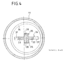
- wing-like sections extend essentially on both sides towards the head 27, in cross section rectangular swords 33.
- the two centrally located stub axles 28 form a cross with the two wings representing a sword 33.
- Each of the four sections or branches of this cross is assigned to a branch of a cross groove 34 which is arranged on the top of the guide part 36.
- a short groove section 35 an axle journal 28 of the head piece 27 of the actuating shaft 24 is pivotally mounted and in this way transmits in the direction when the actuating shaft 24 is pivoted about the axis 23 25 and 26, respectively, the forces for translational displacement of the guide part 36 and consequently the regulating disk 18 connected to it.
- the sword 33 can also be guided in the groove sections serving to receive it, with a slight clamping engagement.
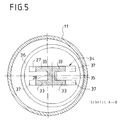
- FIG. 5 is also a cross-shaped configuration of the engagement area in the sense of the invention shown between the head part 27 of the actuating shaft 24 and the guide part 36, but now essentially in an H-shape, which could consequently also be referred to as a double-T profile.
- two swords or four wings of the sword 33 are now formed on the head piece 27, which, as can be seen in FIG. 5, are integrally formed on the outside of a central pivot pin. This arrangement naturally allows an even higher torque transmission with otherwise unchanged advantages compared to the embodiment according to FIG. 4.
- the respective opposite walls of the groove 24 are essentially plane-parallel, which means that the overall arrangement is free from influences which may result from dimensional tolerances in the manufacture or assembly of the control shaft 24. With regard to the low-clearance or even clearance-free engagement of the head piece 27 in the groove arrangement 34, it is therefore irrelevant how deep this engagement takes place. Depending on the resulting tolerances, only the transverse adjustment path for the guide part 36 and the regulating disk carried by it is 18, but this has no influence on the operating comfort of the valve.
Landscapes
- Engineering & Computer Science (AREA)
- General Engineering & Computer Science (AREA)
- Mechanical Engineering (AREA)
- Multiple-Way Valves (AREA)
- Mechanically-Actuated Valves (AREA)
- Mixers Of The Rotary Stirring Type (AREA)
Applications Claiming Priority (3)
| Application Number | Priority Date | Filing Date | Title |
|---|---|---|---|
| DE4329747A DE4329747A1 (de) | 1993-09-03 | 1993-09-03 | Einhebelmischventil |
| DE4329747 | 1993-09-03 | ||
| DE9313271U DE9313271U1 (de) | 1993-09-03 | 1993-09-03 | Einhebelmischventil |
Publications (2)
| Publication Number | Publication Date |
|---|---|
| EP0641963A1 true EP0641963A1 (fr) | 1995-03-08 |
| EP0641963B1 EP0641963B1 (fr) | 1996-12-11 |
Family
ID=25929190
Family Applications (1)
| Application Number | Title | Priority Date | Filing Date |
|---|---|---|---|
| EP94110934A Expired - Lifetime EP0641963B1 (fr) | 1993-09-03 | 1994-07-14 | Vanne mitigeuse à levier unique |
Country Status (5)
| Country | Link |
|---|---|
| EP (1) | EP0641963B1 (fr) |
| AT (1) | ATE146264T1 (fr) |
| DE (3) | DE9313271U1 (fr) |
| DK (1) | DK0641963T3 (fr) |
| ES (1) | ES2097580T3 (fr) |
Cited By (4)
| Publication number | Priority date | Publication date | Assignee | Title |
|---|---|---|---|---|
| EP0797034A1 (fr) * | 1996-03-19 | 1997-09-24 | Friedrich Grohe Aktiengesellschaft | Agencement de cartouche de robinet |
| KR100659987B1 (ko) * | 1998-06-08 | 2006-12-22 | 가부시키가이샤 후지킨 | 유체 제어기 |
| WO2009092688A1 (fr) * | 2008-01-21 | 2009-07-30 | Ceramtec Ag | Boîtier de cartouche |
| EP3608567A1 (fr) * | 2018-08-10 | 2020-02-12 | Oras Oy | Obturateur à disque pour robinet d'eau, robinet d'eau et procédé pour compenser les tolérances de fabrication dans un obturateur à disque |
Families Citing this family (5)
| Publication number | Priority date | Publication date | Assignee | Title |
|---|---|---|---|---|
| DE19580519B3 (de) * | 1994-03-31 | 2014-03-06 | Ntn Corp. | Ventilanordnung |
| US5417242A (en) * | 1994-04-14 | 1995-05-23 | Kohler Co. | Fluid valve |
| DE19741407A1 (de) * | 1997-09-19 | 1999-03-25 | Grohe Kg Hans | Ventilsystem, insbesondere für ein Einhebelmischventil |
| CN105090564A (zh) * | 2015-09-05 | 2015-11-25 | 凌石林 | 两进两出控制水阀及淋浴系统 |
| US11326715B2 (en) * | 2020-02-14 | 2022-05-10 | Delta Faucet Company | Snap-on faucet handle |
Citations (3)
| Publication number | Priority date | Publication date | Assignee | Title |
|---|---|---|---|---|
| EP0096005A1 (fr) * | 1982-05-28 | 1983-12-07 | Simeg-Brevet AG | Valve mitigeuse par un seul levier pour le réglage du débit et du rapport d'eau chaude et froide |
| DE3510351A1 (de) * | 1984-12-21 | 1986-07-03 | SOL S.p.A., Lumezzane, Brescia | Betaetigungsvorrichtung fuer einen mischhahn zum vermischen von warmwasser und kaltwasser |
| DE3600959A1 (de) * | 1985-09-19 | 1987-03-19 | Galatron Srl | Zum vermischen von warmwasser und kaltwasser dienendes mischventil |
Family Cites Families (2)
| Publication number | Priority date | Publication date | Assignee | Title |
|---|---|---|---|---|
| DE3503583A1 (de) * | 1984-07-03 | 1986-08-07 | Friedrich Grohe Armaturenfabrik Gmbh & Co, 5870 Hemer | Wassermischventil |
| DE3531936C2 (de) * | 1985-09-07 | 1994-08-11 | Rokal Armaturen Gmbh | Steuerkartusche |
-
1993
- 1993-09-03 DE DE9313271U patent/DE9313271U1/de not_active Expired - Lifetime
- 1993-09-03 DE DE4329747A patent/DE4329747A1/de not_active Ceased
-
1994
- 1994-07-14 ES ES94110934T patent/ES2097580T3/es not_active Expired - Lifetime
- 1994-07-14 DK DK94110934.0T patent/DK0641963T3/da active
- 1994-07-14 EP EP94110934A patent/EP0641963B1/fr not_active Expired - Lifetime
- 1994-07-14 AT AT94110934T patent/ATE146264T1/de not_active IP Right Cessation
- 1994-07-14 DE DE59401251T patent/DE59401251D1/de not_active Expired - Fee Related
Patent Citations (3)
| Publication number | Priority date | Publication date | Assignee | Title |
|---|---|---|---|---|
| EP0096005A1 (fr) * | 1982-05-28 | 1983-12-07 | Simeg-Brevet AG | Valve mitigeuse par un seul levier pour le réglage du débit et du rapport d'eau chaude et froide |
| DE3510351A1 (de) * | 1984-12-21 | 1986-07-03 | SOL S.p.A., Lumezzane, Brescia | Betaetigungsvorrichtung fuer einen mischhahn zum vermischen von warmwasser und kaltwasser |
| DE3600959A1 (de) * | 1985-09-19 | 1987-03-19 | Galatron Srl | Zum vermischen von warmwasser und kaltwasser dienendes mischventil |
Cited By (6)
| Publication number | Priority date | Publication date | Assignee | Title |
|---|---|---|---|---|
| EP0797034A1 (fr) * | 1996-03-19 | 1997-09-24 | Friedrich Grohe Aktiengesellschaft | Agencement de cartouche de robinet |
| US5755258A (en) * | 1996-03-19 | 1998-05-26 | Friedrich Grohe Ag | Single-lever mixing valve with valve cartridge |
| KR100659987B1 (ko) * | 1998-06-08 | 2006-12-22 | 가부시키가이샤 후지킨 | 유체 제어기 |
| WO2009092688A1 (fr) * | 2008-01-21 | 2009-07-30 | Ceramtec Ag | Boîtier de cartouche |
| US8844560B2 (en) | 2008-01-21 | 2014-09-30 | Ceramtec Gmbh | Cartridge housing |
| EP3608567A1 (fr) * | 2018-08-10 | 2020-02-12 | Oras Oy | Obturateur à disque pour robinet d'eau, robinet d'eau et procédé pour compenser les tolérances de fabrication dans un obturateur à disque |
Also Published As
| Publication number | Publication date |
|---|---|
| DK0641963T3 (da) | 1997-12-30 |
| DE9313271U1 (de) | 1993-11-04 |
| EP0641963B1 (fr) | 1996-12-11 |
| ES2097580T3 (es) | 1997-04-01 |
| DE59401251D1 (de) | 1997-01-23 |
| DE4329747A1 (de) | 1995-03-09 |
| ATE146264T1 (de) | 1996-12-15 |
Similar Documents
| Publication | Publication Date | Title |
|---|---|---|
| EP0200895B1 (fr) | Dispositif et procédé d'actionnement d'un robinet d'eau | |
| DE3310080C2 (de) | Mischventil | |
| DE102020108906A1 (de) | Luftklappenanordnung mit asynchron beweglichen Luftklappenfeldern | |
| EP0641963B1 (fr) | Vanne mitigeuse à levier unique | |
| DE69809728T2 (de) | Treibriemen | |
| DE4330535C1 (de) | Sanitäres Einhebel-Mischventil | |
| DE60216583T2 (de) | Betätigungsvorrichtung des öffnungswinkels der lüftungsklappen von einer fahrzeugbelüftungs/- klimagruppe | |
| DE2405272A1 (de) | Mischvorrichtung fuer gase | |
| DE10228435C1 (de) | Türscharnier insbesondere für Kraftfahrzeuge | |
| AT393007B (de) | Steuerscheibenventil | |
| DE2738461A1 (de) | Einhand-mischventil | |
| EP3163139B1 (fr) | Système de vannes | |
| DE102005021460A1 (de) | Verstelleinrichtung für Kupplungen und Getriebebremsen, insbesondere von Kraftfahrzeugen zum Verstellen eines einen Auflage- und Drehpunkt eines gebogenen Hebels bildenden Auflagerelements | |
| DE3125459C2 (fr) | ||
| DE3202392C2 (de) | Einhebelmischventil | |
| DE2741656C3 (de) | Schalteinrichtung für eine Reibungskupplung | |
| EP1310388B1 (fr) | Soupape de régulation de niveau pour maintenir constante automatiquement la hauteur d'un véhicule utilitaire à suspension pneumatique | |
| DE69508343T2 (de) | Kettenförderer mit verbesserten Festigkeits- und Gleiteigenschaften | |
| DE3414548C2 (fr) | ||
| DE3041696A1 (de) | Mischbatterie | |
| DE3244383C2 (fr) | ||
| EP1884700B1 (fr) | Soupape à levier pour un robinet sanitaire avec écoulements d'eau chaude et froide | |
| CH722119A2 (de) | Kupplung für ein Schienenfahrzeug, sowie ein Steuerverfahren für das Betätigen der Kupplung | |
| EP0123837A1 (fr) | Soupape de commande pour un système de commande à haute pression | |
| DE3425609A1 (de) | Spannfutter |
Legal Events
| Date | Code | Title | Description |
|---|---|---|---|
| PUAI | Public reference made under article 153(3) epc to a published international application that has entered the european phase |
Free format text: ORIGINAL CODE: 0009012 |
|
| AK | Designated contracting states |
Kind code of ref document: A1 Designated state(s): AT CH DE DK ES FR GB IT LI NL PT SE |
|
| 17P | Request for examination filed |
Effective date: 19950203 |
|
| GRAG | Despatch of communication of intention to grant |
Free format text: ORIGINAL CODE: EPIDOS AGRA |
|
| GRAH | Despatch of communication of intention to grant a patent |
Free format text: ORIGINAL CODE: EPIDOS IGRA |
|
| 17Q | First examination report despatched |
Effective date: 19960508 |
|
| ITF | It: translation for a ep patent filed | ||
| GRAH | Despatch of communication of intention to grant a patent |
Free format text: ORIGINAL CODE: EPIDOS IGRA |
|
| GRAA | (expected) grant |
Free format text: ORIGINAL CODE: 0009210 |
|
| AK | Designated contracting states |
Kind code of ref document: B1 Designated state(s): AT CH DE DK ES FR GB IT LI NL PT SE |
|
| REF | Corresponds to: |
Ref document number: 146264 Country of ref document: AT Date of ref document: 19961215 Kind code of ref document: T |
|
| REG | Reference to a national code |
Ref country code: DK Ref legal event code: T3 |
|
| GBT | Gb: translation of ep patent filed (gb section 77(6)(a)/1977) |
Effective date: 19961211 |
|
| ET | Fr: translation filed | ||
| REG | Reference to a national code |
Ref country code: CH Ref legal event code: NV Representative=s name: MOINAS KIEHL SAVOYE & CRONIN |
|
| REF | Corresponds to: |
Ref document number: 59401251 Country of ref document: DE Date of ref document: 19970123 |
|
| REG | Reference to a national code |
Ref country code: PT Ref legal event code: SC4A Free format text: AVAILABILITY OF NATIONAL TRANSLATION Effective date: 19961212 |
|
| REG | Reference to a national code |
Ref country code: ES Ref legal event code: FG2A Ref document number: 2097580 Country of ref document: ES Kind code of ref document: T3 |
|
| PLBE | No opposition filed within time limit |
Free format text: ORIGINAL CODE: 0009261 |
|
| STAA | Information on the status of an ep patent application or granted ep patent |
Free format text: STATUS: NO OPPOSITION FILED WITHIN TIME LIMIT |
|
| 26N | No opposition filed | ||
| REG | Reference to a national code |
Ref country code: GB Ref legal event code: IF02 |
|
| PGFP | Annual fee paid to national office [announced via postgrant information from national office to epo] |
Ref country code: DK Payment date: 20020709 Year of fee payment: 9 |
|
| PGFP | Annual fee paid to national office [announced via postgrant information from national office to epo] |
Ref country code: SE Payment date: 20020715 Year of fee payment: 9 |
|
| PGFP | Annual fee paid to national office [announced via postgrant information from national office to epo] |
Ref country code: FR Payment date: 20020725 Year of fee payment: 9 |
|
| PGFP | Annual fee paid to national office [announced via postgrant information from national office to epo] |
Ref country code: NL Payment date: 20020731 Year of fee payment: 9 |
|
| PGFP | Annual fee paid to national office [announced via postgrant information from national office to epo] |
Ref country code: GB Payment date: 20030711 Year of fee payment: 10 |
|
| PGFP | Annual fee paid to national office [announced via postgrant information from national office to epo] |
Ref country code: PT Payment date: 20030714 Year of fee payment: 10 |
|
| PG25 | Lapsed in a contracting state [announced via postgrant information from national office to epo] |
Ref country code: SE Free format text: LAPSE BECAUSE OF NON-PAYMENT OF DUE FEES Effective date: 20030715 |
|
| PGFP | Annual fee paid to national office [announced via postgrant information from national office to epo] |
Ref country code: AT Payment date: 20030725 Year of fee payment: 10 Ref country code: ES Payment date: 20030725 Year of fee payment: 10 |
|
| PGFP | Annual fee paid to national office [announced via postgrant information from national office to epo] |
Ref country code: DE Payment date: 20030729 Year of fee payment: 10 |
|
| PGFP | Annual fee paid to national office [announced via postgrant information from national office to epo] |
Ref country code: CH Payment date: 20030730 Year of fee payment: 10 |
|
| PG25 | Lapsed in a contracting state [announced via postgrant information from national office to epo] |
Ref country code: DK Free format text: LAPSE BECAUSE OF NON-PAYMENT OF DUE FEES Effective date: 20030731 |
|
| PG25 | Lapsed in a contracting state [announced via postgrant information from national office to epo] |
Ref country code: NL Free format text: LAPSE BECAUSE OF NON-PAYMENT OF DUE FEES Effective date: 20040201 |
|
| EUG | Se: european patent has lapsed | ||
| REG | Reference to a national code |
Ref country code: DK Ref legal event code: EBP |
|
| PG25 | Lapsed in a contracting state [announced via postgrant information from national office to epo] |
Ref country code: FR Free format text: LAPSE BECAUSE OF NON-PAYMENT OF DUE FEES Effective date: 20040331 |
|
| NLV4 | Nl: lapsed or anulled due to non-payment of the annual fee |
Effective date: 20040201 |
|
| REG | Reference to a national code |
Ref country code: FR Ref legal event code: ST |
|
| PG25 | Lapsed in a contracting state [announced via postgrant information from national office to epo] |
Ref country code: GB Free format text: LAPSE BECAUSE OF NON-PAYMENT OF DUE FEES Effective date: 20040714 Ref country code: AT Free format text: LAPSE BECAUSE OF NON-PAYMENT OF DUE FEES Effective date: 20040714 |
|
| PG25 | Lapsed in a contracting state [announced via postgrant information from national office to epo] |
Ref country code: ES Free format text: LAPSE BECAUSE OF NON-PAYMENT OF DUE FEES Effective date: 20040715 |
|
| PG25 | Lapsed in a contracting state [announced via postgrant information from national office to epo] |
Ref country code: LI Free format text: LAPSE BECAUSE OF NON-PAYMENT OF DUE FEES Effective date: 20040731 Ref country code: CH Free format text: LAPSE BECAUSE OF NON-PAYMENT OF DUE FEES Effective date: 20040731 |
|
| PG25 | Lapsed in a contracting state [announced via postgrant information from national office to epo] |
Ref country code: PT Free format text: LAPSE BECAUSE OF NON-PAYMENT OF DUE FEES Effective date: 20050114 |
|
| PG25 | Lapsed in a contracting state [announced via postgrant information from national office to epo] |
Ref country code: DE Free format text: LAPSE BECAUSE OF NON-PAYMENT OF DUE FEES Effective date: 20050201 |
|
| GBPC | Gb: european patent ceased through non-payment of renewal fee |
Effective date: 20040714 |
|
| REG | Reference to a national code |
Ref country code: CH Ref legal event code: PL |
|
| REG | Reference to a national code |
Ref country code: PT Ref legal event code: MM4A Free format text: LAPSE DUE TO NON-PAYMENT OF FEES Effective date: 20050114 |
|
| PG25 | Lapsed in a contracting state [announced via postgrant information from national office to epo] |
Ref country code: IT Free format text: LAPSE BECAUSE OF NON-PAYMENT OF DUE FEES;WARNING: LAPSES OF ITALIAN PATENTS WITH EFFECTIVE DATE BEFORE 2007 MAY HAVE OCCURRED AT ANY TIME BEFORE 2007. THE CORRECT EFFECTIVE DATE MAY BE DIFFERENT FROM THE ONE RECORDED. Effective date: 20050714 |
|
| REG | Reference to a national code |
Ref country code: ES Ref legal event code: FD2A Effective date: 20040715 |