EP0641970A2 - Brûleurs et orifices d'admission d'air combinés - Google Patents
Brûleurs et orifices d'admission d'air combinés Download PDFInfo
- Publication number
- EP0641970A2 EP0641970A2 EP94301959A EP94301959A EP0641970A2 EP 0641970 A2 EP0641970 A2 EP 0641970A2 EP 94301959 A EP94301959 A EP 94301959A EP 94301959 A EP94301959 A EP 94301959A EP 0641970 A2 EP0641970 A2 EP 0641970A2
- Authority
- EP
- European Patent Office
- Prior art keywords
- burner
- throat
- nozzle
- air
- burner nozzle
- Prior art date
- Legal status (The legal status is an assumption and is not a legal conclusion. Google has not performed a legal analysis and makes no representation as to the accuracy of the status listed.)
- Withdrawn
Links
Images


Classifications
-
- F—MECHANICAL ENGINEERING; LIGHTING; HEATING; WEAPONS; BLASTING
- F23—COMBUSTION APPARATUS; COMBUSTION PROCESSES
- F23C—METHODS OR APPARATUS FOR COMBUSTION USING FLUID FUEL OR SOLID FUEL SUSPENDED IN A CARRIER GAS OR AIR
- F23C7/00—Combustion apparatus characterised by arrangements for air supply
- F23C7/02—Disposition of air supply not passing through burner
-
- F—MECHANICAL ENGINEERING; LIGHTING; HEATING; WEAPONS; BLASTING
- F23—COMBUSTION APPARATUS; COMBUSTION PROCESSES
- F23D—BURNERS
- F23D1/00—Burners for combustion of pulverulent fuel
Definitions
- the present invention relates to combined burners and ports for combustion of fuel/air mixtures, such as those for burning fossil fuels.
- Low NO x pulverized coal-fired burners such as the burner disclosed by US Patent No. US-A-5 199 355, rely on principles of air and fuel staging to reduce emissions of NO x .
- the effectiveness of these measures depends upon the design of the burners and the furnace to which they are applied, amongst other factors.
- NO x ports over fire air ports, air staging ports
- the burners are arranged in multiple elevations on the front and/or rear wall of the lower furnace.
- Low NO x burners are installed at these locations for new boilers, or retrofitted to existing boilers.
- the actual NO x emissions from these burners vary across the height of the burner zone due to the changing thermal environment.
- the bottom elevation of the burners resides in the coolest portion of the furnace and produces the lowest NO x emissions.
- the top elevation of the burners produces the highest NO x since temperatures in the furnace at that location are reaching a maximum. This contributes to the formation of thermal NO x .
- a burner and port combination for the combustion of a fuel plus air mixture
- the burner and port combination comprising: a throat; a burner nozzle positioned at a central area of the throat, the burner nozzle having an inlet for receiving the fuel plus air mixture and an outlet for discharging the fuel plus air mixture; a secondary air tube positioned adjacent the burner nozzle at each lateral side of the nozzle in the throat for providing a first portion of secondary air to the throat; and a plurality of vanes positioned at an upper portion of the throat above the burner nozzle and the tubes and at a lower portion of the throat below the burner nozzle and the tubes for deflecting a second portion of the secondary air in the throat from the burner nozzle.
- a burner and port combination for the combustion of a fuel plus air mixture
- the burner and port combination comprising: a throat; a burner nozzle positioned at a lower area of the throat, the burner nozzle having an inlet for receiving the fuel plus air mixture and an outlet for discharging the fuel plus air mixture; a secondary air tube positioned adjacent the burner nozzle at each lateral side of the nozzle in the throat for providing a first portion of secondary air to the throat; and a plurality of vanes positioned at an upper portion of the throat above the burner nozzle and the tubes for deflecting a second portion of the secondary air from the burner nozzle.
- Embodiments of the invention combine the functions of burners and NO x ports for the upper elevations of burners in wall-fired furnaces, allowing for lower NO x emissions for a combustion system since the burners are low NO x , in themselves, while also serving as NO x ports for lower burners.
- FIG 1 shows a combined low NO x burner/NO x port (CBP) 5 having a burner nozzle 10 for supplying a pulverized coal (PC) and primary air (PA) mixture 8.
- the PA/PC mixture 8 is received through an inlet 11 and injected into a furnace 2 ( Figure 3) at an outlet 12 of the nozzle 10.
- a swirler (conventional and not shown) is positioned inside the nozzle 10 near the outlet 12 in order to facilitate air/fuel mixing and stability at the burner.
- the nozzle 10 is positioned at a central area of a throat 25.
- Tubes 30 are positioned laterally adjacent the nozzle 10 on each side of the nozzle 10 in order to supply a small portion of secondary air 35 adjacent to the nozzle 10 for rapidly mixing with the PA/PC mixture 8 for purposes of ignition and stabilization.
- the combined stoichiometry from the nozzle 10 and the tubes 30 is about 0.50, that is, 50% of air in theory.
- the secondary air 35 introduced from the tubes 30 is swirled in order to increase mixing with the PA/PC mixture 8, and to entrain nearby hot furnace gases produced from the burner flames which are lower in the furnace 2 ( Figure 3).
- air jets without swirl can be emitted from the tubes 30 in order to entrain nearby hot gases for mixing with the PA/PC mixture 8.
- the amount of air swirl varies depending upon the coal reactivity and the furnace design.
- PC flames can be stabilized at stoichiometries of 0.50 in the presence of a hot furnace environment (in that case produced by cyclones in the lower furnace rather than other burners).
- the very low stoichiometry effectively reduces NO x formation on these top burners, which otherwise would produce more NO x than the other burners.
- the very low stoichiometry of the CBP 5 simulates reburning systems, and potentially provides reburning (fuel staging) NO x reduction as fuel radicals from the CBP mix with the furnace gases regenerated from lower burners 7 as shown in Figure 3.
- Figure 1 shows that the remaining secondary air 35 is admitted through a plurality of vanes 15, which are located above and below the nozzle 10 and the tubes 30 at ports 20, and which deflect the air 35 away from the burner 5.
- the quantity of secondary air 35 through the vanes 15 includes the balance of theoretical and excess air for the respective burner 5, along with some air diverted from the lower elevation burners 7 ( Figure 3).
- the inherent lower air resistance of the CBP 5 facilitates the increasing of the secondary air flow 35 beyond the quantities used in the lower burners 7 ( Figure 3).
- the vanes 15 can be curved vanes in order to reduce the resistance through the CBP 5.
- the dampers or registers of the lower burners 7 ( Figure 3) can be throttled in order to increase the air resistance and force additional air through each CBP 5.
- the momentum of this air will delay its mixing with the flame originating at the CBP 5, limiting NO x formation while providing energy for the mixing with the gases further out into the furnace 2 in order to complete combustion.
- NO x reduction is achieved by virtue of the very low stoichiometry of the flame generated at the CBP throat 25, and by diverting air from the lower burners 7 to the CBPs 5, as shown in Figure 3, serving as an NO x port 20 ( Figure 1) for the lower burners 7. This is accomplished without the need for separate NO x ports, which may be impractical, or which would increase the cost and the complexity of the system.
- Figures 2 and 2a show a second embodiment of the CBP 5.
- the burner nozzle 10 is located at the bottom portion of the burner throat 25 in a partitioned segment of the throat 25.
- the PA/PC mixture 8 is swirled near the exit or outlet 12 ( Figure 2) of the nozzle 10 in order to increase the mixing for purposes of flame stability.
- Tubes 30 are positioned adjacent to the nozzle 10 for injecting a small portion of the secondary air 35 for producing a combined stoichiometry of 0.50 for the PA/PC mixture 8.
- the secondary air 35 can be swirled or alternatively injected as a jet, in a manner to induce rapid mixing with the PA/PC mixture 8 and nearby gases, in order to stabilize the flame.
- the remainder of the secondary air 35 is admitted through an upper portion of the burner at the port 20 through vanes 15 positioned in the port 20 for deflecting the secondary air 35 away from the burner 5.
- the vanes 15 are tilted in order to deflect the secondary air 35 higher into the furnace 2 ( Figure 3) for delaying the mixing and more effectively serving as NO x ports 20.
- the secondary air 35 includes the remaining portion required for the CBP 5 along with some air diverted away from the lower burners 7.
- the CBP 5 results in low NO x emissions from the upper burner elevations which otherwise produce the highest NO x , while serving as NO x ports 20 for the lower burners which further reduces NO x . This is accomplished without requiring the complication or expense of adding separate NO x ports.
- the CBP 5 provides a means of reducing overall NO x emissions for a pulverized coal fired combustion system by taking advantage of the conditions existing in wall fired units.
- the hotter thermal environment in the upper burner zone, which otherwise increases NO x production, is used as a flame stabilizing source for an unconventional burner design.
- the hot gases promote flame stability at very low burner stoichiometry.
- the CBP 5 acts as a reburner with the nozzle 10 and the tubes 30. This permits use of the remainder of the burner throat 25 as a NO x port 20. Additional high velocity secondary air 35 is injected into the furnace 2 and deflected away from the CBP flame by the vanes 15 in order to maintain its low stoichiometry. This deflected high velocity secondary air 35 goes on to effectively mix with the furnace gases for completing combustion, similarly to traditional NO x ports. When the fuel is shut off to the CBPs 5 (with the corresponding pulverizer out of service), the CBP 5 functions solely as a NO x port for the lower burner elevations.
- CBP 5 Other variations are also practical.
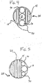
- An alternative to the design illustrated in Figures 1 and 1a is to rotate the CBP 90 degrees, as shown in Figure 4, such that the tubes 30 are adjacent to the nozzle 10 but only above and below the nozzle 10 with the vanes 15 deflecting air 35 horizontally from the flame. This would be beneficial for burners adjacent to the sidewall of the furnace, in order to protect the sidewall from corrosion or slagging by directing air along it.
- FIG. 5 Another alternative, to the embodiment of Figures 2 and 2a, is to rotate the CBP 90 degrees, as shown in Figure 5, such that the burner nozzle 10 is on the horizontal centreline at the edge of the throat 25 with the air tubes 30 adjacent to it, and with the air vanes 15 directing air horizontally away from the flame. Again, this would be beneficial for burners adjacent to sidewalls by directing air along the sidewall to prevent slagging or corrosion.
- the air tubes could similarly be reshaped to better fit the cavity adjacent to the coal nozzle.
- the air tubes could be equipped with vanes to deflect the air toward the fuel jet to accelerate mixing, rather than using swirling air as previously described.
- CBPs at multiple elevations of burners to enhance NO x reduction, rather than just at the top burner elevation. Elevated furnace temperatures in the burner zone and high coal reactivity could support two or more elevations of CBPs with satisfactory flame stability.
- the coal nozzle can be equipped with an oil atomizer to enable oil firing with the CBP.
- Oil combustion would be facilitated by the use of grouped-hole sprayer tips, which produce a "butterfly" or rectangular flame, more compatible with the design of the CBP.
- Natural gas can be fired through a gas element located inside the coal nozzle, in place of the oil atomizer, or alternatively, by multiple spuds in the cavity adjacent to the coal nozzle and through or between the air tubes. Gas firing would be facilitated by directional spuds for patterning the gas flame to be compatible with the CBP, similarly to oil firing.
- a final alternative is to use actual NO x ports positioned above the CBPs, for a second level of air staging for further reducing NO x . That is, the CBP does not necessarily eliminate the potential for additional air staging for situations which would accommodate this and require the lowest level of NO x emissions.
Landscapes
- Engineering & Computer Science (AREA)
- Chemical & Material Sciences (AREA)
- Combustion & Propulsion (AREA)
- Mechanical Engineering (AREA)
- General Engineering & Computer Science (AREA)
- Combustion Of Fluid Fuel (AREA)
Applications Claiming Priority (2)
| Application Number | Priority Date | Filing Date | Title |
|---|---|---|---|
| US08/116,312 US5329866A (en) | 1993-09-03 | 1993-09-03 | Combined low NOx burner and NOx port |
| US116312 | 1993-09-03 |
Publications (2)
| Publication Number | Publication Date |
|---|---|
| EP0641970A2 true EP0641970A2 (fr) | 1995-03-08 |
| EP0641970A3 EP0641970A3 (fr) | 1995-08-16 |
Family
ID=22366444
Family Applications (1)
| Application Number | Title | Priority Date | Filing Date |
|---|---|---|---|
| EP94301959A Withdrawn EP0641970A3 (fr) | 1993-09-03 | 1994-03-18 | Brûleurs et orifices d'admission d'air combinés. |
Country Status (6)
| Country | Link |
|---|---|
| US (1) | US5329866A (fr) |
| EP (1) | EP0641970A3 (fr) |
| JP (1) | JPH0783405A (fr) |
| CN (1) | CN1100188A (fr) |
| CA (1) | CA2120903C (fr) |
| TW (1) | TW232045B (fr) |
Families Citing this family (11)
| Publication number | Priority date | Publication date | Assignee | Title |
|---|---|---|---|---|
| FR2713312B1 (fr) * | 1993-11-30 | 1996-01-12 | Air Liquide | Brûleur oxycombustible agencé pour réduire la formation d'oxydes d'azote et particulièrement destiné aux fours de verrerie. |
| US5771823A (en) * | 1996-01-31 | 1998-06-30 | Aep Resources Service Company | Method and apparatus for reducing NOx emissions from a multiple-intertube pulverized-coal burner |
| US5746143A (en) * | 1996-02-06 | 1998-05-05 | Vatsky; Joel | Combustion system for a coal-fired furnace having an air nozzle for discharging air along the inner surface of a furnace wall |
| US6148743A (en) * | 1996-04-29 | 2000-11-21 | Foster Wheeler Corporation | Air nozzle for a furnace |
| US5809913A (en) * | 1996-10-15 | 1998-09-22 | Cinergy Technology, Inc. | Corrosion protection for utility boiler side walls |
| EP1219893B1 (fr) * | 1998-07-29 | 2006-01-18 | Mitsubishi Heavy Industries, Ltd. | Brûleur à charbon pulvérisé |
| US7624707B2 (en) * | 2004-01-29 | 2009-12-01 | Babcock & Wilcox Power Generation Group, Inc. | Re-oriented over fire air ports for reduction of NOx production from pulverized coal-fired burners |
| CN1873325B (zh) * | 2005-05-31 | 2013-05-29 | 巴布考克及威尔考克斯公司 | 减少从燃烧煤粉燃烧器中产生nox产物的重定向过热空气口 |
| EP1731832A1 (fr) * | 2005-06-11 | 2006-12-13 | Vattenfall Europe Generation AG & Co. KG | Arrangement d'un brûleur à jet pour la combustion du charbon pulvérisé dans une chambre de combustion à émission réduite de NOx |
| US7775791B2 (en) * | 2008-02-25 | 2010-08-17 | General Electric Company | Method and apparatus for staged combustion of air and fuel |
| JP6041662B2 (ja) * | 2012-12-20 | 2016-12-14 | 大阪瓦斯株式会社 | 粉体燃焼装置 |
Family Cites Families (6)
| Publication number | Priority date | Publication date | Assignee | Title |
|---|---|---|---|---|
| US4520739A (en) * | 1982-07-12 | 1985-06-04 | Combustion Engineering, Inc. | Nozzle tip for pulverized coal burner |
| JPS60226609A (ja) * | 1984-04-23 | 1985-11-11 | Babcock Hitachi Kk | 燃焼装置 |
| EP0445938B1 (fr) * | 1990-03-07 | 1996-06-26 | Hitachi, Ltd. | Brûleur à charbon pulvérisé, chaudière au charbon pulvérisé et procédé pour la combustion de charbon pulvérisé |
| US5195450A (en) * | 1990-10-31 | 1993-03-23 | Combustion Engineering, Inc. | Advanced overfire air system for NOx control |
| US5199355A (en) * | 1991-08-23 | 1993-04-06 | The Babcock & Wilcox Company | Low nox short flame burner |
| US5205226A (en) * | 1992-03-13 | 1993-04-27 | The Babcock & Wilcox Company | Low NOx burner system |
-
1993
- 1993-09-03 US US08/116,312 patent/US5329866A/en not_active Expired - Fee Related
-
1994
- 1994-03-18 EP EP94301959A patent/EP0641970A3/fr not_active Withdrawn
- 1994-03-30 TW TW083102784A patent/TW232045B/zh active
- 1994-04-08 CA CA002120903A patent/CA2120903C/fr not_active Expired - Fee Related
- 1994-04-25 CN CN94104867.5A patent/CN1100188A/zh active Pending
- 1994-08-26 JP JP6223965A patent/JPH0783405A/ja active Pending
Also Published As
| Publication number | Publication date |
|---|---|
| US5329866A (en) | 1994-07-19 |
| CA2120903A1 (fr) | 1995-03-04 |
| CA2120903C (fr) | 1996-09-24 |
| JPH0783405A (ja) | 1995-03-28 |
| CN1100188A (zh) | 1995-03-15 |
| TW232045B (en) | 1994-10-11 |
| EP0641970A3 (fr) | 1995-08-16 |
Similar Documents
| Publication | Publication Date | Title |
|---|---|---|
| AU2003237815B2 (en) | Low nox combustion | |
| US6699030B2 (en) | Combustion in a multiburner furnace with selective flow of oxygen | |
| US5799594A (en) | Method and apparatus for reducing nitrogen oxide emissions from burning pulverized fuel | |
| EP0529779B1 (fr) | Brûleurs avec production minime de NOx | |
| JP4969015B2 (ja) | 固体燃料バーナと固体燃料バーナを用いた燃焼方法 | |
| US4708638A (en) | Fluid fuel fired burner | |
| EP1416221A1 (fr) | Combustion avec reduction de Nox de courants de charbon concentres | |
| US4715301A (en) | Low excess air tangential firing system | |
| EP1192390B1 (fr) | Procede de commande d'un systeme de cuisson tangentielle | |
| CN1246177A (zh) | 改进的粉煤燃烧器 | |
| US10352555B2 (en) | Low-NOx-burner | |
| US5727480A (en) | Over-fire air control system for a pulverized solid fuel furnace | |
| US5329866A (en) | Combined low NOx burner and NOx port | |
| JPH0268403A (ja) | 固体燃料燃焼装置 | |
| EP0238907B1 (fr) | Combustion tangentielle à bas excédent d'air | |
| US5113771A (en) | Pulverized coal fuel injector | |
| JP6732960B2 (ja) | 燃料を燃焼させる方法及びボイラー | |
| HUT65491A (en) | An advanced overfire air system for nox control and method for controlling nox in fossil fuel furnaces | |
| US5899172A (en) | Separated overfire air injection for dual-chambered furnaces | |
| IL171017A (en) | High set separated overfire air system for pulverized coal fired furnace | |
| US4614492A (en) | Burner for burning pulverulent fuel | |
| CN212362003U (zh) | W火焰锅炉 |
Legal Events
| Date | Code | Title | Description |
|---|---|---|---|
| PUAI | Public reference made under article 153(3) epc to a published international application that has entered the european phase |
Free format text: ORIGINAL CODE: 0009012 |
|
| AK | Designated contracting states |
Kind code of ref document: A2 Designated state(s): DE ES FR GB IT |
|
| PUAL | Search report despatched |
Free format text: ORIGINAL CODE: 0009013 |
|
| AK | Designated contracting states |
Kind code of ref document: A3 Designated state(s): DE ES FR GB IT |
|
| 17P | Request for examination filed |
Effective date: 19960116 |
|
| STAA | Information on the status of an ep patent application or granted ep patent |
Free format text: STATUS: THE APPLICATION HAS BEEN WITHDRAWN |
|
| 18W | Application withdrawn |
Withdrawal date: 19970501 |