EP0641990B1 - Behälter zur Verpackung eines Artikels mit funkelektrischer Übertragungsvorrichtung und abnehmbares Element dazu - Google Patents
Behälter zur Verpackung eines Artikels mit funkelektrischer Übertragungsvorrichtung und abnehmbares Element dazu Download PDFInfo
- Publication number
- EP0641990B1 EP0641990B1 EP94401822A EP94401822A EP0641990B1 EP 0641990 B1 EP0641990 B1 EP 0641990B1 EP 94401822 A EP94401822 A EP 94401822A EP 94401822 A EP94401822 A EP 94401822A EP 0641990 B1 EP0641990 B1 EP 0641990B1
- Authority
- EP
- European Patent Office
- Prior art keywords
- container
- removable element
- radio frequency
- antenna
- aperture
- Prior art date
- Legal status (The legal status is an assumption and is not a legal conclusion. Google has not performed a legal analysis and makes no representation as to the accuracy of the status listed.)
- Expired - Lifetime
Links
- 230000005540 biological transmission Effects 0.000 title claims abstract description 24
- 238000004806 packaging method and process Methods 0.000 title claims abstract description 9
- 238000010304 firing Methods 0.000 description 3
- 238000012550 audit Methods 0.000 description 2
- 230000008878 coupling Effects 0.000 description 2
- 238000010168 coupling process Methods 0.000 description 2
- 238000005859 coupling reaction Methods 0.000 description 2
- 230000006378 damage Effects 0.000 description 2
- 235000015842 Hesperis Nutrition 0.000 description 1
- 235000012633 Iberis amara Nutrition 0.000 description 1
- 238000004804 winding Methods 0.000 description 1
Images

Classifications
-
- F—MECHANICAL ENGINEERING; LIGHTING; HEATING; WEAPONS; BLASTING
- F42—AMMUNITION; BLASTING
- F42B—EXPLOSIVE CHARGES, e.g. FOR BLASTING, FIREWORKS, AMMUNITION
- F42B39/00—Packaging or storage of ammunition or explosive charges; Safety features thereof; Cartridge belts or bags
-
- F—MECHANICAL ENGINEERING; LIGHTING; HEATING; WEAPONS; BLASTING
- F41—WEAPONS
- F41F—APPARATUS FOR LAUNCHING PROJECTILES OR MISSILES FROM BARRELS, e.g. CANNONS; LAUNCHERS FOR ROCKETS OR TORPEDOES; HARPOON GUNS
- F41F3/00—Rocket or torpedo launchers
- F41F3/04—Rocket or torpedo launchers for rockets
- F41F3/042—Rocket or torpedo launchers for rockets the launching apparatus being used also as a transport container for the rocket
Definitions
- the present invention relates to a container for packaging of an object provided with a radio transmission device and a removable element for such a container.
- the present invention particularly applies to the case where said object is a missile. It will be explained below in relationship with such an object.
- a missile When wrapped in its packaging, a missile must ability to communicate with an external control station, either to transmit information such as telemetry before firing or testing, either for receive information, such as fire order, trajectory to follow, order of remote destruction, etc ... To this effect it is natural to use the transmission device radioelectric which is provided with said missile.
- the object of the present invention is to remedy these drawbacks.
- any external control station can be in radio link with the device radio transmission linked to said object (missile), so to exchange information, said radio antenna of the removable element ensuring the connection with said device radio transmission.
- said element is removable, several interchangeable removable elements can be provided, each specifically adapted to a particular missile and / or at a particular phase in the life of a missile (experimentation, development, storage, waiting for firing, etc ).
- said removable elements can be manufactured and placed point, regardless of the containers, which is an ease.
- the container according to the present invention may include moreover a simple plug likely to take the place of said removable element in said opening, for periods when radio links are not required.
- Said opening may be any already existing opening of the container.
- the opening for receive said removable element (and / or said plug) is specifically fitted for said removable element.
- it is made in the upper wall of said container.
- the present invention further relates to an element removable for closing a container opening intended for the packaging of an object provided with a device for radio transmission.
- a removable element is remarkable in that it carries, on one side, at least one radio antenna and, on the other side, at least one coaxial connector, said antenna and said connector coaxial being electrically connected to each other, so that when said removable element is in the closed position from said opening, said coaxial connector is accessible from outside of said container, while said antenna is inside said container and is susceptible to be radio-coupled with said device radio transmission of said object wrapped in said container.
- said removable element comprises a shutter, capable of closing said opening and provided with said coaxial connector which passes through it, and a plate, integral with said shutter and carrying said radio antenna, this plate being susceptible to pass through said opening, so that be introduced inside said container, when the shutter is placed on said opening, or in be out, when said shutter is released from said opening.
- said shutter is cylindrical and said plate is integral with the end face interior of said shutter.
- Said coaxial connector then crosses a transverse wall of said cylindrical shutter and is fixed on this last.
- said plate is arranged radially with respect to said shutter and said antenna is arranged on the face of said plate intended to be located, in closed position of said removable element, opposite said object.
- the other opposite face of said plate can carry the circuit of said antenna.
- said removable element comprises a plurality of radio antennas each corresponding to a specific radio transmission (telemetry, remote destruction, teletrajectography, etc.) and a number equal of coaxial connectors, respectively associated to said antennas.
- These coaxial connectors can be different dimensions.
- the transverse wall of said cylindrical shutter on which said said are fixed coaxial connectors may not be planar, but at otherwise present different levels, in order to accommodate the better said coaxial connectors in said shutter.
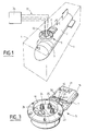
- Figure 1 schematically illustrates a container according to the present invention, equipped with a removable element also according to the present invention.
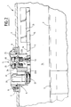
- Figure 2 is a partial section along line II-II of container of Figure 1, showing said removable element in section shown on a wall of said container.
- Figure 3 is a perspective view from above of the element removable according to the invention.
- Figure 4 is a bottom view of said removable element.
- Container 1 shown schematically in dashed lines on Figure 1, encloses a missile 2 equipped with a device for radio transmission, of which only the one (s) antennas 3 has (have) been shown.
- a removable element 5 is fixed on a wall 4 of said container 1, for example the wall upper.
- said wall 4 is pierced with an opening 6, for example bordered by a flange 7, and on which can be fixed said removable element 5, for example by means of screws 8 (see figure 2).
- a seal 9 seals this fixation.
- said removable element 5 consists of a cylindrical shutter 10, intended to cooperate with the flange 7 to close said opening 6, and of a projecting radial plate 11, fixed to the face inner end 12 of said shutter 10, for example by means of screws 13.
- the width l of said radial plate 11 is smaller than the diameter of the opening 6, so that it can pass through said opening 6 to be introduced inside the container 1, or be removed therefrom.
- antennas radio stations 17, 18, 19 and 20 On the face 15 of the wafer 11, are arranged antennas radio stations 17, 18, 19 and 20, while on the face 16 of said plate 11, the circuits are arranged said antennas, protected by a cover 21.
- transverse 22 on which are fixed coaxial sockets through 23, 24, 25 and 26.
- the transverse wall 22 is not planar, but has bleachers.
- the coaxial socket 26 is larger than the sockets coaxial 23, 24 and 25 and that the part 22A of the wall 22 on which it is fixed is deeper than the part 22B on which the coaxial sockets 23, 24 and 25.
- the through coaxial sockets 23 to 26 are fixed by clamping nuts 27, cooperating with their threaded body.
- removable plugs 28 are provided to seal the external ends of the sockets coaxial 23 to 26.
- coaxial links 29 to 32 (not shown in Figure 2, but partially visible in the Figure 3 and only illustrated in Figure 4 by dashed lines for clarity of the drawing) connect each of the electrodes 17 to 20 to the coaxial socket 23 to 26 corresponding.
- coaxial sockets 23 to 26 are accessible from the outside and can therefore be connected, by cables coaxial 33 (only shown in dotted lines on the figure 1), at any transmitting and / or receiving station radioelectric 34, outside said container 1.
- the removable element 5 is specific to the radio transmission device carried by missile 2.
- a removable element 5 can be used, whatever the container 1 and the missile 2, provided that this element 5 can cooperate with the transmission device carried by said missile.
- several removable elements are provided 5, which can be interchangeably mounted on a container 1, it is possible either to use said container to pack several different types of missiles 2, whose transmission devices are respectively adapted to said removable elements 5, or to produce different specific radio links between a same missile 2 and station 34.
- the opening 6 can be specially provided on container 1 to receive the element removable 5, or the shutter 10 of said element removable 5 can be adapted to be able to close an opening 6 already existing on said container 1 for another use.
Landscapes
- Engineering & Computer Science (AREA)
- General Engineering & Computer Science (AREA)
- Packages (AREA)
- Auxiliary Devices For And Details Of Packaging Control (AREA)
- Closures For Containers (AREA)
- Burglar Alarm Systems (AREA)
- Structure Of Receivers (AREA)
- Radar Systems Or Details Thereof (AREA)
- Aiming, Guidance, Guns With A Light Source, Armor, Camouflage, And Targets (AREA)
- Details Of Aerials (AREA)
Claims (11)
- Behälter (1) zur Verpackung eines Gegenstandes (2) mit einer funkelektrischen Übertragungsvorrichtung mit einer Schnittstelle, die einerseits mit dem Gegenstand (2) verbunden ist und andererseits einen von außerhalb des Behälters (1) zugänglichen Verbinder hat,
dadurch gekennzeichnet, daßdie Schnittstelle ein abnehmbares Element (5) ist, das eine Öffnung (6) von Behälter (1) verschließen kann und an dem sich einerseits mindestens eine funkelektrische Antenne (17 bis 20) und andererseits mindestens ein Verbinder (23 bis 26) des koaxialen Typs befinden, wobei die Antenne und der koaxiale Verbinder elektrisch miteinander verbunden sind; undder koaxiale Verbinder (23 bis 26), wenn sich das abnehmbare Element (5) in Verschlußstellung der Öffnung (6) befindet, von außerhalb des Behälters (1) zugänglich ist, während sich die Antenne (17 bis 20) innerhalb des Behälters befindet und funkelektrisch mit der funkelektrischen Übertragungsvorrichtung des Gegenstandes (2) im Behälter (1) gekoppelt werden kann. - Behälter nach Anspruch 1,
dadurch gekennzeichnet, daß die Öffnung (6) speziell für das abnehmbare Element (5) vorgesehen ist. - Behälter nach einem der Ansprüche 1 oder 2,
dadurch gekennzeichnet, daß die Öffnung (6) in der oberen Wand (4) des Behälters vorgesehen ist. - Behälter nach einem der Ansprüche 1 bis 3,
dadurch gekennzeichnet, daß er einen einfachen Stöpsel hat, der das abnehmbare Element in der Öffnung ersetzen kann, wenn keine funkelektrischen Verbindungen benötigt werden. - Abnehmbares Element (5) zum Verschließen einer Öffnung (6) eines Behälters (1) zur Verpackung eines Gegenstands (2) mit einer funkelektrischen Übertragungsvorrichtung,
dadurch gekennzeichnet, daß es einerseits mindestens eine funkelektrische Antenne (17 bis 20) und andererseits mindestens einen koaxialen Verbinder (23 bis 26) hat, wobei die Antenne und der koaxiale Verbinder elektrisch miteinander verbunden sind, so daß der koaxiale Verbinder (23 bis 26), wenn sich das abnehmbare Element (5) in Verschlußstellung der Öffnung (6) befindet, von außerhalb des Behälters (1) zugänglich ist, während sich die Antenne (17 bis 20) innerhalb des Behälters befindet und funkelektrisch mit der funkelektrischen Übertragungsvorrichtung des Gegenstands (2) im Behälter (1) gekoppelt werden kann. - Abnehmbares Element nach Anspruch 5,
dadurch gekennzeichnet, daß es einen Verschluß (10) hat, der die Öffnung (6) verschließen kann und der mit dem durch das Element verlaufenden koaxialen Verbinder (23 bis 26) und einer Platte (11) versehen ist, die mit dem Verschluß (10) verbunden ist und auf der sich die funkelektrische Antenne (17 bis 20) befindet, wobei die Abmessungen der Platte (11) derart sind, daß sie durch die Öffnung (6) gelangen kann. - Abnehmbares Element nach Anspruch 6,
dadurch gekennzeichnet, daß der Verschluß (10) zylindrisch ist und die Platte (11) mit der inneren Endfläche (12) des Verschlusses (10) verbunden ist. - Abnehmbares Element nach einem der Ansprüche 6 oder 7,
dadurch gekennzeichnet, daß die Platte (11) radial zum Verschluß (10) angeordnet ist. - Abnehmbares Element nach einem der Ansprüche 6 bis 8,
dadurch gekennzeichnet, daß die Antenne (17 bis 20) auf der Seite (15) der Platte (11) angeordnet ist, die sich in Verschlußstellung des abnehmbaren Elements gegenüber dem Gegenstand (2) befindet. - Abnehmbares Element nach Anspruch 9,
dadurch gekennzeichnet, daß sich auf der Seite (16) von Platte (11) entgegengesetzt zu Seite (15) gegenüber Gegenstand (2) der Stromkreis der Antenne (17 bis 20) befindet. - Abnehmbares Element nach einem der Ansprüche 5 bis 10,
dadurch gekennzeichnet, daß es mehrere funkelektrische Antennen (17 bis 20) jeweils für eine spezifische funkelektrische Übertragung und eine gleiche Anzahl koaxialer Verbinder jeweils für die Antennen hat.
Applications Claiming Priority (2)
| Application Number | Priority Date | Filing Date | Title |
|---|---|---|---|
| FR9310556 | 1993-09-06 | ||
| FR9310556A FR2709875B1 (fr) | 1993-09-06 | 1993-09-06 | Conteneur pour l'emballage d'un objet pourvu d'un dispositif de transmission radioélectrique et élément amovible pour un tel conteneur. |
Publications (2)
| Publication Number | Publication Date |
|---|---|
| EP0641990A1 EP0641990A1 (de) | 1995-03-08 |
| EP0641990B1 true EP0641990B1 (de) | 1998-07-08 |
Family
ID=9450572
Family Applications (1)
| Application Number | Title | Priority Date | Filing Date |
|---|---|---|---|
| EP94401822A Expired - Lifetime EP0641990B1 (de) | 1993-09-06 | 1994-08-08 | Behälter zur Verpackung eines Artikels mit funkelektrischer Übertragungsvorrichtung und abnehmbares Element dazu |
Country Status (8)
| Country | Link |
|---|---|
| US (1) | US5458042A (de) |
| EP (1) | EP0641990B1 (de) |
| JP (1) | JPH07239200A (de) |
| AT (1) | ATE168187T1 (de) |
| CA (1) | CA2117621A1 (de) |
| DE (1) | DE69411472T2 (de) |
| ES (1) | ES2119108T3 (de) |
| FR (1) | FR2709875B1 (de) |
Families Citing this family (8)
| Publication number | Priority date | Publication date | Assignee | Title |
|---|---|---|---|---|
| US5600087A (en) * | 1995-03-21 | 1997-02-04 | Sippican, Inc. | Field programmable expendable underwater vehicle |
| US6041688A (en) * | 1996-06-25 | 2000-03-28 | Raytheon Company | Wireless guided missile launch container |
| US9127908B2 (en) | 2009-02-02 | 2015-09-08 | Aero Vironment, Inc. | Multimode unmanned aerial vehicle |
| WO2011066031A2 (en) | 2009-09-09 | 2011-06-03 | Aerovironment, Inc. | Elevon control system |
| JP5865247B2 (ja) * | 2009-09-09 | 2016-02-17 | エアロバイロメント, インコーポレイテッドAerovironment, Inc. | 可搬型rf透過性発射筒を有する遠隔操作無人航空機レポート抑制発射機のためのシステムおよび装置 |
| US20110291828A1 (en) * | 2010-06-01 | 2011-12-01 | Walker Timothy A | Embedded communication system for refrigerated transportation containers |
| CN112833707B (zh) * | 2021-01-04 | 2023-09-08 | 中国人民解放军海军航空大学岸防兵学院 | 导弹发射箱 |
| CN113002807A (zh) * | 2021-02-07 | 2021-06-22 | 上海交通大学 | 一种用于火箭推进剂自动加注的管道装置 |
Family Cites Families (9)
| Publication number | Priority date | Publication date | Assignee | Title |
|---|---|---|---|---|
| US4307665A (en) * | 1965-12-21 | 1981-12-29 | General Dynamics Corporation | Decoy rounds |
| US3371579A (en) * | 1966-12-12 | 1968-03-05 | Army Usa | Failsafe fuze-setting system |
| US4137819A (en) * | 1977-11-28 | 1979-02-06 | The United States Of America As Represented By The Secretary Of The Army | Launch tube antenna |
| FR2431673A1 (fr) * | 1978-07-21 | 1980-02-15 | Thomson Brandt | Lance-roquettes |
| US4318342A (en) * | 1980-01-25 | 1982-03-09 | Aai Corporation | Ammunition with surface-mounted light-settable pickup arrangement for digital memory storage |
| DE3150172A1 (de) * | 1981-12-18 | 1983-06-30 | Brown, Boveri & Cie Ag, 6800 Mannheim | Einrichtung zum einstellen und/oder ueberwachen der wirkungsweise eines geschosszuenders |
| US4444087A (en) * | 1982-01-28 | 1984-04-24 | The Boeing Company | Missile container and extraction mechanism |
| US4649796A (en) * | 1986-06-18 | 1987-03-17 | The United States Of America As Represented By The Secretary Of The Army | Method and apparatus for setting a projectile fuze during muzzle exit |
| US5160801A (en) * | 1991-05-20 | 1992-11-03 | Alliant Techsystems Inc. | Powerless programmable fuze function mode system |
-
1993
- 1993-09-06 FR FR9310556A patent/FR2709875B1/fr not_active Expired - Fee Related
-
1994
- 1994-08-08 AT AT94401822T patent/ATE168187T1/de active
- 1994-08-08 DE DE69411472T patent/DE69411472T2/de not_active Expired - Fee Related
- 1994-08-08 EP EP94401822A patent/EP0641990B1/de not_active Expired - Lifetime
- 1994-08-08 ES ES94401822T patent/ES2119108T3/es not_active Expired - Lifetime
- 1994-09-01 CA CA002117621A patent/CA2117621A1/fr not_active Abandoned
- 1994-09-02 JP JP6209909A patent/JPH07239200A/ja active Pending
- 1994-09-02 US US08/300,634 patent/US5458042A/en not_active Expired - Fee Related
Also Published As
| Publication number | Publication date |
|---|---|
| DE69411472D1 (de) | 1998-08-13 |
| CA2117621A1 (fr) | 1995-03-07 |
| US5458042A (en) | 1995-10-17 |
| ATE168187T1 (de) | 1998-07-15 |
| ES2119108T3 (es) | 1998-10-01 |
| FR2709875B1 (fr) | 1995-11-24 |
| EP0641990A1 (de) | 1995-03-08 |
| JPH07239200A (ja) | 1995-09-12 |
| FR2709875A1 (fr) | 1995-03-17 |
| DE69411472T2 (de) | 1998-12-24 |
Similar Documents
| Publication | Publication Date | Title |
|---|---|---|
| EP0580505B1 (de) | Anpassungssystem zwischen einem Antennenstecker und der Buchse eines Funktelefons | |
| EP0641990B1 (de) | Behälter zur Verpackung eines Artikels mit funkelektrischer Übertragungsvorrichtung und abnehmbares Element dazu | |
| EP0619625B1 (de) | Elektrischer Verbinder mit einer Anzahl von Modulen in Reihen und Kolonnen geordnet | |
| EP0619626B1 (de) | Elektrischer Verbinder mit einer Anzahl von Steckmodulen | |
| FR2476402A1 (fr) | Boitier d'epissure etanche de cables | |
| EP1405003A1 (de) | Anordnung zum verbinden und trennen zweier rohrabschnitte eines fluidübertragungssystems | |
| EP1612139B1 (de) | Vorrichtung und Verfahren zur Befestigung eines Flugzeug-Radoms | |
| FR2809991A3 (fr) | Dispositif d'attelage pour connecter une remorque a un vehicule automobile | |
| EP0088664B1 (de) | Kopplungsvorrichtung zwischen zwei Mikrowellenhohlleiter | |
| FR3079024A1 (fr) | Conteneur pour modules de poudre propulsive | |
| EP0902997B1 (de) | Vorrichtung zum montieren wenigstens eines kabels in eine scheibe,welche zum positionieren in eine schutzmuffe einer kabelverbindung bestimmt ist | |
| FR2989524A1 (fr) | Systeme de connexion monovoie rapide | |
| EP1376045B1 (de) | Vorrichtung zum Adaptieren eines aus einem Rohr abzuschiessenden Projektils | |
| FR2692727A1 (fr) | Connecteur pour borne de batterie. | |
| FR2686461A1 (fr) | Dispositif de raccordement electrique etanche. | |
| BE1015204A3 (fr) | Connectique entre un lanceur militaire et des munitions resistant a l'encrassage. | |
| EP1351343B1 (de) | Elektrisches Gerät mit einem Schnellanschluss an die Spannungsversorgung, besonders geeignet für wasserdichte Lampenfassungen | |
| EP3709445A1 (de) | Elektrischer schalter für elektrisches gerät | |
| FR2537791A1 (fr) | Dispositif de derivation pour cables electriques | |
| FR2496349A1 (fr) | Dispositif pour le support d'objets allonges tels que cables, faisceaux de cables ou analogues et installations comportant de tels dispositifs | |
| EP0599673A1 (de) | Verbinderhülse für abgedichtete Durchführung und dazugehörige Anordnung | |
| EP0654857A1 (de) | Elektrischen Steckanschluss mit ausklappbarer Verschlussblende | |
| FR2522884A1 (fr) | Joint tournant haute frequence | |
| EP0170547B1 (de) | Antennenanordnungen | |
| FR2673697A1 (fr) | Dispositif d'orientation de cable. |
Legal Events
| Date | Code | Title | Description |
|---|---|---|---|
| PUAI | Public reference made under article 153(3) epc to a published international application that has entered the european phase |
Free format text: ORIGINAL CODE: 0009012 |
|
| AK | Designated contracting states |
Kind code of ref document: A1 Designated state(s): AT BE CH DE ES GB GR IE IT LI NL PT SE |
|
| 17P | Request for examination filed |
Effective date: 19950329 |
|
| 17Q | First examination report despatched |
Effective date: 19961114 |
|
| GRAG | Despatch of communication of intention to grant |
Free format text: ORIGINAL CODE: EPIDOS AGRA |
|
| GRAG | Despatch of communication of intention to grant |
Free format text: ORIGINAL CODE: EPIDOS AGRA |
|
| GRAH | Despatch of communication of intention to grant a patent |
Free format text: ORIGINAL CODE: EPIDOS IGRA |
|
| GRAH | Despatch of communication of intention to grant a patent |
Free format text: ORIGINAL CODE: EPIDOS IGRA |
|
| GRAA | (expected) grant |
Free format text: ORIGINAL CODE: 0009210 |
|
| AK | Designated contracting states |
Kind code of ref document: B1 Designated state(s): AT BE CH DE ES GB GR IE IT LI NL PT SE |
|
| PG25 | Lapsed in a contracting state [announced via postgrant information from national office to epo] |
Ref country code: GR Free format text: LAPSE BECAUSE OF FAILURE TO SUBMIT A TRANSLATION OF THE DESCRIPTION OR TO PAY THE FEE WITHIN THE PRESCRIBED TIME-LIMIT Effective date: 19980708 Ref country code: AT Free format text: LAPSE BECAUSE OF FAILURE TO SUBMIT A TRANSLATION OF THE DESCRIPTION OR TO PAY THE FEE WITHIN THE PRESCRIBED TIME-LIMIT Effective date: 19980708 |
|
| REF | Corresponds to: |
Ref document number: 168187 Country of ref document: AT Date of ref document: 19980715 Kind code of ref document: T |
|
| REG | Reference to a national code |
Ref country code: CH Ref legal event code: NV Representative=s name: JOHN P. MUNZINGER INGENIEUR-CONSEIL Ref country code: CH Ref legal event code: EP |
|
| GBT | Gb: translation of ep patent filed (gb section 77(6)(a)/1977) |
Effective date: 19980710 |
|
| REF | Corresponds to: |
Ref document number: 69411472 Country of ref document: DE Date of ref document: 19980813 |
|
| REG | Reference to a national code |
Ref country code: ES Ref legal event code: FG2A Ref document number: 2119108 Country of ref document: ES Kind code of ref document: T3 |
|
| REG | Reference to a national code |
Ref country code: IE Ref legal event code: FG4D Free format text: FRENCH |
|
| PG25 | Lapsed in a contracting state [announced via postgrant information from national office to epo] |
Ref country code: PT Free format text: LAPSE BECAUSE OF FAILURE TO SUBMIT A TRANSLATION OF THE DESCRIPTION OR TO PAY THE FEE WITHIN THE PRESCRIBED TIME-LIMIT Effective date: 19981008 |
|
| PG25 | Lapsed in a contracting state [announced via postgrant information from national office to epo] |
Ref country code: IE Free format text: LAPSE BECAUSE OF NON-PAYMENT OF DUE FEES Effective date: 19990219 |
|
| REG | Reference to a national code |
Ref country code: IE Ref legal event code: FD4D |
|
| PLBE | No opposition filed within time limit |
Free format text: ORIGINAL CODE: 0009261 |
|
| STAA | Information on the status of an ep patent application or granted ep patent |
Free format text: STATUS: NO OPPOSITION FILED WITHIN TIME LIMIT |
|
| 26N | No opposition filed | ||
| REG | Reference to a national code |
Ref country code: GB Ref legal event code: IF02 |
|
| PGFP | Annual fee paid to national office [announced via postgrant information from national office to epo] |
Ref country code: CH Payment date: 20020703 Year of fee payment: 9 |
|
| PGFP | Annual fee paid to national office [announced via postgrant information from national office to epo] |
Ref country code: SE Payment date: 20020715 Year of fee payment: 9 |
|
| PGFP | Annual fee paid to national office [announced via postgrant information from national office to epo] |
Ref country code: BE Payment date: 20020718 Year of fee payment: 9 |
|
| PGFP | Annual fee paid to national office [announced via postgrant information from national office to epo] |
Ref country code: ES Payment date: 20020725 Year of fee payment: 9 |
|
| PGFP | Annual fee paid to national office [announced via postgrant information from national office to epo] |
Ref country code: DE Payment date: 20020731 Year of fee payment: 9 |
|
| PGFP | Annual fee paid to national office [announced via postgrant information from national office to epo] |
Ref country code: NL Payment date: 20020830 Year of fee payment: 9 |
|
| PG25 | Lapsed in a contracting state [announced via postgrant information from national office to epo] |
Ref country code: SE Free format text: LAPSE BECAUSE OF NON-PAYMENT OF DUE FEES Effective date: 20030809 Ref country code: ES Free format text: LAPSE BECAUSE OF NON-PAYMENT OF DUE FEES Effective date: 20030809 |
|
| PG25 | Lapsed in a contracting state [announced via postgrant information from national office to epo] |
Ref country code: LI Free format text: LAPSE BECAUSE OF NON-PAYMENT OF DUE FEES Effective date: 20030831 Ref country code: CH Free format text: LAPSE BECAUSE OF NON-PAYMENT OF DUE FEES Effective date: 20030831 Ref country code: BE Free format text: LAPSE BECAUSE OF NON-PAYMENT OF DUE FEES Effective date: 20030831 |
|
| BERE | Be: lapsed |
Owner name: *AEROSPATIALE SOC. NATIONALE INDUSTRIELLE Effective date: 20030831 |
|
| PG25 | Lapsed in a contracting state [announced via postgrant information from national office to epo] |
Ref country code: NL Free format text: LAPSE BECAUSE OF NON-PAYMENT OF DUE FEES Effective date: 20040301 |
|
| PG25 | Lapsed in a contracting state [announced via postgrant information from national office to epo] |
Ref country code: DE Free format text: LAPSE BECAUSE OF NON-PAYMENT OF DUE FEES Effective date: 20040302 |
|
| EUG | Se: european patent has lapsed | ||
| REG | Reference to a national code |
Ref country code: CH Ref legal event code: PL |
|
| NLV4 | Nl: lapsed or anulled due to non-payment of the annual fee |
Effective date: 20040301 |
|
| REG | Reference to a national code |
Ref country code: ES Ref legal event code: FD2A Effective date: 20030809 |
|
| PGFP | Annual fee paid to national office [announced via postgrant information from national office to epo] |
Ref country code: GB Payment date: 20060802 Year of fee payment: 13 |
|
| PGFP | Annual fee paid to national office [announced via postgrant information from national office to epo] |
Ref country code: IT Payment date: 20060831 Year of fee payment: 13 |
|
| GBPC | Gb: european patent ceased through non-payment of renewal fee |
Effective date: 20070808 |
|
| PG25 | Lapsed in a contracting state [announced via postgrant information from national office to epo] |
Ref country code: GB Free format text: LAPSE BECAUSE OF NON-PAYMENT OF DUE FEES Effective date: 20070808 |
|
| PG25 | Lapsed in a contracting state [announced via postgrant information from national office to epo] |
Ref country code: IT Free format text: LAPSE BECAUSE OF NON-PAYMENT OF DUE FEES Effective date: 20070808 |