EP0641997B1 - Kreiselpumpengehäuse mit Fördermengenmesseinrichtung - Google Patents
Kreiselpumpengehäuse mit Fördermengenmesseinrichtung Download PDFInfo
- Publication number
- EP0641997B1 EP0641997B1 EP94113251A EP94113251A EP0641997B1 EP 0641997 B1 EP0641997 B1 EP 0641997B1 EP 94113251 A EP94113251 A EP 94113251A EP 94113251 A EP94113251 A EP 94113251A EP 0641997 B1 EP0641997 B1 EP 0641997B1
- Authority
- EP
- European Patent Office
- Prior art keywords
- pressure measurement
- measurement point
- pressure
- centrifugal pump
- impeller
- Prior art date
- Legal status (The legal status is an assumption and is not a legal conclusion. Google has not performed a legal analysis and makes no representation as to the accuracy of the status listed.)
- Expired - Lifetime
Links
Images

Classifications
-
- G—PHYSICS
- G01—MEASURING; TESTING
- G01F—MEASURING VOLUME, VOLUME FLOW, MASS FLOW OR LIQUID LEVEL; METERING BY VOLUME
- G01F1/00—Measuring the volume flow or mass flow of fluid or fluent solid material wherein the fluid passes through a meter in a continuous flow
- G01F1/05—Measuring the volume flow or mass flow of fluid or fluent solid material wherein the fluid passes through a meter in a continuous flow by using mechanical effects
- G01F1/34—Measuring the volume flow or mass flow of fluid or fluent solid material wherein the fluid passes through a meter in a continuous flow by using mechanical effects by measuring pressure or differential pressure
- G01F1/36—Measuring the volume flow or mass flow of fluid or fluent solid material wherein the fluid passes through a meter in a continuous flow by using mechanical effects by measuring pressure or differential pressure the pressure or differential pressure being created by the use of flow constriction
-
- F—MECHANICAL ENGINEERING; LIGHTING; HEATING; WEAPONS; BLASTING
- F04—POSITIVE - DISPLACEMENT MACHINES FOR LIQUIDS; PUMPS FOR LIQUIDS OR ELASTIC FLUIDS
- F04D—NON-POSITIVE-DISPLACEMENT PUMPS
- F04D15/00—Control, e.g. regulation, of pumps, pumping installations or systems
- F04D15/0088—Testing machines
-
- G—PHYSICS
- G01—MEASURING; TESTING
- G01F—MEASURING VOLUME, VOLUME FLOW, MASS FLOW OR LIQUID LEVEL; METERING BY VOLUME
- G01F1/00—Measuring the volume flow or mass flow of fluid or fluent solid material wherein the fluid passes through a meter in a continuous flow
- G01F1/05—Measuring the volume flow or mass flow of fluid or fluent solid material wherein the fluid passes through a meter in a continuous flow by using mechanical effects
- G01F1/34—Measuring the volume flow or mass flow of fluid or fluent solid material wherein the fluid passes through a meter in a continuous flow by using mechanical effects by measuring pressure or differential pressure
-
- F—MECHANICAL ENGINEERING; LIGHTING; HEATING; WEAPONS; BLASTING
- F05—INDEXING SCHEMES RELATING TO ENGINES OR PUMPS IN VARIOUS SUBCLASSES OF CLASSES F01-F04
- F05D—INDEXING SCHEME FOR ASPECTS RELATING TO NON-POSITIVE-DISPLACEMENT MACHINES OR ENGINES, GAS-TURBINES OR JET-PROPULSION PLANTS
- F05D2270/00—Control
- F05D2270/30—Control parameters, e.g. input parameters
- F05D2270/301—Pressure
- F05D2270/3015—Pressure differential pressure
Definitions
- the invention relates to a centrifugal pump according to the preamble of the main claim.
- a centrifugal pump is known in which by means of a Pressure measurement in the pressure port on the flow rate is concluded.
- a first pressure measuring point in the inlet cross section of the Pressure port arranged to detect the pressure there.
- a second pressure measuring point is at a remote location in the pressure port arranged. The pressure change recorded in the pressure port is used to determine the Flow rate used.
- centrifugal pumps have connections in the area of Provide suction and pressure ports that can accommodate Pressure gauges or pressure indicators are provided. Due to the readable pressure differences Conclusions about the operating behavior of the centrifugal pump possible. For those applications, however, where one receive precise knowledge of the current flow rate would like elaborate measurement installations or conversions necessary. Another way to offer in the suction or Pressure line of a centrifugal pump integrable inductive Flow meters, which have a high accuracy, but are also very expensive.
- the invention is based on the problem in less expensive Assign the current flow rate to a centrifugal pump capture and display. This problem is solved according to the features of the main claim. It is the
- claims 9 to 14 deal with the arrangement of the pressure measuring points on the blades of a Diffuser. Here too a corresponding connection could be made be determined.
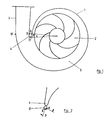
- the housing 1 shown in Fig. 1 has a spiral design an impeller 2 and a pressure nozzle 3.
- On the spur 4 are both necessary for differential pressure detection Pressure measuring points A, B, B ', B' ', arranged so that one or first measuring point A with regard to their direction of action to the impeller 2 indicates and the other or second measuring point B, B ', B' 'in the transition area between spiral 5 and discharge nozzle 3 points.
- This is a reliable detection of the different Pressures of the pumped medium influenced by the spiral possible.
- the pressure measuring point B arranged in the region of the spur can with regard to their direction of action also as a pressure measuring point B '' be aligned with the incoming medium.
- the first pressure measuring point A should point to the impeller in terms of their direction of action and within a spur starting from the center of the impeller or guide vane at the beginning of the angle ⁇ ⁇ 30 °, preferably ⁇ 17 °.
- the angle is limited by a between the center of the wheel and the The beginning of the flow around - here the spur - extending Beam; the angle opens from the center of the impeller Direction of rotation of the impeller.
- the second pressure measuring points B - B '' are provided at the locations specified in the claims. Otherwise there is no clear link between Differential pressure and flow rate available.
- the one chosen here Representation of the angle ⁇ ends exactly at the pressure measuring point A. However, since it is a schematic representation, not to see the relationships to scale.
- FIG. 2 an enlarged representation from FIG. 1, it can be seen more clearly that the two pressure measuring points A and B or B '' also part of a separate component 6 could be.
- This can form the top of the spur 4 or to be preceded by a spur.
- this component 6 as an insert from the lateral direction, for. B. from the suction side, insert into the housing 1.
- the Directions of action of those attached to it Pressure measuring points AB, AB '' close an angle between them 50 ° ⁇ ⁇ ⁇ 180 ° and thus enable the detection of Pressure differences, which is a clear statement about the Allow the respective delivery rate. This would work too a subsequent installation of such a delivery quantity measuring device allow on already installed pumps.
- FIG. 3 shows the arrangement of the pressure measuring points using the example a so-called annulus housing 7.
- the impeller 2 is here surrounded by a room of the same height and width.
- the first pressure measuring point A is located also within the starting point from the center of the impeller Angle ⁇ ⁇ 30 °. Particularly good results are in one Angular range ⁇ 17 ° can be determined.
- the angle ⁇ was here as Area shown within which the pressure measuring point located.
- This measuring principle also works Housing designs, the z. B. a combination of spiral and Represent annulus housing.
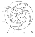
- FIG. 4 shows the arrangement using the example of a stator 10 of pressure measuring points A - B '' on guide vanes 11.
- the first pressure measuring point A is always within of the angle ⁇ is ⁇ 30 °, usually within an angle ⁇ ⁇ 17 °.
- the measuring point A can be guided within a larger one Angular range. It is also possible to have two Combine pressure measuring points with each other on different guide vanes are arranged. This is supposed to but the first pressure measuring point A within the The beginning of the blade 12 is located in the outgoing angular range ⁇ and on the side of the guide blades facing the impeller 11 to be appropriate.
- the second pressure measuring point is B, B 'or B' ' on the guide vane channel 13 facing the guide vane or on the guide blade beginning facing the direction of flow 12 arranged.
- the pressure measuring points can also be part of a the separate component 14 forming the beginning of the guide vane.
- the directions of action of the Differential pressure measuring points AB, AB '' between an angle of 50 ° ⁇ ⁇ ⁇ 180 ° to unambiguous measured values receive.
- the component 14 can be made in a simple manner Insert in the axial direction in the guide device.
- FIG. 5 shows a Q / H diagram in a dimensionless representation.
- a pump characteristic curve 15 is entered above the delivery flow Q / Q opt shown as the abscissa.
- a pressure difference ⁇ H H AB or AB 'or H AB'' which in non-dimensional representation in terms of H opt the curve 16 ⁇ H of AB / H resulting opt.
- This curve shape enables a clear and unambiguous assignment of the differential pressure ⁇ H AB to the respective delivery rate.
- the measured differential pressure can then be converted with the aid of known evaluation units into a display for an indication of the delivery quantity.
- the use of individual piezoresistive pressure transducers in their various designs has proven to be advantageous.
Landscapes
- Engineering & Computer Science (AREA)
- Physics & Mathematics (AREA)
- Fluid Mechanics (AREA)
- General Physics & Mathematics (AREA)
- Mechanical Engineering (AREA)
- General Engineering & Computer Science (AREA)
- Structures Of Non-Positive Displacement Pumps (AREA)
- Control Of Non-Positive-Displacement Pumps (AREA)
Description
- Fig. 1
- eine Anordnung der Druckmeßstellen an einem Spiralgehäuse,
- Fig. 2
- eine Vergrößerung aus Fig. 1,
- Fig. 3
- an einem Ringraumgehäuse,
- Fig. 4
- an einem Leitrad und
- Fig. 5
- den Verlauf der Druckdifferenz in Abhängigkeit vom Förderstrom.
Claims (14)
- Kreiselpumpe radialer oder halbaxialer Bauart mit dem Laufrad nachgeordneter, das Fördermedium führender Leiteinrichtung (4, 6, 9, 10, 11, 12, 13), wobei im Pumpengehäuse (1) Anschlüsse für eine Druckerfassung angebracht sind, die Druckerfassung stromab vom Laufrad (2) an zwei Druckmeßstellen (A, B, B', B") erfolgt und eine Auswerteeinheit die Druckdifferenz der beiden Druckmeßstellen in eine Fördermengenangabe umwandelt, dadurch gekennzeichnet, daß eine erste Druckmeßstelle (A) an einer dem Laufrad (2) zugekehrten Stelle der Leiteinrichtung innerhalb eines vom Laufradmittelpunkt ausgehenden, am Anfang (4, 6, 9, 12) der Leiteinrichtung beginnenden und sich im Drehsinn des Laufrads öffnenden Winkels ν < 30° angeordnet ist und daß die zweite Druckmeßstelle (B, B' oder B") an einer vom Laufrad (12) entfernten Stelle angeordnet ist.
- Kreiselpumpe nach Anspruch 1, dadurch gekennzeichnet, daß von den Druckmeßstellen (A, B, B', B'') mindestens eine an einem Sporn eines Spiralgehäuses (1) angebracht ist, wobei die erste Druckmeßstelle (A) innerhalb eines vom Laufradmittelpunkt ausgehenden und am Spornanfang beginnenden Winkels ν < 30° angeordnet ist.
- Kreiselpumpe nach Anspruch 2, dadurch gekennzeichnet, daß die erste Druckmeßstelle (A) auf der dem Laufrad (2) zugekehrten Seite des Spornes (4) und die zweite Druckmeßstelle (B) auf der dem Innern des Druckstutzens (3) zugekehrten Spornseite angebracht ist.
- Kreiselpumpe nach Anspruch 2, dadurch gekennzeichnet, daß die erste Druckmeßstelle (A) auf der dem Laufrad (2) zugekehrten Seite des Spornes (4) und die zweite Druckmeßstelle (B'') im Bereich der Spitze des Spornes (4) angebracht ist.
- Kreiselpumpe nach Anspruch 2, dadurch gekennzeichnet, daß die erste Druckmeßstelle (A) auf der dem Laufrad (2) zugekehrten Seite des Spornes (4) und die zweite Druckmeßstelle (B') im Bereich des Eintrittsquerschnittes des Druckstutzens (3) angebracht ist.
- Kreiselpumpe nach einem der Ansprüche 1 bis 5, dadurch gekennzeichnet, daß die Druckmeßstellen (A, B, B'') an einem einem Sporn entsprechenden Druckstutzenanfang (9) und die Druckmeßstelle (B') im Bereich des Eintrittsquerschnittes des Druckstutzens (3) eines Ringraumgehäuses (7) angebracht sind.
- Kreiselpumpe nach einem der Ansprüche 3 bis 6, dadurch gekennzeichnet, daß die eine oder beide Druckmeßstellen (A, B, B'') auf einem einem Sporn- oder Druckstutzenanfang vorgelagerten oder einem Sporn- oder Druckstutzenanfang bildenden Bauteil (6) angeordnet sind.
- Kreiselpumpe nach Anspruch 7, dadurch gekennzeichnet, daß die Wirkungsrichtungen der auf einem Bauteil (&) angeordneten beiden Druckmeßstellen (AB, AB'') zwischen sich einen Winkel 50° ≤ ϑ ≤ 180° einschließen.
- Kreiselpumpe nach Anspruch 1, dadurch gekennzeichnet, daß von den Druckmeßstellen (A, B, B', B'') mindestens eine an einem Leitschaufelanfang (12) eines Leitrades angeordnet ist, wobei die erste Druckmeßstelle (A) innerhalb eines vom Laufradmittelpunkt ausgehenden und am Leitschaufelanfang beginnenden Winkel ν < 30° angeordnet ist.
- Kreiselpumpe nach Anspruch 9, dadurch gekennzeichnet, daß die erste Druckmeßstelle (A) auf einer dem Laufrad (2) zugekehrten Seite eines Leitschaufelanfanges (12) und die zweite Druckmeßstelle (B) auf einer einem Leitschaufelkanal (13) zugekehrten Seite des Leitschaufelanfanges (12) angeordnet sind.
- Kreiselpumpe nach Anspruch 9, dadurch gekennzeichnet, daß die erste Druckmeßstelle (A) auf einer dem Laufrad (2) zugekehrten Seite eines Leitschaufelanfanges (12) und die zweite Druckmeßstelle (B'') auf einer der Anströmrichtung zugekehrten Seite des Leitschaufelanfanges (12) angeordnet ist.
- Kreiselpumpe nach Anspruch 9, dadurch gekennzeichnet, daß die erste Druckmeßstelle (A) auf einer dem Laufrad (2) zugekehrten Seite eines Leitschaufelanfanges (12) und die zweite Druckmeßstelle (B') im Bereich des Eintrittsquerschnittes eines Leitschaufelkanales (13) angebracht ist.
- Kreiselpumpe nach einem der Ansprüche 10 bis 12, dadurch gekennzeichnet, daß die eine oder beide Druckmeßstellen (AB'') auf einem einem Leitschaufelanfang (12) vorgelagerten oder einen Leitschaufelanfang (12) bildenden Bauteil (14) angeordnet sind.
- Kreiselpumpe nach Anspruch 13, dadurch gekennzeichnet, daß die Wirkungsrichtungen der auf einem Bauteil (14) angeordneten beiden Druckmeßstellen (AB, AB'') zwischen sich einen Winkel 50° ≤ ϑ ≤ 180° einschließen.
Applications Claiming Priority (2)
| Application Number | Priority Date | Filing Date | Title |
|---|---|---|---|
| DE4330097A DE4330097A1 (de) | 1993-09-06 | 1993-09-06 | Kreiselpumpengehäuse mit Fördermengenmeßeinrichtung |
| DE4330097 | 1993-09-06 |
Publications (2)
| Publication Number | Publication Date |
|---|---|
| EP0641997A1 EP0641997A1 (de) | 1995-03-08 |
| EP0641997B1 true EP0641997B1 (de) | 1998-01-14 |
Family
ID=6496964
Family Applications (1)
| Application Number | Title | Priority Date | Filing Date |
|---|---|---|---|
| EP94113251A Expired - Lifetime EP0641997B1 (de) | 1993-09-06 | 1994-08-25 | Kreiselpumpengehäuse mit Fördermengenmesseinrichtung |
Country Status (3)
| Country | Link |
|---|---|
| EP (1) | EP0641997B1 (de) |
| DE (2) | DE4330097A1 (de) |
| DK (1) | DK0641997T3 (de) |
Cited By (5)
| Publication number | Priority date | Publication date | Assignee | Title |
|---|---|---|---|---|
| DE19851523C1 (de) * | 1998-11-09 | 2000-05-18 | Gauting Gmbh Apparatebau | Gebläse |
| EP1180600A2 (de) | 2000-08-16 | 2002-02-20 | KSB Aktiengesellschaft | Verfahren und Vorrichtung zur Ermittlung der Fördermenge einer Kreiselpumpe |
| DE10359726A1 (de) * | 2003-12-19 | 2005-07-14 | Ksb Aktiengesellschaft | Mengenmessung |
| DE102009022107A1 (de) * | 2009-05-20 | 2010-11-25 | Ksb Ag | Verfahren und Vorrichtung zur Betriebspunktbestimmung einer Arbeitsmaschine |
| DE102015215466A1 (de) | 2015-08-13 | 2017-02-16 | Ksb Aktiengesellschaft | Einstellung des Förderstroms eines Verbrauchers |
Families Citing this family (2)
| Publication number | Priority date | Publication date | Assignee | Title |
|---|---|---|---|---|
| DE19912587A1 (de) * | 1999-03-20 | 2000-09-21 | Ksb Ag | Volumenstrommeßgerät |
| DE102012216902B4 (de) * | 2011-10-26 | 2016-03-24 | Ford Global Technologies, Llc | Verfahren und Anordnung zur Charakterisierung der Luftdurchsatzleistung einer belüftbaren Bremsscheibe |
Family Cites Families (3)
| Publication number | Priority date | Publication date | Assignee | Title |
|---|---|---|---|---|
| DE1009927B (de) * | 1954-02-06 | 1957-06-06 | Demag Ag | Verfahren zur Bestimmung und Erlangung des Betriebspunktes besten Wirkungsgrades bei einer Stroemungs-Arbeitsmaschine mit Abstroemung des Foerdermittels durch eine Spirale |
| SU1695129A1 (ru) * | 1989-03-06 | 1991-11-30 | Красноярский инженерно-строительный институт | Расходомер |
| US5129264A (en) * | 1990-12-07 | 1992-07-14 | Goulds Pumps, Incorporated | Centrifugal pump with flow measurement |
-
1993
- 1993-09-06 DE DE4330097A patent/DE4330097A1/de not_active Withdrawn
-
1994
- 1994-08-25 DK DK94113251T patent/DK0641997T3/da active
- 1994-08-25 DE DE59405013T patent/DE59405013D1/de not_active Expired - Fee Related
- 1994-08-25 EP EP94113251A patent/EP0641997B1/de not_active Expired - Lifetime
Cited By (7)
| Publication number | Priority date | Publication date | Assignee | Title |
|---|---|---|---|---|
| DE19851523C1 (de) * | 1998-11-09 | 2000-05-18 | Gauting Gmbh Apparatebau | Gebläse |
| EP1180600A2 (de) | 2000-08-16 | 2002-02-20 | KSB Aktiengesellschaft | Verfahren und Vorrichtung zur Ermittlung der Fördermenge einer Kreiselpumpe |
| DE10039917A1 (de) * | 2000-08-16 | 2002-02-28 | Ksb Ag | Verfahren und Vorrichtung zur Ermittlung der Fördermenge einer Kreiselpumpe |
| DE10359726A1 (de) * | 2003-12-19 | 2005-07-14 | Ksb Aktiengesellschaft | Mengenmessung |
| DE102009022107A1 (de) * | 2009-05-20 | 2010-11-25 | Ksb Ag | Verfahren und Vorrichtung zur Betriebspunktbestimmung einer Arbeitsmaschine |
| US8763464B2 (en) | 2009-05-20 | 2014-07-01 | Ksb Aktiengesellschaft | Method and apparatus for determining an operating point of a work machine |
| DE102015215466A1 (de) | 2015-08-13 | 2017-02-16 | Ksb Aktiengesellschaft | Einstellung des Förderstroms eines Verbrauchers |
Also Published As
| Publication number | Publication date |
|---|---|
| DE4330097A1 (de) | 1995-03-09 |
| DE59405013D1 (de) | 1998-02-19 |
| EP0641997A1 (de) | 1995-03-08 |
| DK0641997T3 (da) | 1998-09-14 |
Similar Documents
| Publication | Publication Date | Title |
|---|---|---|
| DE69429994T2 (de) | Verfahren und vorrichtung zur bestimmung der eigenschaften einer fluidumströmung | |
| DE2908800C2 (de) | Mehrstufiger einwelliger Turbokompressor mit Laufrädern gleichen Durchmesers | |
| DE1927726A1 (de) | Turbine fuer ein kompressibles Treibmittel | |
| EP0641997B1 (de) | Kreiselpumpengehäuse mit Fördermengenmesseinrichtung | |
| EP0490908B1 (de) | Kreiselpumpengehäuse in blechbauweise | |
| EP0419798B2 (de) | Vorrichtung zur Bestimmung des Volumenstroms eines Radialventilators | |
| DE3001868A1 (de) | Kreiselpumpe mit doppelspiralgehaeuse | |
| EP0752066B1 (de) | Einrichtung zur geräuschreduzierung bei kreiselpumpen | |
| DE2108410C3 (de) | Schaufelrad-Durchflußmesser | |
| DE3912279C2 (de) | ||
| DE4041545C2 (de) | ||
| EP0449861B1 (de) | Kreiselpumpenlaufrad geringer spezifischer drehzahl | |
| DE2821434C2 (de) | Vorrichtung zur Vermeidung des Pumpens in einem Radialverdichter | |
| DE2319829A1 (de) | Wandler fuer einen stroemungsmesser | |
| DE3148995A1 (de) | Axialturbine | |
| DE69010338T2 (de) | Durchflussmengenmesser. | |
| EP0407948B2 (de) | Flügelradzähler zum Messen einer Flüssigkeitsmenge | |
| DE722059C (de) | Spiralgehaeuse fuer Stroemungsmaschinen | |
| DE102008052372A1 (de) | Verdichter | |
| DE1548881C3 (de) | DurchfluBmesser für strömende Medien | |
| DE8614641U1 (de) | Kreiselpumpe | |
| EP0588258B1 (de) | Mehrteiliges Stufengehäuse | |
| DE834761C (de) | Wasserwirbelbremse zur Messung des Drehmomentes von Kraftmaschinen | |
| DE3842826C2 (de) | Kreiselpumpe mit doppelflutiger Saugstufe | |
| DE3435656C1 (de) | Einstufige Kreiselpumpe |
Legal Events
| Date | Code | Title | Description |
|---|---|---|---|
| PUAI | Public reference made under article 153(3) epc to a published international application that has entered the european phase |
Free format text: ORIGINAL CODE: 0009012 |
|
| AK | Designated contracting states |
Kind code of ref document: A1 Designated state(s): DE DK FR GB IT |
|
| 17P | Request for examination filed |
Effective date: 19950516 |
|
| 17Q | First examination report despatched |
Effective date: 19970404 |
|
| GRAG | Despatch of communication of intention to grant |
Free format text: ORIGINAL CODE: EPIDOS AGRA |
|
| GRAG | Despatch of communication of intention to grant |
Free format text: ORIGINAL CODE: EPIDOS AGRA |
|
| GRAH | Despatch of communication of intention to grant a patent |
Free format text: ORIGINAL CODE: EPIDOS IGRA |
|
| GRAH | Despatch of communication of intention to grant a patent |
Free format text: ORIGINAL CODE: EPIDOS IGRA |
|
| GRAA | (expected) grant |
Free format text: ORIGINAL CODE: 0009210 |
|
| AK | Designated contracting states |
Kind code of ref document: B1 Designated state(s): DE DK FR GB IT |
|
| PG25 | Lapsed in a contracting state [announced via postgrant information from national office to epo] |
Ref country code: IT Free format text: LAPSE BECAUSE OF FAILURE TO SUBMIT A TRANSLATION OF THE DESCRIPTION OR TO PAY THE FEE WITHIN THE PRE;WARNING: LAPSES OF ITALIAN PATENTS WITH EFFECTIVE DATE BEFORE 2007 MAY HAVE OCCURRED AT ANY TIME BEFORE 2007. THE CORRECT EFFECTIVE DATE MAY BE DIFFERENT FROM THE ONE RECORDED.SCRIBED TIME-LIMIT Effective date: 19980114 |
|
| REF | Corresponds to: |
Ref document number: 59405013 Country of ref document: DE Date of ref document: 19980219 |
|
| GBT | Gb: translation of ep patent filed (gb section 77(6)(a)/1977) |
Effective date: 19980302 |
|
| ET | Fr: translation filed | ||
| REG | Reference to a national code |
Ref country code: DK Ref legal event code: T3 |
|
| PLBE | No opposition filed within time limit |
Free format text: ORIGINAL CODE: 0009261 |
|
| STAA | Information on the status of an ep patent application or granted ep patent |
Free format text: STATUS: NO OPPOSITION FILED WITHIN TIME LIMIT |
|
| 26N | No opposition filed | ||
| REG | Reference to a national code |
Ref country code: GB Ref legal event code: IF02 |
|
| PGFP | Annual fee paid to national office [announced via postgrant information from national office to epo] |
Ref country code: GB Payment date: 20050722 Year of fee payment: 12 |
|
| PGFP | Annual fee paid to national office [announced via postgrant information from national office to epo] |
Ref country code: FR Payment date: 20050810 Year of fee payment: 12 |
|
| PGFP | Annual fee paid to national office [announced via postgrant information from national office to epo] |
Ref country code: DK Payment date: 20050812 Year of fee payment: 12 |
|
| PGFP | Annual fee paid to national office [announced via postgrant information from national office to epo] |
Ref country code: DE Payment date: 20050816 Year of fee payment: 12 |
|
| PG25 | Lapsed in a contracting state [announced via postgrant information from national office to epo] |
Ref country code: DK Free format text: LAPSE BECAUSE OF NON-PAYMENT OF DUE FEES Effective date: 20060831 |
|
| PG25 | Lapsed in a contracting state [announced via postgrant information from national office to epo] |
Ref country code: DE Free format text: LAPSE BECAUSE OF NON-PAYMENT OF DUE FEES Effective date: 20070301 |
|
| REG | Reference to a national code |
Ref country code: DK Ref legal event code: EBP |
|
| GBPC | Gb: european patent ceased through non-payment of renewal fee |
Effective date: 20060825 |
|
| REG | Reference to a national code |
Ref country code: FR Ref legal event code: ST Effective date: 20070430 |
|
| PG25 | Lapsed in a contracting state [announced via postgrant information from national office to epo] |
Ref country code: GB Free format text: LAPSE BECAUSE OF NON-PAYMENT OF DUE FEES Effective date: 20060825 |
|
| PG25 | Lapsed in a contracting state [announced via postgrant information from national office to epo] |
Ref country code: FR Free format text: LAPSE BECAUSE OF NON-PAYMENT OF DUE FEES Effective date: 20060831 |