EP0641999B1 - Vorrichtung zur Messung des Stroms einer ein Messrohr durchströmenden Flüssigkeit - Google Patents
Vorrichtung zur Messung des Stroms einer ein Messrohr durchströmenden Flüssigkeit Download PDFInfo
- Publication number
- EP0641999B1 EP0641999B1 EP94113964A EP94113964A EP0641999B1 EP 0641999 B1 EP0641999 B1 EP 0641999B1 EP 94113964 A EP94113964 A EP 94113964A EP 94113964 A EP94113964 A EP 94113964A EP 0641999 B1 EP0641999 B1 EP 0641999B1
- Authority
- EP
- European Patent Office
- Prior art keywords
- magnetic fields
- voltage
- correction
- movement
- aiding
- Prior art date
- Legal status (The legal status is an assumption and is not a legal conclusion. Google has not performed a legal analysis and makes no representation as to the accuracy of the status listed.)
- Expired - Lifetime
Links
Images


Classifications
-
- G—PHYSICS
- G01—MEASURING; TESTING
- G01F—MEASURING VOLUME, VOLUME FLOW, MASS FLOW OR LIQUID LEVEL; METERING BY VOLUME
- G01F1/00—Measuring the volume flow or mass flow of fluid or fluent solid material wherein the fluid passes through a meter in a continuous flow
- G01F1/56—Measuring the volume flow or mass flow of fluid or fluent solid material wherein the fluid passes through a meter in a continuous flow by using electric or magnetic effects
- G01F1/58—Measuring the volume flow or mass flow of fluid or fluent solid material wherein the fluid passes through a meter in a continuous flow by using electric or magnetic effects by electromagnetic flowmeters
-
- G—PHYSICS
- G01—MEASURING; TESTING
- G01F—MEASURING VOLUME, VOLUME FLOW, MASS FLOW OR LIQUID LEVEL; METERING BY VOLUME
- G01F1/00—Measuring the volume flow or mass flow of fluid or fluent solid material wherein the fluid passes through a meter in a continuous flow
- G01F1/002—Measuring the volume flow or mass flow of fluid or fluent solid material wherein the fluid passes through a meter in a continuous flow wherein the flow is in an open channel
-
- G—PHYSICS
- G01—MEASURING; TESTING
- G01F—MEASURING VOLUME, VOLUME FLOW, MASS FLOW OR LIQUID LEVEL; METERING BY VOLUME
- G01F1/00—Measuring the volume flow or mass flow of fluid or fluent solid material wherein the fluid passes through a meter in a continuous flow
- G01F1/56—Measuring the volume flow or mass flow of fluid or fluent solid material wherein the fluid passes through a meter in a continuous flow by using electric or magnetic effects
- G01F1/58—Measuring the volume flow or mass flow of fluid or fluent solid material wherein the fluid passes through a meter in a continuous flow by using electric or magnetic effects by electromagnetic flowmeters
- G01F1/60—Circuits therefor
Definitions
- the invention relates to a device for measuring the With a liquid flowing through a measuring tube a coil arranged above the measuring tube, one arranged below the measuring tube coil and two to the Sides of the measuring tube arranged opposite each other Electrodes in which the coils produce in the same direction and opposing magnetic fields are excitable and a correction circuit is provided which at magnetic fields in the same direction as the flow of the liquid only approximately proportional voltage between the electrodes an output signal proportional to the flow of the liquid corrected by means of a correction function by the voltages between the electrodes in the same direction and opposing magnetic fields.
- a device of this type is known (e.g. DE 9 103 046U). It allows also a measurement if the measuring tube is not full is.
- the current through the measuring tube can now be "flowing Movement "or a” shooting movement " (cf. the book “Technical Fluid Dynamics” by Bohl, 9. Edition, section 4.4.3).
- There is a flowing movement characterized by a Froude number Fr that is less than 1 is a shooting movement by a Froude number Fr, which is greater than 1.
- the known device can not a flowing movement from a shooting Distinguish movement.
- the invention is based on the finding that a Relationship between the same direction magnetic fields corresponding voltage and the correction function enables such distinction. This connection exploited, you can, depending on whether a flowing There is movement or a shooting movement, one of use two different correction signals to get one To get output signal from the state of motion is independent.
- the device is characterized in that that the corresponding magnetic fields in the same direction Voltage and the correction function of a comparator are fed depending on whether the relation between this voltage and the correction function one flowing movement or a shooting movement of the Liquid through the measuring tube corresponds to a correction function corresponding signal to one of the flowing Correlator associated with motion to generate one of the flowing movement corresponding correction signal or a correlator associated with the shooting movement Generation of one corresponding to the shooting movement Correction signal feeds and that with the one correction signal or the other correction signal which is the same Voltage corresponding to magnetic fields for generation of the output signal is corrected.
- a particularly easy to implement, too device reliably leading to the desired result is characterized in that the correction function through the quotient from the opposite magnetic fields corresponding tension and that of the same Magnetic fields corresponding voltage is formed and that the output signal is the product of the same Magnetic fields corresponding voltage and the respective Correction signal corresponds.
- Fig. 1 shows schematically a device according to the invention with associated circuitry.
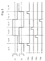
- FIG. 2 shows current and signal profiles in the circuit arrangement according to Fig. 1.
- Fig. 3 serves to explain the distinction between flowing movement and shooting movement.
- Fig. 1 shows a measuring tube 2 with one arranged above Coil 4 and a coil 6 arranged below and two electrodes 8, 10 facing each other Coils 4, 6 are from drivers 12, 14 by one Clock 16 are controlled to generate in the same direction and opposing magnetic fields excitable.
- the drivers 12, 14 are generated by the clock generator 16 via a driver 14 assigned phase shifter 18 controlled such that they Rectangular currents offset by 90 ° in phase are supplied become.
- the output from the electrodes 8, 10 Voltage arrives in a differential amplifier 20, which its output signal holding elements 22a, 22b, 24a, 24b fed. These holding members 22a, 22b, 24a, 24b are controlled by the clock in synchronism with the drivers 12, 14.
- the coils 4 and 6 are fed with currents whose The course depending on the time t can be seen in FIG. 2 are. Overall, the feed is periodic. Each period has four sections, a section -I / -I, in which magnetic fields are generated in the same direction, one Section -I / + I, in which opposing magnetic fields are generated be a section + I / + I, in the opposite direction Magnetic fields are generated and a section + I / -I, in which opposite magnetic fields are generated become. At the end of each section you have stationary states of the magnetic fields set. The then voltages emitted by the electrodes 8, 10 through release signals T22a and T22b, T24a and T24b in the Holding members 22a, 22b, 24a, 24b recorded and stored. The stored signals are at the beginning of a new period deleted.
- a voltage Ur removed that of the voltage between the electrodes 8, 10 in the same direction magnetic fields equivalent.
- a voltage Ug is removed via a subtractor 28, that of the voltage between the electrodes 8, 10 in opposite directions Corresponds to magnetic fields.
- From the tensions Ug and Ur becomes a signal by means of a divider 30 formed, which corresponds to Ug / Ur.
- the tension Ur and that Ug / Ur corresponding signals go to a comparator 32, which makes a distinction according to FIG. 3.
- Within of area 34 Ur and Ug / Ur are related, which corresponds to a flowing movement, i.e. Fr ⁇ 1, in Area 36 in a context that is a shooting Movement, i.e. Fr> 1, corresponds. Whichever of these areas 34, 36 is provided by the comparator 32 a multiplexer 38 into a first or a second Switching state.
- the Ug / Ur corresponding signal also becomes two different ones
- Correction tables 40, 42 supplied of which the correction table 40 is assigned to flowing movement and the correction table 42 is assigned to the shooting movement is.
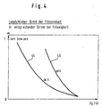
- correction tables 40, 42 accordingly correction factors ⁇ n and ⁇ s, which associated with flowing movement and shooting movement are. 4 shows the dependence of the correction factors ⁇ n and ⁇ s from Ug / Ur.
- the associated ones are visible Curves 44 and 46 differ considerably from one another. With the respective correction factors ⁇ n or
- ⁇ s is multiplied 48 Ur in a multiplier.
- the result is an output signal S which corresponds to the current through the Measuring tube 2 is proportional to whether there is a flowing movement or there is a shooting movement.
Landscapes
- Physics & Mathematics (AREA)
- Fluid Mechanics (AREA)
- General Physics & Mathematics (AREA)
- Electromagnetism (AREA)
- Measurement Of Length, Angles, Or The Like Using Electric Or Magnetic Means (AREA)
- Indicating Or Recording The Presence, Absence, Or Direction Of Movement (AREA)
- Measuring Volume Flow (AREA)
Applications Claiming Priority (2)
| Application Number | Priority Date | Filing Date | Title |
|---|---|---|---|
| DE4330291A DE4330291A1 (de) | 1993-09-07 | 1993-09-07 | Vorrichtung zur Messung des Stroms einer ein Meßrohr durchströmenden Flüssigkeit |
| DE4330291 | 1993-09-07 |
Publications (2)
| Publication Number | Publication Date |
|---|---|
| EP0641999A1 EP0641999A1 (de) | 1995-03-08 |
| EP0641999B1 true EP0641999B1 (de) | 2002-02-27 |
Family
ID=6497083
Family Applications (1)
| Application Number | Title | Priority Date | Filing Date |
|---|---|---|---|
| EP94113964A Expired - Lifetime EP0641999B1 (de) | 1993-09-07 | 1994-09-06 | Vorrichtung zur Messung des Stroms einer ein Messrohr durchströmenden Flüssigkeit |
Country Status (4)
| Country | Link |
|---|---|
| US (1) | US5493914A (da) |
| EP (1) | EP0641999B1 (da) |
| DE (2) | DE4330291A1 (da) |
| DK (1) | DK0641999T3 (da) |
Cited By (1)
| Publication number | Priority date | Publication date | Assignee | Title |
|---|---|---|---|---|
| USRE45447E1 (en) | 2001-07-09 | 2015-04-07 | Endress + Hauser Flowtec Ag | Method of operating an electromagnetic flowmeter |
Families Citing this family (5)
| Publication number | Priority date | Publication date | Assignee | Title |
|---|---|---|---|---|
| EP1275940B1 (de) | 2001-07-09 | 2014-04-09 | Endress + Hauser Flowtec AG | Verfahren zum Betrieb eines magnetischinduktiven Durchflussmessers |
| EP1275941A1 (de) * | 2001-07-09 | 2003-01-15 | Endress + Hauser Flowtec AG | Verfahren zum Betrieb eines magnetisch-induktiven Durchflussmessers |
| DE10356009B4 (de) * | 2003-11-27 | 2007-10-18 | Krohne Meßtechnik GmbH & Co KG | Magnetisch-induktives Durchflußmeßgerät und Verfahren zum Betreiben eines magnetisch-induktiven Durchflußmeßgeräts |
| US7194918B2 (en) * | 2005-08-26 | 2007-03-27 | Krohne Messtechnik Gmbh & Co. Kg | Magnetoinductive flowmeter and method for operating a magnetoinductive flowmeter |
| DE102017105547A1 (de) | 2017-03-15 | 2018-09-20 | Krohne Ag | Verfahren zur Bestimmung des Strömungsprofils, Messwertumformer, magnetisch-induktives Durchflussmessgerät und Verwendung eines magnetisch-induktiven Durchflussmessgeräts |
Family Cites Families (10)
| Publication number | Priority date | Publication date | Assignee | Title |
|---|---|---|---|---|
| US3575051A (en) * | 1968-05-29 | 1971-04-13 | Emerson Electric Co | Magnetic flowmeter |
| US3802262A (en) * | 1971-12-30 | 1974-04-09 | Nasa | Electromagnetic flow rate meter |
| US3981190A (en) * | 1975-05-23 | 1976-09-21 | Sybron Corporation | Electromagnetic flowmeter having internal field coils |
| US4470309A (en) * | 1981-07-06 | 1984-09-11 | Tokyo Shibaura Denki Kabushiki Kaisha | Electromagnetic flowmeter |
| JPS60173024U (ja) * | 1984-04-26 | 1985-11-16 | 株式会社東芝 | 電磁流量計 |
| JPS61155820A (ja) * | 1984-12-28 | 1986-07-15 | Toshiba Corp | 電磁流量計 |
| DE3903068A1 (de) * | 1989-02-02 | 1990-08-16 | Turbo Werk Messtechnik Gmbh | Induktiver durchflussmesser |
| DE59008599D1 (de) * | 1990-04-09 | 1995-04-06 | Fischer & Porter Gmbh | Schaltungsanordnung zur Messung des Stroms einer elektrische Ladungen enthaltenden Flüssigkeit. |
| DK0535257T3 (da) * | 1991-09-10 | 1995-09-11 | Fischer & Porter Gmbh | Indretning til måling af strømningshastigheden af en væske, som strømmer med en fri overflade langs en ledning |
| DE69221595T2 (de) * | 1991-12-18 | 1997-12-11 | Aichi Tokei Denki Kk | Elektromagnetischer Durchflussmesser |
-
1993
- 1993-09-07 DE DE4330291A patent/DE4330291A1/de not_active Ceased
-
1994
- 1994-08-18 US US08/292,283 patent/US5493914A/en not_active Expired - Fee Related
- 1994-09-06 DK DK94113964T patent/DK0641999T3/da active
- 1994-09-06 DE DE59410059T patent/DE59410059D1/de not_active Expired - Fee Related
- 1994-09-06 EP EP94113964A patent/EP0641999B1/de not_active Expired - Lifetime
Cited By (1)
| Publication number | Priority date | Publication date | Assignee | Title |
|---|---|---|---|---|
| USRE45447E1 (en) | 2001-07-09 | 2015-04-07 | Endress + Hauser Flowtec Ag | Method of operating an electromagnetic flowmeter |
Also Published As
| Publication number | Publication date |
|---|---|
| EP0641999A1 (de) | 1995-03-08 |
| DK0641999T3 (da) | 2002-04-22 |
| DE4330291A1 (de) | 1995-03-09 |
| US5493914A (en) | 1996-02-27 |
| DE59410059D1 (de) | 2002-04-04 |
Similar Documents
| Publication | Publication Date | Title |
|---|---|---|
| EP0351451A2 (de) | Schaltungsanordnung zur Regelung eines pulsierenden Stroms | |
| CH634654A5 (de) | Waage mit elektromagnetischer lastkompensation. | |
| DE3633791A1 (de) | Verfahren und anordnung zur messung des widerstandsverhaeltnisses an einer widerstands-halbbruecke | |
| EP0641999B1 (de) | Vorrichtung zur Messung des Stroms einer ein Messrohr durchströmenden Flüssigkeit | |
| DE2133330C3 (de) | Monostabiler Multivibrator | |
| DE1947792A1 (de) | Vier-Quadranten-Impulsbreiten-Multiplikator | |
| DE3525413C2 (da) | ||
| DE3106396A1 (de) | Wandler, insbesondere analog-zu-digital-wandler fuer einen elektromagnetischen stroemungsmesser | |
| DE1288125B (de) | Spannungs-Frequenz-Wandler | |
| EP0641998B1 (de) | Vorrichtung zur Messung des Stroms einer ein Messrohr durchströmenden Flüssigkeit | |
| DE19509815C1 (de) | Schaltung zur Speisung einer Wheatstoneschen Brücke mit einer Rechteckwechselspannung | |
| EP0280261A2 (de) | Schaltung zur Gewinnung eines temperaturunabhängigen Rechtecksignals aus einem Messsignal | |
| DE2727777C3 (de) | Ablenkschaltkreis für eine Kathodenstrahl-Bildröhre | |
| DE2924093A1 (de) | Induktiver differentialweggeber | |
| DE1514342B2 (de) | Ablenkschaltung zur magnetischen ablenkung des kathoden strahls in fernsehtechnischen geraeten mit linearitaets korrektur | |
| EP0464338B1 (de) | Auswerteschaltung für einen induktiven Wegaufnehmer | |
| DE2733792C2 (de) | Verfahren und Schalteinrichtung zur Kompensationsverstärkung periodischer oder getakteter elektrischer Meßsignale | |
| DE2938569C3 (de) | Horizontalablenkschaltung | |
| DE2011367C3 (de) | Schaltungsanordnung fur den elektrisch angetriebenen Schwinger von elektronischen Zeitgebern | |
| DE2302476A1 (de) | Radarablenkgenerator | |
| DD234944A1 (de) | Gleichstrommesseinrichtung mit einem drei wicklungen tragenden magnetkreis | |
| DE955981C (de) | Schaltungsanordnung zur Erzeugung eines saegezahnfoermigen Stromverlaufs | |
| DE2535804C3 (de) | Einrichtung zur Bestimmung der Stärke und der Richtung äußerer Magnetfelder | |
| DE3212942A1 (de) | Stromtreiberschaltung fuer einen elektromechanischen steller | |
| DE1514342C (de) | Ablenkschaltung zur magnetischen Ablenkung des Kathodenstrahls in fernsehtechnischen Geräten mit Linearitätskorrektur |
Legal Events
| Date | Code | Title | Description |
|---|---|---|---|
| PUAI | Public reference made under article 153(3) epc to a published international application that has entered the european phase |
Free format text: ORIGINAL CODE: 0009012 |
|
| AK | Designated contracting states |
Kind code of ref document: A1 Designated state(s): CH DE DK FR GB LI NL |
|
| 17P | Request for examination filed |
Effective date: 19950711 |
|
| GRAG | Despatch of communication of intention to grant |
Free format text: ORIGINAL CODE: EPIDOS AGRA |
|
| 17Q | First examination report despatched |
Effective date: 20010329 |
|
| GRAG | Despatch of communication of intention to grant |
Free format text: ORIGINAL CODE: EPIDOS AGRA |
|
| GRAH | Despatch of communication of intention to grant a patent |
Free format text: ORIGINAL CODE: EPIDOS IGRA |
|
| GRAH | Despatch of communication of intention to grant a patent |
Free format text: ORIGINAL CODE: EPIDOS IGRA |
|
| REG | Reference to a national code |
Ref country code: GB Ref legal event code: IF02 |
|
| GRAA | (expected) grant |
Free format text: ORIGINAL CODE: 0009210 |
|
| AK | Designated contracting states |
Kind code of ref document: B1 Designated state(s): CH DE DK FR GB LI NL |
|
| REG | Reference to a national code |
Ref country code: CH Ref legal event code: EP |
|
| REG | Reference to a national code |
Ref country code: CH Ref legal event code: NV Representative=s name: A. BRAUN, BRAUN, HERITIER, ESCHMANN AG PATENTANWAE |
|
| REF | Corresponds to: |
Ref document number: 59410059 Country of ref document: DE Date of ref document: 20020404 |
|
| GBT | Gb: translation of ep patent filed (gb section 77(6)(a)/1977) |
Effective date: 20020318 |
|
| REG | Reference to a national code |
Ref country code: DK Ref legal event code: T3 |
|
| ET | Fr: translation filed | ||
| PLBE | No opposition filed within time limit |
Free format text: ORIGINAL CODE: 0009261 |
|
| STAA | Information on the status of an ep patent application or granted ep patent |
Free format text: STATUS: NO OPPOSITION FILED WITHIN TIME LIMIT |
|
| 26N | No opposition filed |
Effective date: 20021128 |
|
| PGFP | Annual fee paid to national office [announced via postgrant information from national office to epo] |
Ref country code: FR Payment date: 20050823 Year of fee payment: 12 |
|
| PGFP | Annual fee paid to national office [announced via postgrant information from national office to epo] |
Ref country code: GB Payment date: 20050830 Year of fee payment: 12 |
|
| PGFP | Annual fee paid to national office [announced via postgrant information from national office to epo] |
Ref country code: DE Payment date: 20050912 Year of fee payment: 12 |
|
| PGFP | Annual fee paid to national office [announced via postgrant information from national office to epo] |
Ref country code: NL Payment date: 20050914 Year of fee payment: 12 Ref country code: DK Payment date: 20050914 Year of fee payment: 12 |
|
| PGFP | Annual fee paid to national office [announced via postgrant information from national office to epo] |
Ref country code: CH Payment date: 20050915 Year of fee payment: 12 |
|
| PG25 | Lapsed in a contracting state [announced via postgrant information from national office to epo] |
Ref country code: LI Free format text: LAPSE BECAUSE OF NON-PAYMENT OF DUE FEES Effective date: 20060930 Ref country code: CH Free format text: LAPSE BECAUSE OF NON-PAYMENT OF DUE FEES Effective date: 20060930 |
|
| PG25 | Lapsed in a contracting state [announced via postgrant information from national office to epo] |
Ref country code: DK Free format text: LAPSE BECAUSE OF NON-PAYMENT OF DUE FEES Effective date: 20061002 |
|
| PG25 | Lapsed in a contracting state [announced via postgrant information from national office to epo] |
Ref country code: NL Free format text: LAPSE BECAUSE OF NON-PAYMENT OF DUE FEES Effective date: 20070401 |
|
| PG25 | Lapsed in a contracting state [announced via postgrant information from national office to epo] |
Ref country code: DE Free format text: LAPSE BECAUSE OF NON-PAYMENT OF DUE FEES Effective date: 20070403 |
|
| REG | Reference to a national code |
Ref country code: DK Ref legal event code: EBP |
|
| REG | Reference to a national code |
Ref country code: CH Ref legal event code: PL |
|
| GBPC | Gb: european patent ceased through non-payment of renewal fee |
Effective date: 20060906 |
|
| NLV4 | Nl: lapsed or anulled due to non-payment of the annual fee |
Effective date: 20070401 |
|
| REG | Reference to a national code |
Ref country code: FR Ref legal event code: ST Effective date: 20070531 |
|
| PG25 | Lapsed in a contracting state [announced via postgrant information from national office to epo] |
Ref country code: GB Free format text: LAPSE BECAUSE OF NON-PAYMENT OF DUE FEES Effective date: 20060906 |
|
| PG25 | Lapsed in a contracting state [announced via postgrant information from national office to epo] |
Ref country code: FR Free format text: LAPSE BECAUSE OF NON-PAYMENT OF DUE FEES Effective date: 20061002 |