EP0642009B1 - Verfahren und Apparatur zum Prüfen eines Kühlmittels - Google Patents
Verfahren und Apparatur zum Prüfen eines Kühlmittels Download PDFInfo
- Publication number
- EP0642009B1 EP0642009B1 EP94630050A EP94630050A EP0642009B1 EP 0642009 B1 EP0642009 B1 EP 0642009B1 EP 94630050 A EP94630050 A EP 94630050A EP 94630050 A EP94630050 A EP 94630050A EP 0642009 B1 EP0642009 B1 EP 0642009B1
- Authority
- EP
- European Patent Office
- Prior art keywords
- refrigerant
- indicating
- contaminant
- decomposition
- compound
- Prior art date
- Legal status (The legal status is an assumption and is not a legal conclusion. Google has not performed a legal analysis and makes no representation as to the accuracy of the status listed.)
- Expired - Lifetime
Links
Images


Classifications
-
- G—PHYSICS
- G01—MEASURING; TESTING
- G01N—INVESTIGATING OR ANALYSING MATERIALS BY DETERMINING THEIR CHEMICAL OR PHYSICAL PROPERTIES
- G01N31/00—Investigating or analysing non-biological materials by the use of the chemical methods specified in the subgroup; Apparatus specially adapted for such methods
- G01N31/22—Investigating or analysing non-biological materials by the use of the chemical methods specified in the subgroup; Apparatus specially adapted for such methods using chemical indicators
Definitions
- This invention relates generally to the field of vapor compression air conditioning and refrigeration systems. More specifically, the invention relates to a method, as well as an apparatus for practicing the method, for detecting the presence, as a contaminant, of one type of refrigerant in a system that uses another type of refrigerant.
- CFC chlorofluorocarbon
- CFC and non-CFC based refrigerants In general, one should not mix CFC and non-CFC based refrigerants in the charge of a single system.
- System materials compatible with one refrigerant type are frequently not compatible with another refrigerant type.
- lubricating oils are commonly added to the refrigerant charge in a system to provide lubrication to system components such as the compressor.
- Lubricating oils suitable for use with CFC based refrigerants are not compatible with non-CFC based refrigerants. Use of the improper lubricating oil or charging a system with the incorrect refrigerant can lead to significant, even catastrophic, damage to the system.
- R-12 and R-134a differ in chemical composition, they are both colorless and their saturation temperatures and pressure characteristics are so similar that it is impossible, in a workshop environment, to distinguish between the two using such means as sight or pressure and temperature measurements. Some other method of distinguishing between the two is required.
- the present invention is a method for detecting contamination of a CFC refrigerant by a non-CFC refrigerant or contamination of a non-CFC refrigerant by a CFC refrigerant as well as an apparatus that enables the practice of the method with a device that is compact, easy to use and inexpensive to make and operate.
- a CFC refrigerant such as R-12 will decompose, producing decomposition products. There may be secondary chemical reactions leading to further decomposition products. The presence of one or more of these decomposition products can be indicated by a suitable indicator.
- the reaction conditions that cause the CFC refrigerant to decompose have no effect on non-CFC refrigerants such as R-134a.
- a non-CFC refrigerant such as R-134a will decompose, producing hydrofluoric and/or trifluoracetic acid as decomposition products.
- the presence of an acid can also be indicated by a suitable indicator.
- the reaction conditions that cause the non-CFC refrigerant to decompose have no effect on CFC refrigerants such as R-12.
- the apparatus of the present invention uses the above principles in a compact, portable and inexpensive package that includes a decomposition chamber in flow communication both with a source of refrigerant to be tested and with an indicator chamber having a suitable indicator.
- a technician suspects that a system containing a CFC refrigerant is contaminated with a non-CFC refrigerant or that a system containing a non-CFC refrigerant is contaminated with a CFC refrigerant, he can connect a suitable embodiment of the apparatus to a charging connection in the system.
- System refrigerant then flows into the apparatus decomposition chamber where the suspected contaminant, if any, is decomposed into other chemical compounds, primarily acids.
- the decomposed refrigerant products flow from the decomposition chamber to an indicator chamber where it passes through a suitable indicator.
- the indicator will detect the presence of the decomposition product in the refrigerant and provide a display. A positive indication shows that there is contaminant refrigerant in the refrigeration system tested.
- FIG. 1 is a schematic diagram that illustrates the principles underlying the apparatus of the present invention.
- FIGS. 2A, 2B, and 2C are schematic diagrams of different embodiments of the apparatus of the present invention.
- FIG. 3 is an elevation view of one embodiment of the apparatus of the present invention.
- Refrigerant R-12 may be decomposed in at least three ways useful in the present invention:
- the direct or secondary decomposition products resulting, for example, from hydrolysis can be detected by a suitable acid indicator.
- Refrigerant R-12 does not react with hydroxyl radicals.
- Refrigerant R-134a does react with OH to produce tetrafluoroethyl radicals and water as shown in the equation CF 3 CH 2 F + OH ⁇ CF 3 CHF + H 2 O.
- the CF 3 CH 2 radical reacts further to produce trifluoroacetic acid and hydrofluoric acid, as shown in the equation CF 3 CHF + OH, H 2 O ⁇ CF 3 C(O)OH, HF, F - , H 3 O + , other products.
- the decomposition products can be detected by a suitable acid indicator.
- the above principles allow one to determine the presence of a contaminating refrigerant of one type in a refrigerant of another type both when the contaminant is a CFC refrigerant in a non-CFC refrigerant and when the contaminant is a non-CFC refrigerant in a CFC refrigerant.
- a source of supply of the refrigerant such as an air conditioning or refrigeration system or a replenishment cylinder.
- the sample is then exposed to a reagent that, under conditions appropriate to the refrigerant and the reagent, will cause the decomposition of the suspected contaminant.
- the sample is then tested for the presence of a telltale product of decomposition. If the test shows the presence of the product of decomposition, then one can conclude that the source of refrigerant is contaminated by refrigerant of a non-compatible type.
- FIG. 1 depicts schematically an apparatus that embodies the teachings of the present invention.
- the figure shows testing apparatus 10 in position to be attached to refrigerant source 91.
- Fitting 12 connects apparatus 10 to source 91.
- refrigerant flows from source 91 through flow limiting device 11 into decomposition chamber 21.
- Reagent 22 is located in chamber 21.
- Reagent 22 is chosen so as to be nonreactive with refrigerant that is proper for the source being tested but to decompose refrigerant of the improper type.
- refrigerant flowing into indicator chamber 31 may contain a product of the decomposition of a contaminating refrigerant if source 91 is contaminated.
- Indicator 32 is located in chamber 31. Indicator 32 may be of any suitable type that will detect and indicate the presence of a decomposition product of the contaminating refrigerant.
- a colorimetric indicator is simple and convenient for this use.
- Such an indicator comprises a bed of a substance through or over which a fluid to be tested may flow.
- the substance is chosen so that it will react with the component of the fluid it is desired to detect to produce a change in color in the bed.
- a color change in the bed is indicative of the presence of the refrigerant decomposition product. It must, of course, be possible to observe the indicator bed to determine a change in color. This can be accomplished by making indicator 32 so that it can be removed from chamber 31 for reading, providing a window in a wall of chamber 31 or simply making the wall of the chamber transparent.
- the refrigerant flows into collector 41 where the refrigerant effluent is stored for disposal.
- FIGS. 2A, 2B, and 2C more specifically depict schematically different embodiments of the testing apparatus of the present invention that take advantage of the various phenomena discussed above to detect refrigerant contamination.
- features that are unique to a particular embodiment have reference identifiers with letter suffixes that correspond to the letter suffix of the figure identifier.
- Features that are the same as corresponding features in FIG. 1 have reference identifiers without letter suffixes.
- FIG. 2A s hows testing apparatus 10A for the detection of refrigerant R-12 as a contaminant in refrigerant R-134a.
- the reagent in this embodiment is ultraviolet lamp 22A, which receives its power from power supply 23 .
- Indicator 32A in indicator chamber 31 therefore is of a type that will detect the presence of acids and preferably is a colorimetric indicator.
- FIG. 2B shows another testing apparatus, 10B, for the detection of refrigerant R-12 as a contaminant in refrigerant R-134a.
- the reagent in this embodiment is heat provided by heating element 22B, located in decomposition chamber 21 and powered by power supply 23. Under properly elevated temperatures, R-12 decomposes as discussed above.
- Indicator 32B in chamber 31 therefore is of a type that will detect the presence of acids and preferably is a colorimetric indicator.
- FIG. 2C shows testing apparatus 10C for the detection of refrigerant R-134a as a contaminant in refrigerant R-12.
- decomposition chamber 22 which chamber also contains a source of hydroxyl radicals such as hydrogen peroxide.
- Element 25C is a gas effusion device for saturating the source of OH radicals with the refrigerant.
- lamp 22A and lamp 22C may be identical with the exception of fitting lamp 22C with a filter that allows only ultraviolet light of the desired wavelength to pass.
- acids are secondary decomposition products of R-134a.
- Indicator 32C in chamber 31 is therefore of a type that will detect the presence of acids and preferably is a colorimetric indicator.
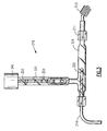
- FIG. 3 is an elevation view of an apparatus for testing for refrigerant R-12 contamination in refrigerant R-134a that embodies the teaching of the present invention.
- Refrigerant flows into apparatus 310 through connector 312, a Schrader® fitting of the type that will mate with the Schrader® charging valve found on nearly all air conditioning and refrigeration systems.
- Coupling 311 contains an orifice as a flow limiting device.
- Power cord 314 supplies power to lamp 322 from a power supply (not illustrated).
- Inside indicator chamber 331 is indicator tube 332 that contains colorimetric indicating medium 333.
- Collector 341 collects refrigerant that passes through apparatus 310 for later disposal.
- indicator chamber 331 The wall of indicator chamber 331 is made of a transparent material such as plastic.
- Indicator tube 332 is made of transparent glass or plastic. Indicating medium 333 is therefore visible through chamber 331 and tube 332.
- Indicator tube 332 can be the same or similar to the tube described in U.S. Patent 4,923,806, issued 8 May 1990 to Klowdowski and assigned to the same assignee as the present invention.
- the '806 patent covers the TOTALTEST® refrigerant testing device now in widespread use.
- the tube of the '806 patent and used in the TOTALTEST® device contains two colorimetric indicators, one that indicates the presence of water in a refrigerant sample and one that indicates the presence of acid.
- the acid indicating medium in the '806 tube is bromophenol blue on a glycerol film coating a silica sand base. The medium is initially blue in color. In contact with acid, the medium turns a purple or purplish pink color.
- the apparatus of the present invention does not use the moisture detecting capability of the '806 tube but the presence of the moisture indicating medium does not adversely impact on the tube's use in the apparatus.
- indicator tube 322 could be specially made for use in the apparatus of the present invention and have, as illustrated in FIG. 3, only a single bed of indicating medium.
- the tube ends are heated and drawn to a close to seal the indicating media from exposure to air.
- the test operator To test a sample of refrigerant R-134a for contamination by refrigerant R-12 using apparatus 310 and an indicating tube having a bromophenol blue indicating medium, the test operator first breaks the ends off indicator tube 322 and inserts the tube into indicator chamber 331. Then the operator connects apparatus 310 to a source of the refrigerant to be tested by means of connector 312 and energizes lamp 322. With apparatus 310 connected to the refrigerant source, a sample of refrigerant flows from the source through connector 312 and coupling 311 into decomposition chamber 321. There, refrigerant R-12 present in the sample will decompose when exposed to ultraviolet light from lamp 322.
- the refrigerant sample then enters indicating chamber 331 and flows through indicator tube 332, where it passes through and contacts indicating medium 333. If there is refrigerant R-12 in the sample flow, the acidic decomposition products of that refrigerant will react with indicating medium 333 to produce a color change in the medium.
- Apparatus 310 can be quickly and easily converted to test refrigerant R-12 for contamination by refrigerant R-134a by either replacing lamp 322 with a lamp that emits ultraviolet light of the proper wavelength or installing a filter on the existing lamp and by providing a source of hydroxyl ions in decomposition chamber 321.
- acid can be present in a refrigerant from several sources, primarily the decomposed insulation of an overheated compressor motor. If an acid indicating medium is used to detect the presence of refrigerant decomposition products, acid from other sources could produce a false positive indication of contamination. Therefore, before conducting a test for contamination of one refrigerant type by another refrigerant type, one should first determine that the refrigerant to be tested is free of acid.
- the TOTALTEST® device can be used for that determination or apparatus 310 can be used with lamp 322 deenergized to prevent refrigerant decomposition.
Landscapes
- Life Sciences & Earth Sciences (AREA)
- Health & Medical Sciences (AREA)
- Analytical Chemistry (AREA)
- Molecular Biology (AREA)
- Physics & Mathematics (AREA)
- Chemical & Material Sciences (AREA)
- Biophysics (AREA)
- Biochemistry (AREA)
- General Health & Medical Sciences (AREA)
- General Physics & Mathematics (AREA)
- Immunology (AREA)
- Pathology (AREA)
- Investigating Or Analyzing Non-Biological Materials By The Use Of Chemical Means (AREA)
- Testing Resistance To Weather, Investigating Materials By Mechanical Methods (AREA)
- Sampling And Sample Adjustment (AREA)
Claims (20)
- Verfahren zur Prüfung eines Kältemittels, welche eine nicht verunreinigte erste Kältemittelverbindung sein sollte, auf Verunreinigung durch eine zweite Kältemittelverbindung, umfassend die Schritte:Entnehmen einer Kältemittelfließprobe aus einem geschlossenen, ein Kältemittel enthaltenden System;Kontaktieren der Kältemittelfließprobe mit Mitteln zur Zersetzung der zweiten Kältemittelverbindung; undPrüfung der Fließprobe durch kontaktieren der Fließprobe mit Mitteln zur Anzeige einer Präsenz eines Zersetzungsproduktes der zweiten Kältemittelverbindung, wobei eine positive Anzeige für die Präsenz des Zersetzungsproduktes ein Anzeichen einer Kontamination des Kältemittels durch die zweite Kältemittelverbindung darstellt.
- Verfahren nach Anspruch 1, umfassend den Schritt:der nach der Entnahme und vor dem Kontaktieren durchgeführt wird.Druckreduzierung der Fließprobe,
- Prüfvorrichtung (10) zur Prüfung eines Kältemittels, das eine reine, erste Kältemittelverbindung sein sollte, auf die Verunreinigung durch eine zweite Kältemittelverbindung, umfassend:Entnahmemittel (12) zur Entnahme einer Kältemittelfließprobe aus einem geschlossenen System (91), welches ein Kältemittel enthält,den Entnahmemitteln stromabwärts nachgeschaltete Mittel (21) zum Kontaktieren der Fließprobe mit Zersetzungsmitteln (22, 25c) zur Zersetzung der zweiten Kältemittelverbindung; undIndikatormittel (31, 32), den Mitteln zum Kontaktieren stromabwärts nachgeschaltet, zur Präsenzanzeige eines Zersetzungsproduktes der zweiten Kältemittelverbindung, wobei eine positive Anzeige der Präsenz des zerlegten Produktes ein Indiz für die Kontaminierung des Kältemittels durch die zweite Kältemittelverbindung darstellt.
- Vorrichtung nach Anspruch 3, umfassend:Mittel (11), den Entnahmemitteln stromabwärts nachgeschaltete und stromaufwärts zu den Kontaktierungsmitteln, um den Druck der Fließprobe zu reduzieren.
- Vorrichtung nach Anspruch 3, wobei das Druckreduzierungsmittel eine Drosselblende (orifice) umfasst.
- Vorrichtung nach Anspruch 3, umfassend:Sammlungsmittel (41), den Prüfungsmitteln stromabwärts nachgeschaltet, zum Sammeln der Fließprobe.
- Vorrichtung nach Anspruch 3, wobei die Entnahmemittel umfassen:eine Armatur (312), angepasst zur Verbindung an eine Prüf/ Füllarmatur in dem geschlossenen System.
- Vorrichtung nach Anspruch 3, wobei das verursachende Mittel eine Zersetzungsreaktionskammer (32) umfasst.
- Vorrichtung nach Anspruch 3, wobei das Zersetzungsmitteln eine UV-Lampe (22A) umfasst.
- Vorrichtung nach Anspruch 9, wobei die Lampe ultraviolette Energie mit einer Wellenlänge von 184,9 nm emittiert.
- Vorrichtung nach Anspruch 9, wobei das Zersetzungsmittel umfasst:eine UV-Lampe (22C), die ultraviolette Energie mit einer Wellenlänge von 254 nm emittiert, undMittel (25C) zur Erzeugung von Hydroxyl-Ionen.
- Vorrichtung nach Anspruch 3, wobei das Indikatormittel eine Quarz-Sand-Basis beschichtet mit Bromphenol Blau in einem Glycerol- Film umfasst.
- Vorrichtung nach Anspruch 3, wobei das Indikatormittel umfasst:ein transparentes Rohr mit einer darin angeordneten, eine Kontaminierung anzeigende Substanz, geeignet um die Präsenz eines Kältemittel-Zersetzungsprodukts anzuzeigen.
- Vorrichtung nach Anspruch 13, wobei die Kontaminations-Indikator-Substanz, umfasst:eine Quarz-Sand-Basis beschichtet mit Bromphenol Blau in einem Glycerol- Film.
- Vorrichtung zur Prüfung eines Kältemittels, welches reines Kältemittel R-134a sein sollte, auf die kontaminierende Präsenz eines R-12 Kältemittels, umfassend:Verbindungsmittel (312) zur Verbindung der Vorrichtung zu der Quelle des zu prüfenden Kältemittels;Mittel (311), nachgeschaltet stromabwärts den Verbindungsmitteln, zur Druckreduzierung des Kältemittels;eine Zersetzungsreaktionskammer (321) stromabwärts nachgeschaltet dem Druckreduzierungsmittel;eine Lampe, geeignet ultraviolette Energie mit einer Wellenlänge von 184,9 nm zu emittieren, und angeordnet in der Zersetzungsreaktionskammer;eine Kontaminations-Indikator-Halterung-Anordnung (331) stromabwärts nachgeschaltet der Zersetzungsreaktionskammer.
- Vorrichtung nach Anspruch 15, umfassend:ein transparentes Rohr (332) mit darin angeordneter Kontaminations-Indikator-Substanz (333), geeignet um die Präsenz eines Kältemittel-Zersetzungsprodukts anzuzeigen.
- Vorrichtung nach Anspruch 15, wobei die Kontaminations-Indikator-Substanz umfasst:eine Quarz-Sand-Basis beschichtet mit Bromphenol Blau in einem Glycerol- Film.
- Vorrichtung zur Prüfung eines Kältemittels, das reines R-12 Kältemittel sein sollte, auf die kontaminierende Präsenz eines R-134a Kältemittels, umfassend:Verbindungsmittel (12) zur Verbindung der Vorrichtung mit der Quelle des zu prüfenden Kältemittels;Mittel (11), stromabwärts nachgeschaltet dem Verbindungsmittel zur Druckreduzierung des Kältemittels;eine Zersetzungsreaktionskammer (21) stromabwärts nachgeschaltete dem Druckreduzierungsmittel;eine Lampe (22C), geeignet zum emittieren ultravioletter Energie mit einer Wellenlänge von 254 nm, die in'der Zersetzungsreaktionskammer angeordnete ist;Mittel (25C) zur Erzeugung von Hydroxyl-Ionen, angeordnet in der Zersetzungsreaktionskammer; undeine Kontaminations-Indikator-Halterungs-Anordnung (31) stromabwärts nachgeschaltet der Zersetzungsreaktionskammer.
- Vorrichtung nach Anspruch 18, umfassend:ein transparentes Rohr (332) mit einer darin angeordneten Kontaminations-Indikator-Substanz (333), geeignet um die Präsenz eines Kältemittel-Zersetzungsprodukts anzuzeigen.
- Vorrichtung nach Anspruch 19, wobei die Kontaminations-Indikator-Substanz umfasst:eine Quarz-Sand-Basis beschichtet mit Bromphenol Blau in einem Glycerol- Film.
Applications Claiming Priority (2)
| Application Number | Priority Date | Filing Date | Title |
|---|---|---|---|
| US08/116,936 US5363661A (en) | 1993-09-03 | 1993-09-03 | Method and apparatus for testing refrigerant |
| US116936 | 1993-09-03 |
Publications (3)
| Publication Number | Publication Date |
|---|---|
| EP0642009A2 EP0642009A2 (de) | 1995-03-08 |
| EP0642009A3 EP0642009A3 (de) | 1995-12-27 |
| EP0642009B1 true EP0642009B1 (de) | 2002-12-18 |
Family
ID=22370145
Family Applications (1)
| Application Number | Title | Priority Date | Filing Date |
|---|---|---|---|
| EP94630050A Expired - Lifetime EP0642009B1 (de) | 1993-09-03 | 1994-09-01 | Verfahren und Apparatur zum Prüfen eines Kühlmittels |
Country Status (9)
| Country | Link |
|---|---|
| US (1) | US5363661A (de) |
| EP (1) | EP0642009B1 (de) |
| JP (1) | JP2513446B2 (de) |
| AU (1) | AU671381B2 (de) |
| BR (1) | BR9403405A (de) |
| CA (1) | CA2129561C (de) |
| CO (1) | CO4180483A1 (de) |
| DE (1) | DE69431897T2 (de) |
| NZ (1) | NZ264150A (de) |
Families Citing this family (16)
| Publication number | Priority date | Publication date | Assignee | Title |
|---|---|---|---|---|
| US6514765B1 (en) * | 1995-04-17 | 2003-02-04 | Mainstream Engineering Corporation | Acid test kit and method of use |
| US5846833A (en) * | 1997-01-17 | 1998-12-08 | Carrier Corporation | Method and apparatus for testing a non-hydrocarbon refrigerant |
| BR9700384A (pt) * | 1997-03-12 | 1998-12-08 | Brasil Compressores Sa | Sistema e método para detecção de anticongelantes em compressor hermético |
| GB2324868B (en) * | 1997-05-01 | 2001-11-21 | Sun Electric Uk Ltd | Method and apparatus for matching refrigerants |
| WO1999047916A1 (en) * | 1998-03-17 | 1999-09-23 | Johnson James R | Method and apparatus for testing surfaces |
| US6035648A (en) * | 1998-08-03 | 2000-03-14 | York International Corporation | Method of charging and recharging a refrigeration system containing a ternary refrigerant |
| US6576473B1 (en) * | 1999-05-28 | 2003-06-10 | Mainstream Engineering Corporation | Removable test kit and method of use for vapor compression systems |
| NL1025042C2 (nl) * | 2003-12-17 | 2005-06-20 | Sgt Singapore Holding Pte Ltd | Regulator voorzien van een indicatoreenheid alsmede een kit van onderdelen omvattende een indicatoreenheid ten behoeve van een dergelijke regulator en een gasbron. |
| WO2007123544A1 (en) * | 2006-04-25 | 2007-11-01 | Carrier Corporation | System performance correction by modifying refrigerant composition in a refrigerant system |
| JP5800562B2 (ja) * | 2011-05-10 | 2015-10-28 | 三菱電機株式会社 | 冷凍空調機の不良原因推定方法 |
| US9733229B1 (en) * | 2013-03-15 | 2017-08-15 | Zynon Technologies, Llc | Test kit for detecting acids in refrigerant lubricating oils and method of use |
| SG11201706202VA (en) * | 2015-02-02 | 2017-08-30 | Carrier Corp | Refrigerant analyzer and a method of using the same |
| CN108139348B (zh) | 2015-07-28 | 2021-09-17 | 开利公司 | 制冷剂分析仪及其使用方法 |
| DE202017105769U1 (de) | 2016-09-23 | 2017-12-21 | Trane International Inc. | System zum Detektieren einer Verunreinigung von Kältemittelgas in einem HLKK-System |
| KR102872441B1 (ko) * | 2023-11-07 | 2025-10-23 | 한국표준과학연구원 | 혼합 냉매 열전도도 측정 시스템 및 이의 운전 방법 |
| DE102023136051B3 (de) | 2023-12-20 | 2025-03-20 | Audi Aktiengesellschaft | Kältemittelkreis mit einem Kältemittelsubstitut, Kraftfahrzeug und Verfahren zum Betreiben des Kältemittelkreises |
Family Cites Families (9)
| Publication number | Priority date | Publication date | Assignee | Title |
|---|---|---|---|---|
| US4923806A (en) * | 1985-06-14 | 1990-05-08 | Carrier Corporation | Method and apparatus for refrigerant testing in a closed system |
| US5071768A (en) * | 1985-06-14 | 1991-12-10 | Carrier Corporation | Method and apparatus for refrigerant testing in a closed system |
| US4803843A (en) * | 1988-02-12 | 1989-02-14 | Carrier Corporation | Low pressure refrigerant contaminant tester |
| US5186899A (en) * | 1990-11-13 | 1993-02-16 | Drago Thomas E | Fixture for supporting a refrigerant sampling tube in a closed system |
| US5158747A (en) * | 1991-04-26 | 1992-10-27 | Spx Corporation | Apparatus for identifying and distinguishing different refrigerants |
| US5237873A (en) * | 1991-09-18 | 1993-08-24 | Dennis Eichenlaub | Method of determining type of refrigerant |
| US5214931A (en) * | 1991-12-20 | 1993-06-01 | Carrier Corporation | Apparatus for sampling the purity of refrigerant in the storage container of a refrigerant recovery and purification system |
| US5255527A (en) * | 1992-01-02 | 1993-10-26 | Carrier Corporation | Method of testing the purity of refrigerant flowing through a refrigeration system |
| US5295360A (en) * | 1993-04-12 | 1994-03-22 | Spx Corporation | Apparatus for identifying and distinguishing different refrigerants |
-
1993
- 1993-09-03 US US08/116,936 patent/US5363661A/en not_active Expired - Lifetime
-
1994
- 1994-08-02 NZ NZ264150A patent/NZ264150A/en not_active IP Right Cessation
- 1994-08-05 CA CA002129561A patent/CA2129561C/en not_active Expired - Fee Related
- 1994-08-23 JP JP6197107A patent/JP2513446B2/ja not_active Expired - Fee Related
- 1994-08-31 BR BR9403405A patent/BR9403405A/pt not_active IP Right Cessation
- 1994-08-31 CO CO94038862A patent/CO4180483A1/es unknown
- 1994-09-01 DE DE69431897T patent/DE69431897T2/de not_active Expired - Fee Related
- 1994-09-01 EP EP94630050A patent/EP0642009B1/de not_active Expired - Lifetime
- 1994-09-01 AU AU71634/94A patent/AU671381B2/en not_active Ceased
Also Published As
| Publication number | Publication date |
|---|---|
| CA2129561A1 (en) | 1995-03-04 |
| BR9403405A (pt) | 1995-05-09 |
| EP0642009A2 (de) | 1995-03-08 |
| EP0642009A3 (de) | 1995-12-27 |
| NZ264150A (en) | 1996-07-26 |
| AU7163494A (en) | 1995-03-16 |
| DE69431897D1 (de) | 2003-01-30 |
| JP2513446B2 (ja) | 1996-07-03 |
| DE69431897T2 (de) | 2003-08-21 |
| JPH07209277A (ja) | 1995-08-11 |
| CO4180483A1 (es) | 1995-06-07 |
| AU671381B2 (en) | 1996-08-22 |
| US5363661A (en) | 1994-11-15 |
| CA2129561C (en) | 2002-02-26 |
Similar Documents
| Publication | Publication Date | Title |
|---|---|---|
| EP0642009B1 (de) | Verfahren und Apparatur zum Prüfen eines Kühlmittels | |
| US5371019A (en) | Method and apparatus for analyzing refrigerant properties | |
| US5295360A (en) | Apparatus for identifying and distinguishing different refrigerants | |
| US5597533A (en) | Apparatus for analyzing refrigerant properties | |
| Minor et al. | HFO-1234yf low GWP refrigerant update | |
| US11927354B2 (en) | Method and system for flammable gas detection | |
| JP3029210B2 (ja) | 冷媒中の汚染物の試験装置 | |
| JPS63255658A (ja) | 閉鎖系装置の冷媒を試験するための方法及び装置 | |
| KR0138497B1 (ko) | 소형 가스 감지기 | |
| US4803843A (en) | Low pressure refrigerant contaminant tester | |
| US20140151242A1 (en) | Leak detection formula, analyzer and methods of use | |
| US6514765B1 (en) | Acid test kit and method of use | |
| US5846833A (en) | Method and apparatus for testing a non-hydrocarbon refrigerant | |
| US6018983A (en) | Method and apparatus for matching refrigerants | |
| KR870000260B1 (ko) | 가스 누설 검지 소자 | |
| KR100432406B1 (ko) | 진단형 디젤 광투과식 매연측정기 | |
| EP2951571B1 (de) | Leckdetektionsformel, analysevorrichtung und verfahren | |
| US11959831B1 (en) | Leak detection formula, analyze and methods of use | |
| JP2562433Y2 (ja) | 冷媒状態検出装置 | |
| JPH06323944A (ja) | 気密検査方法及びその装置 | |
| US20190234923A1 (en) | Heat-sealable chemical vapor-sensor bag |
Legal Events
| Date | Code | Title | Description |
|---|---|---|---|
| PUAI | Public reference made under article 153(3) epc to a published international application that has entered the european phase |
Free format text: ORIGINAL CODE: 0009012 |
|
| AK | Designated contracting states |
Kind code of ref document: A2 Designated state(s): CH DE ES FR GB IT LI |
|
| PUAL | Search report despatched |
Free format text: ORIGINAL CODE: 0009013 |
|
| AK | Designated contracting states |
Kind code of ref document: A3 Designated state(s): CH DE ES FR GB IT LI |
|
| 17P | Request for examination filed |
Effective date: 19960610 |
|
| GRAG | Despatch of communication of intention to grant |
Free format text: ORIGINAL CODE: EPIDOS AGRA |
|
| 17Q | First examination report despatched |
Effective date: 20020207 |
|
| GRAG | Despatch of communication of intention to grant |
Free format text: ORIGINAL CODE: EPIDOS AGRA |
|
| GRAH | Despatch of communication of intention to grant a patent |
Free format text: ORIGINAL CODE: EPIDOS IGRA |
|
| GRAH | Despatch of communication of intention to grant a patent |
Free format text: ORIGINAL CODE: EPIDOS IGRA |
|
| GRAA | (expected) grant |
Free format text: ORIGINAL CODE: 0009210 |
|
| AK | Designated contracting states |
Kind code of ref document: B1 Designated state(s): CH DE ES FR GB IT LI |
|
| PG25 | Lapsed in a contracting state [announced via postgrant information from national office to epo] |
Ref country code: LI Free format text: LAPSE BECAUSE OF FAILURE TO SUBMIT A TRANSLATION OF THE DESCRIPTION OR TO PAY THE FEE WITHIN THE PRESCRIBED TIME-LIMIT Effective date: 20021218 Ref country code: IT Free format text: LAPSE BECAUSE OF FAILURE TO SUBMIT A TRANSLATION OF THE DESCRIPTION OR TO PAY THE FEE WITHIN THE PRE;WARNING: LAPSES OF ITALIAN PATENTS WITH EFFECTIVE DATE BEFORE 2007 MAY HAVE OCCURRED AT ANY TIME BEFORE 2007. THE CORRECT EFFECTIVE DATE MAY BE DIFFERENT FROM THE ONE RECORDED.SCRIBED TIME-LIMIT Effective date: 20021218 Ref country code: CH Free format text: LAPSE BECAUSE OF FAILURE TO SUBMIT A TRANSLATION OF THE DESCRIPTION OR TO PAY THE FEE WITHIN THE PRESCRIBED TIME-LIMIT Effective date: 20021218 |
|
| REG | Reference to a national code |
Ref country code: GB Ref legal event code: FG4D |
|
| REG | Reference to a national code |
Ref country code: CH Ref legal event code: EP |
|
| REF | Corresponds to: |
Ref document number: 69431897 Country of ref document: DE Date of ref document: 20030130 Kind code of ref document: P Ref document number: 69431897 Country of ref document: DE Date of ref document: 20030130 |
|
| ET | Fr: translation filed | ||
| PG25 | Lapsed in a contracting state [announced via postgrant information from national office to epo] |
Ref country code: ES Free format text: LAPSE BECAUSE OF FAILURE TO SUBMIT A TRANSLATION OF THE DESCRIPTION OR TO PAY THE FEE WITHIN THE PRESCRIBED TIME-LIMIT Effective date: 20030627 |
|
| REG | Reference to a national code |
Ref country code: CH Ref legal event code: PL |
|
| PLBE | No opposition filed within time limit |
Free format text: ORIGINAL CODE: 0009261 |
|
| STAA | Information on the status of an ep patent application or granted ep patent |
Free format text: STATUS: NO OPPOSITION FILED WITHIN TIME LIMIT |
|
| 26N | No opposition filed |
Effective date: 20030919 |
|
| PGFP | Annual fee paid to national office [announced via postgrant information from national office to epo] |
Ref country code: FR Payment date: 20080904 Year of fee payment: 15 |
|
| PGFP | Annual fee paid to national office [announced via postgrant information from national office to epo] |
Ref country code: GB Payment date: 20080808 Year of fee payment: 15 |
|
| PGFP | Annual fee paid to national office [announced via postgrant information from national office to epo] |
Ref country code: DE Payment date: 20080930 Year of fee payment: 15 |
|
| GBPC | Gb: european patent ceased through non-payment of renewal fee |
Effective date: 20090901 |
|
| REG | Reference to a national code |
Ref country code: FR Ref legal event code: ST Effective date: 20100531 |
|
| PG25 | Lapsed in a contracting state [announced via postgrant information from national office to epo] |
Ref country code: FR Free format text: LAPSE BECAUSE OF NON-PAYMENT OF DUE FEES Effective date: 20090930 Ref country code: DE Free format text: LAPSE BECAUSE OF NON-PAYMENT OF DUE FEES Effective date: 20100401 |
|
| PG25 | Lapsed in a contracting state [announced via postgrant information from national office to epo] |
Ref country code: GB Free format text: LAPSE BECAUSE OF NON-PAYMENT OF DUE FEES Effective date: 20090901 |