EP0642849B2 - Verwendung von stark entwässerten, ggf. kontaminierten Sedimenten und/oder davon abgetrennten, ggf. kontaminierten Feinsedimenten in Form von Bauelementen zur subaquatischen Auffüllung von trockenzulegenden Gewässern, insbesondere Hafenbecken - Google Patents
Verwendung von stark entwässerten, ggf. kontaminierten Sedimenten und/oder davon abgetrennten, ggf. kontaminierten Feinsedimenten in Form von Bauelementen zur subaquatischen Auffüllung von trockenzulegenden Gewässern, insbesondere Hafenbecken Download PDFInfo
- Publication number
- EP0642849B2 EP0642849B2 EP94113112A EP94113112A EP0642849B2 EP 0642849 B2 EP0642849 B2 EP 0642849B2 EP 94113112 A EP94113112 A EP 94113112A EP 94113112 A EP94113112 A EP 94113112A EP 0642849 B2 EP0642849 B2 EP 0642849B2
- Authority
- EP
- European Patent Office
- Prior art keywords
- water
- sediment
- contaminated
- silt
- packaging wrapping
- Prior art date
- Legal status (The legal status is an assumption and is not a legal conclusion. Google has not performed a legal analysis and makes no representation as to the accuracy of the status listed.)
- Expired - Lifetime
Links
Images


Classifications
-
- E—FIXED CONSTRUCTIONS
- E02—HYDRAULIC ENGINEERING; FOUNDATIONS; SOIL SHIFTING
- E02D—FOUNDATIONS; EXCAVATIONS; EMBANKMENTS; UNDERGROUND OR UNDERWATER STRUCTURES
- E02D15/00—Handling building or like materials for hydraulic engineering or foundations
- E02D15/08—Sinking workpieces into water or soil inasmuch as not provided for elsewhere
-
- B—PERFORMING OPERATIONS; TRANSPORTING
- B09—DISPOSAL OF SOLID WASTE; RECLAMATION OF CONTAMINATED SOIL
- B09B—DISPOSAL OF SOLID WASTE NOT OTHERWISE PROVIDED FOR
- B09B1/00—Dumping solid waste
- B09B1/002—Sea dumping
Definitions
- the present invention relates to the use of highly drained, optionally contaminated sediments and / or thereof separated, possibly contaminated fine sediments in Form of components for subaquatic filling of dry materials Waters, especially docks.
- the dredged harbor sediment (dredged material) is being Barges delivered and initially freed from coarse foreign matter.
- the fine-grained sediment obtained after the coarse grain separation is then fed to a two-stage separation plant, in which carried out hydro-classification and up-stream sorting becomes.
- the Fine sediments Smaller than 63 m ⁇
- the second Separation stage i.e. the upstream sorting.
- the one out Sorted clean sand is removed with the help of a drainage sieve dewatered to approx. 85% dry matter and out the system for further use as building material on conveyor belts carried out.
- the fine sludge suspension which for reasons of efficient Separation contains a very high proportion of water, initially with the addition of flocculants to higher solids contents thickened and finally by means of a belt press and a high pressure post-drainage press to a silt cake dewatered, which then on a landfill site in the form of a Mud hill is deposited.
- the landfill currently stands for this Frankopp available, which sealed like a normal landfill is.
- the stability of the deposited silt cake which is inherently poor soil mechanics Properties and therefore only low stability, even at the drainage level achieved in METHA III, having.
- other landfill areas only in are very limited and landfill operations is very expensive since the landfills are practical for everyone to come Times need to be monitored and maintained.
- Another Possibility of disposal of the dredged material itself or the separated one contaminated port silt would be desirable. The the same applies, for example, to dredged material from rivers and sedimented industrial and sewage sludge.
- the present invention has the task to find a way that allows dredged material or Port silt, especially in contaminated form, as well sedated industrial and sewage sludge for filling small harbor basins or other bodies of water.
- this object is achieved by that you drained to a large extent, if necessary contaminated sediments, for example those that accumulate as dredged material Port sediments and / or the separated ones, if necessary contaminated port silt, under pressure, preferably with further dewatering, pressed into a shaped body, this with a deformable, water-permeable packaging sleeve surrounds on all sides and the component thus obtained for subaquatic Replenishment of docks or other bodies of water used.
- the present invention thus relates to the use from largely dewatered by pressing, possibly contaminated Sediments and / or fine sediments separated from them in the form of components, which consist of pressed moldings by a Packaging envelope are surrounded, for subaquatic filling of dry matter Waters, especially docks.
- the sediments which can be used according to the invention preferably include Deposits in natural or artificial waters, e.g. Dredged material from ports and rivers as well as the where appropriate fine sediments separated from it (silt) and sedimented Industrial and sewage sludge.
- the industrial sludges include also fly ash in slurried form.
- components to be used consist according to the present invention of a highly compressed by compression, highly drained, homogeneous moldings Sediment, especially from dredged material and / or separated from it Port silt, which on all sides with a deformable, water-permeable Packaging envelope is surrounded.
- the packaging envelope preferably consists of textiles, e.g. a nonwoven.
- the packaging sleeve made of nonwoven as Composite built up and also serves as a pollutant filter.
- the packaging envelope consists of a needled, sewn and / or sewn nonwoven-nonwoven composite or a fabric-nonwoven composite, at one or more between the two textile layers Materials absorbing and / or adsorbing pollutants are stored.
- the outer shell is either kept moist or sealed the entire surface with a water-soluble adhesive.
- the packaging envelope encloses according to the present invention the molded body preferably tight.
- the molded body itself according to the present invention preferably consists of contaminated Dredged material or from contaminated, separated from it Port silt, as in the separation according to the METHA III process arises.
- the components according to the invention are preferably large-volume Components with the smallest possible corresponding surface.
- she preferably have the shape of a cylinder with a diameter of 1.25 m and a length of 5 m.
- the present Invention is subject to the packaging envelope surrounding the molded body a thermal shrinking process. Before the shrinking process the shrinkable packaging sleeve can loosen the molded body surround or enclose already tight.
- one operates preferably one provided with a packaging wrapping device Piston press, its press cylinder on the one hand with a funnel for the pre-dewatered cake and on the other hand with a reducer, i.e. a narrowing Channel is provided, the reducer with a molded tube (molded tube) is connected, from which the compressed, molded bodies pressed into the desired shape endlessly exit.
- the reducer of the piston press is preferred conical.
- the appropriately drained dredged material or the separated one Port silt is thus formed into components that are are packed and traded in an erosion-proof and anti-immission order then to be stored specifically under water.
- the multitude of brought in, controlled deposited components then forms a monolithic body because of its low permeability the silt and the special properties of the packaging can not be flowed through, so that the pollutants in the long term immobilized in the monolithic mud body that forms and not in the soil layers surrounding the groundwater or can be discharged into open water.
- Shaped bodies from the sediment preferably from the dredged material (Harbor sediment) or the separated harbor silt.
- the shaped body is preferably a cylinder with vertical Ends, the cylinder being wrapped up like a shrink sausage can, for example, the ends like sausage skin summarized and then pressed into the ends of the molded body be so that a cylinder without protruding packaging ends arises.
- the packaging in turn encloses tightly adjacent to this cylindrical shaped body.
- Other forms of the shaped body are e.g. Cuboid or spheres.
- the packaging envelope itself must be deformable and permeable to water to later consolidation processes of the molded body allow.
- the components are used to fill the harbor basin deposited under water and stacked on top of each other and later with other loads, e.g. Sand, provided. These charges result to further consolidate the entire building structure Squeeze out pore water until the applied one is removed Load through the grain structure of the sediment or silt structure becomes possible.
- the squeezed pore water must be over the Packaging envelope can escape, the packaging envelope, as already stated, preferably with absorbing pollutants or adsorbent materials is equipped so that the pore water flows out like a pollutant filter and only contaminated pore water gets into the environment.
- the the Materials that absorb or adsorb harmful substances according to the pollutants present in the sediment or in the silt selected (e.g. bentonites, zeolites, activated carbon, organophillic bentonites, etc.).
- the shaped body is preferably discontinuous by means of a working press, for example with a press with movable Piston (piston press) shaped, however, the outlet from the mouthpiece is endless.
- a working press for example with a press with movable Piston (piston press) shaped, however, the outlet from the mouthpiece is endless.
- Laying down the shaped body on a subsequent half-shell is one way, though packaging can take place before storage.
- the moldings can but also conveyed and deposited on conveyor belts or roller ladders become.
- the main process steps are ultimately the introduction of the pre-dewatered Sediments and / or the silt cake separated from it into the funnel, compacting under shaping, deducting the Shaped body behind the press and finally packing the Shaped body in a tight-fitting shell, which is drained under Load allowed and which holds back the pollutants. Even when packing it should be noted that as alternative packaging options Endless wrapping, turning, wrapping, pushing into one Hose come into question.
- the components according to the invention should be as possible under water thick package in the form of a monolithic body result with what, e.g. laser-controlled, laying units, is achieved. Under the dead weight of the one above the other stacked components according to the invention and by additional The components should be loaded with uncontaminated material deform and adjust so that no gaps remain in which water can vagabond and in which Pollutants can be eroded. This way a monolithic body built up in which the pollutants safely stored, i.e. are encapsulated immobile and accordingly cannot escape. In other words, they are pollutants immobilized.
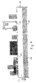
- FIGS. 1 to 4 represent the preferred embodiments, but without them to limit it. All the details shown in the figures belong to the disclosure essential to the invention.
- the press cylinder 3 preferably dimensioned so that the space in it the amount of material to be pressed in volume by volume corresponds to the molded body 7 emerging during a total piston stroke.
- the press cylinder 3 is initially filled gradually under a pressure that is only as large to the material push together in the press cylinder until the corresponding Volume is reached without part of the molded body 7th emerges from the molded tube 4a. Only after full filling of the press cylinder 3, i.e. until the desired volume is reached the entire molded body 7 "is pressed onto one Blow ".
- the internal volumes of the reducer 4 and the molded tube 4a are the same in this preferred embodiment Volume of the emerging molded body 7.
- the emerging molded body 7 should be as homogeneous and dense as possible be and no cracks, air pockets or other waterways exhibit.
- the degree of compaction can be arbitrary built-in reducers 4 (cross-section reduction) selected become.
- both the reducer 4 and the molded tube 4a a very have a very smooth inner surface. That's the only way the pressure pore water escaping between the inner surface of the molded tube 4a and the surface of the to be pressed Shaped body 7 forms a water film, the surface close the shaped body and bind the individual particles.
- the nonwoven fabric lying on the half-shell 8 to rest on. Conditionally due to the weight of the molded body, it pulls the nonwoven fabric with himself with.
- the nonwoven used for wrapping forms at the same time the slideway between molded body 7 and half-shell 8, the sliding of the molded body 7 together with the Nonwoven allowed on the half shell 8.
- the nonwoven supply roll is arranged below the molded tube 4a.
- the width the nonwoven web corresponds to the circumference of the molded body 7 plus Material addition for an overlap of the longitudinal edges to weld or to be able to sew at the overlap.
- the overlap is preferably welded to a Hot air welding machine.
- the end faces of the molded body are through cutting with a steel wire of the strand cutting device 6 flat and are provided with nonwoven caps.
- To this end are round pieces of fleece that are folded 20 cm at the edges can be placed on the end faces. This allows welding with the side nonwoven layer.
- the packaging envelope can initially Shaped body relatively limp, i.e. not tight fitting, enclose, because during the subsequent thermal shrinking process the tight, i.e. tight wrapping is achieved.
- shrink nonwovens the packaging envelope can initially Shaped body relatively limp, i.e. not tight fitting, enclose, because during the subsequent thermal shrinking process the tight, i.e. tight wrapping is achieved.
- the "limp" wrapped molded body through the heat ring 9, the one with a gas burner or infrared radiation equipment or the like is equipped.
- shrink dimensions of approx. 50%, which stabilize after cooling.
- the shrink nonwoven preferably consists of a mixture made of melt fibers and stretched, high-strength fibers.
- the Melt fibers can e.g. undrawn polyester fibers that begin to melt at a temperature of approx. 100 ° C.
- the however, drawn fiber material has a higher melting point (e.g. polyamide 210 ° C, polyester 250 ° C).
- the stake of only melt fibers and the use of bicomponent fibers (Core sheath fibers) is also possible. Both Bicomponent fibers can e.g. the cladding of polyamide fibers and the core of the fibers are made of polyester. Can also the shrink nonwovens also from mixtures of the above Fiber materials or similar raw materials exist.
- the area dimensions of normal nonwovens such as shrink nonwovens can be between 100 g / m 2 and 4000 g / m 2 .
- Nonwovens with a weight per unit area of 250 g / m 2 to 1000 g / m 2 are preferably used.
- the finished components 10 are from the half shell 8 in one special transport container, which is a kind of magazine for has a corresponding number of components 10. It deals swap bodies that are both on a truck as well can be transported by rail or ship. Due to the packaging envelope surrounding the molded body on all sides no pollutants can escape during transport.
- the degree of packing, pressing and the residual water content in the molded body are decisive for the deformation of the Components 10 according to the invention to a compact monolithic Shape whole body. It is supposed to be both ecological Visibility no seepage paths for extraneous water as from construction Visibility no empty gussets and the like remain.
Landscapes
- Engineering & Computer Science (AREA)
- General Engineering & Computer Science (AREA)
- Structural Engineering (AREA)
- Life Sciences & Earth Sciences (AREA)
- General Life Sciences & Earth Sciences (AREA)
- Mining & Mineral Resources (AREA)
- Paleontology (AREA)
- Civil Engineering (AREA)
- Environmental & Geological Engineering (AREA)
- Treatment Of Sludge (AREA)
Description
- 1
- Hydraulischer Antrieb
- 2
- Einfülltrichter für den vorentwässerten Kuchen
- 3
- Preßzylinder
- 4
- Reduzierstück
- 5
- Vliesstoff-Vorratsrolle
- 6
- Strangtrennvorrichtung
- 7
- Formkörper
- 8
- Stützkonstruktion für Formkörper in Form einer "Halbschale"
- 9
- Hitzering zum Schrumpfen der Verpackungshülle
- 10
- Bauelement
- 11
- Transportcontainer
- 12
- Auflastverfüllungsmaterial, das den oberen Teil des gebildeten Baugrundes bildet
- 13
- befahrbares und bebaubares Lagergelände
- Fig. 1
- zeigt in schematischer Darstellung die Herstellung der erfindungsgemäßen Bauelemente 10 mittels einer Kolbenpreßanlage.
- Fig. 2
- zeigt in schematischer Darstellung die subaquatische Ablagerung der erfindungsgemäß hergestellten Bauelemente 10 in einem durch Auffüllung trockenzulegenden Hafenbecken.
- Fig. 3
- zeigt in schematischer Darstellung, wie die in einem durch Auffüllung trockenzulegenden Hafenbecken subaquatisch ablagerten Bauelemente 10 der unteren Schichten durch die die Auflast der darüber abgelagerten Bauelemente 10 beginnen durch Verformung einen monolithischen Gesamtkörper zu bilden.
- Fig. 4
- zeigt in schematischer Darstellung, wie aus den erfindungsgemäß abgelagerten Bauelementen 10 durch die Auflast ein monolithischer Gesamtkörper 14 gebildet wurde, auf dem sich als weiteres Auflastverfüllungsmaterial 12 nicht kontaminiertes Erdmaterial, z.B. Kies, befindet, das den befahrbaren und bebaubaren Baugrund für Containerhallen, Freiflächen usw. bildet.
Claims (19)
- Verwendung von durch Verpressen weitgehendst entwässerten, gegebenenfalls kontaminierten Sedimenten und/oder daraus abgetrennten, gegebenenfalls kontamiminierten Feinsegmenten bzw. Schlick in Form von Bauelementen, die aus verpreßten Formkörpern bestehen, die von einer Verpackungshülle umgeben sind, zur subaquatischen Auffüllung von trockenzulegenden Gewässern, insbesondere von Hafenbecken.
- Verwendung nach Anspruch 1, dadurch gekennzeichnet, daß man als Sediment Ablagerungen in natürlichen oder künstlichen Gewässern, sedimentierte Industrie- und Klärschlämme oder Gemische davon einsetzt.
- Verwendung nach Anspruch 1 und 2, dadurch gekennzeichnet, daß man als Sediment Baggergut aus Häfen und/oder Flüssen und/oder die davon abgetrennten Feinsedimente bzw. den Hafen- oder Flußschlick einsetzt.
- Bauelement nach Anspruch 1 bis 3 zur subaquatischen Auffüllung von trockenzulegenden Gewässern, insbesondere Hafenbecken, dadurch gekennzeichnet daß es aus einem durch Verpressen stark verdichteten, in hohem Maße entwässerten, homogenen Formkörper (7) aus gegebenenfalls kontaminierten Sedimenten oder daraus abgetrennten, gegebenenfalls kontaminierten Feinsedimenten besteht, der allseitig mit einer verformbaren, wasserdurchlässigen Verpackungshülle umgeben ist.
- Bauelement nach Anspruch 4, dadurch gekennzeichnet daß die Verpackungshülle aus einem Textil, vorzugsweise einem Vliesstoff besteht.
- Bauelement nach Anspruch 4, dadurch gekennzeichnet, daß die Verpackungshülle ein Schadstoff-Filter ist, der aus einem vernadelten, vernähten und/oder nähgewirkten Vliesstoff-Vliesstoff-Verbund oder einem Gewebe-Vliesstoff-Verbund besteht, bei dem zwischen den beiden textilen Schichten ein oder mehrere Schadstoffe absorbierende und/oder adsorbierende Materialien eingelagert sind.
- Bauelement nach Anspruch 5 oder 6 , dadurch gekennzeichnet, daß die Hohlräume bzw. die Zwischenräume zwischen den Fasern der textilen Schichten ganz oder teilweise mit Sedimenten, Schlick, einem Tonmineral oder die Schadstoffe ab- und/oder adsorbierenden Materialien ausgefüllt sind.
- Bauelement nach Anspruch 7, dadurch gekennzeichnet, daß die ganz oder gefüllten textilen Schichten feucht gehalten oder mit einem wasserlöslichen Klebstoff auf der nach außen hin zu liegen kommenden Seite oder auf beiden Seiten ganzflä-chig versiegelt sind.
- Bauelement nach Anspruch 4 bis 8, dadurch gekennzeichnet, daß die Verpackungshülle den Formkörper (7) enganliegend umschließt,
- Bauelement nach Anspruch 4 bis 9, dadurch gekennzeichnet, daß der Formkörper(7) aus kontaminiertem Baggergut und/oder davon abgetrenntem kontaminiertem Schlick besteht.
- Bauelement nach Anspruch 4 bis 10, dadurch gekennzeichnet, daß es die Form eines Zylinders hat, vorzugsweise mit einem Durchmesser von 1,25 m und einer Länge von 5 m.
- Verfahren zur Herstellung der Bauelemente nach Anspruch 4 bis 11, dadurch gekennzeichnet, daß man einen durch Verpressen erhaltenen Sediment- und/oder einen Feinsedimentkuchen unter Druckeinwirkung, vorzugsweise unter weiterer Entwässerung, zu einem Formkörper (7) presst und den erhaltenen Formkörper (7) mit einer verformbaren, wasserdurchlässigen Verpackungshülle allseitig umgibt.
- Verfahren nach Anspruch 12, dadurch gekennzeichnet, daß das Formpressen des Kuchens mittels einer Kolbenpresse oder einer anderen hydraulisch arbeitenden Großpresse erfolgt.
- Verfahren nach Anspruch 12 und 13, dadurch gekennzeichnet, daß man den Formkörper (7) direkt in die Verpackungshülle presst.
- Verfahren nach Anspruch 12, dadurch gekennzeichnet, daß man die Verpackungshülle durch spiraliges Einwickeln mit einem endlosen Vliesstoffstreifen und anschließendem Verkappen der Enden des Formkörpers (7) erzeugt.
- Verfahren nach Anspruch 12 bis 15, dadurch gekennzeichnet, daß man die den Formkörper (7) umschließende Verpackungshülle einem thermischen Schrumpfprozeß unterwirft.
- Vorrichtung zur Durchführung des Verfahrens nach Anspruch 12 bis 16, dadurch gekennzeichnet daß sie eine mit einer Verpackungsumhüllungseinrichtung versehene Kolbenpresse darstellt, dessen Preßzylinder (3) einerseits mit einem Einfülltrichter (2) für den Sediment- oder Feinsedimentkuchen und andererseits mit einem Reduzierstück (4) versehen ist, wobei das Reduzierstück (4) mit einem Formrohr (4a) verbunden ist.
- Vorrichtung nach Anspruch 17, dadurch gekennzeichnet, daß das Reduzierstück (4) konisch ausgebildet ist.
- Vorrichtung nach Anspruch 17 und/oder 18, dadurch gekennzeichnet, daß das Reduzierstück (4) mit Einrichtungen zum Austreten des ausgepreßten Wassers versehen ist.
Applications Claiming Priority (2)
| Application Number | Priority Date | Filing Date | Title |
|---|---|---|---|
| DE4331364A DE4331364A1 (de) | 1993-09-15 | 1993-09-15 | Verwendung von stark entwässerten, gegebenenfalls kontaminierten Sedimenten und/oder davon abgetrennten, gegebenenfalls kontaminierten Feinsedimenten in Form von Bauelementen zur subaquatischen Auffüllung von trockenzulegenden Gewässern, insbesondere Hafenbecken |
| DE4331364 | 1993-09-15 |
Publications (3)
| Publication Number | Publication Date |
|---|---|
| EP0642849A1 EP0642849A1 (de) | 1995-03-15 |
| EP0642849B1 EP0642849B1 (de) | 1998-03-04 |
| EP0642849B2 true EP0642849B2 (de) | 2000-12-06 |
Family
ID=6497797
Family Applications (1)
| Application Number | Title | Priority Date | Filing Date |
|---|---|---|---|
| EP94113112A Expired - Lifetime EP0642849B2 (de) | 1993-09-15 | 1994-08-23 | Verwendung von stark entwässerten, ggf. kontaminierten Sedimenten und/oder davon abgetrennten, ggf. kontaminierten Feinsedimenten in Form von Bauelementen zur subaquatischen Auffüllung von trockenzulegenden Gewässern, insbesondere Hafenbecken |
Country Status (2)
| Country | Link |
|---|---|
| EP (1) | EP0642849B2 (de) |
| DE (2) | DE4331364A1 (de) |
Families Citing this family (2)
| Publication number | Priority date | Publication date | Assignee | Title |
|---|---|---|---|---|
| DE102006028473A1 (de) * | 2006-06-21 | 2007-12-27 | Winter Von Adlersflügel, Johannes Bernhard | Füllaggregat |
| DE202010008093U1 (de) * | 2010-07-16 | 2011-08-09 | Roland Draier | Vorrichtung zum Befüllen von körnigen, pulverförmigen, schüttfähigen Materialien in ein aus Geotextilmaterial gefertigtes Behältnis |
Family Cites Families (2)
| Publication number | Priority date | Publication date | Assignee | Title |
|---|---|---|---|---|
| DE3150993A1 (de) * | 1981-12-23 | 1983-06-30 | Ed. Züblin AG, 7000 Stuttgart | Verfahren zur entsorgung fliessender und stehender gewaesser von feinkoernigen sedimenten |
| CA2028251C (en) * | 1990-10-22 | 1999-05-11 | Pierre Lucien Cote | Process and barrier for the containment of wastes |
-
1993
- 1993-09-15 DE DE4331364A patent/DE4331364A1/de not_active Withdrawn
-
1994
- 1994-08-23 EP EP94113112A patent/EP0642849B2/de not_active Expired - Lifetime
- 1994-08-23 DE DE59405356T patent/DE59405356D1/de not_active Expired - Fee Related
Non-Patent Citations (1)
| Title |
|---|
| Seiten 1-6 aus Sonderdruck "Wasser und Boden" Heft 1, 24.Jahrgang, Seiten 20-24, Jan 72 † |
Also Published As
| Publication number | Publication date |
|---|---|
| DE59405356D1 (de) | 1998-04-09 |
| EP0642849B1 (de) | 1998-03-04 |
| DE4331364A1 (de) | 1995-03-16 |
| EP0642849A1 (de) | 1995-03-15 |
Similar Documents
| Publication | Publication Date | Title |
|---|---|---|
| US11007742B2 (en) | Dynamic separation and filtration | |
| US10675829B2 (en) | Dynamic separation and filtration | |
| US10526229B2 (en) | Dynamic separation and filtration | |
| EP0373460B1 (de) | Verfahren zur Deponierung von Abfällen | |
| EP0026301B1 (de) | Verfahren zum Beseitigen oder Zwischenlagern von Abfällen | |
| DE3445127C2 (de) | ||
| US20060102565A1 (en) | System and method for dewatering sludge, slurry or sediment | |
| DE2320350A1 (de) | Anlage zur manipulation von schlaemmen, insbesondere von industrieschlaemmen | |
| DE3004682A1 (de) | Verfahren und einrichtung zum beseitigen von schlaemmen aus industrie- und hausklaergruben o.dgl. einrichtungen | |
| EP0642849B2 (de) | Verwendung von stark entwässerten, ggf. kontaminierten Sedimenten und/oder davon abgetrennten, ggf. kontaminierten Feinsedimenten in Form von Bauelementen zur subaquatischen Auffüllung von trockenzulegenden Gewässern, insbesondere Hafenbecken | |
| DE60316476T2 (de) | Vorrichtung zur verhinderung des mitlaufens von feinpartikeln | |
| WO1996002705A1 (de) | Permeables behandlungsbett zur reinigung kontaminierter grundwasserströme in situ | |
| DE69624315T2 (de) | Verfahren zum Entfernen einer Flüssigkeit aus einer Mischung | |
| WO1989007493A1 (fr) | Depot temporaire ou definitif de dechets dangereux et procede d'installation de depots de dechets | |
| CN120515788B (zh) | 含砷污物的填埋场结构及安全填埋方法 | |
| CN107905209A (zh) | 卫生填埋场生态修复用渗滤液收集装置及其施工方法 | |
| DE3519225A1 (de) | Verfahren zur errichtung von fuer hydraulische bergehalden benoetigten boeschungsstuetzkoerpern, sowie einrichtung zur durchfuehrung des verfahrens | |
| AT404608B (de) | Vorrichtung zum dekontaminieren von grundwasserströmen | |
| DE4134195A1 (de) | Verfahren zum abtragen und einbringen von sedimenten, schlicken oder anderen materialien von einem bzw. auf einen gewaesserboden und vorrichtung zur durchfuehrung des verfahrens | |
| DE60018985T2 (de) | Verfahren zum aufbau eines systems zum schutz vor überschwemmungen | |
| EP0482314B1 (de) | Verfahren zum schadlosen Deponieren von verfestigten anorganischen Reststoffen und Abfällen in aufgelassenen Steinbrüchen | |
| DE4221198A1 (de) | Verfahren zur Entfernung von wasserlöslichen sorbierbaren Schadstoffen aus dem abströmenden Grundwasser in der Umgebung eines Kontaminationsherdes | |
| DE3729653A1 (de) | Verfahren zum vorsorglichen oder nachtraeglichen schutz des um eine deponie anstehenden erdreichs gegen aus der deponie austretende schadfluessigkeit | |
| DE19914839B4 (de) | Verfahren zum Erstellen einer reaktiven Schmalwand | |
| DE3707033C2 (de) |
Legal Events
| Date | Code | Title | Description |
|---|---|---|---|
| PUAI | Public reference made under article 153(3) epc to a published international application that has entered the european phase |
Free format text: ORIGINAL CODE: 0009012 |
|
| AK | Designated contracting states |
Kind code of ref document: A1 Designated state(s): BE DE FR GB IT NL |
|
| RIN1 | Information on inventor provided before grant (corrected) |
Inventor name: BOEGE,ERNST-HEINRICH Inventor name: MUELLER,VOLKARD Inventor name: JOHANNSSEN,KARSTEN, DIPL. ING. |
|
| 17P | Request for examination filed |
Effective date: 19950527 |
|
| 17Q | First examination report despatched |
Effective date: 19970115 |
|
| RAP1 | Party data changed (applicant data changed or rights of an application transferred) |
Owner name: HEINRICH HIRDES GMBH Owner name: NAUE-FASERTECHNIK GMBH & CO. KG |
|
| GRAG | Despatch of communication of intention to grant |
Free format text: ORIGINAL CODE: EPIDOS AGRA |
|
| GRAG | Despatch of communication of intention to grant |
Free format text: ORIGINAL CODE: EPIDOS AGRA |
|
| GRAH | Despatch of communication of intention to grant a patent |
Free format text: ORIGINAL CODE: EPIDOS IGRA |
|
| GRAH | Despatch of communication of intention to grant a patent |
Free format text: ORIGINAL CODE: EPIDOS IGRA |
|
| GRAA | (expected) grant |
Free format text: ORIGINAL CODE: 0009210 |
|
| AK | Designated contracting states |
Kind code of ref document: B1 Designated state(s): BE DE FR GB IT NL |
|
| REF | Corresponds to: |
Ref document number: 59405356 Country of ref document: DE Date of ref document: 19980409 |
|
| ITF | It: translation for a ep patent filed | ||
| ET | Fr: translation filed | ||
| GBT | Gb: translation of ep patent filed (gb section 77(6)(a)/1977) |
Effective date: 19980514 |
|
| PLBQ | Unpublished change to opponent data |
Free format text: ORIGINAL CODE: EPIDOS OPPO |
|
| PLBI | Opposition filed |
Free format text: ORIGINAL CODE: 0009260 |
|
| PLBF | Reply of patent proprietor to notice(s) of opposition |
Free format text: ORIGINAL CODE: EPIDOS OBSO |
|
| 26 | Opposition filed |
Opponent name: HUESKER SYNTHETIC GMBH & CO. Effective date: 19981204 |
|
| NLR1 | Nl: opposition has been filed with the epo |
Opponent name: HUESKER SYNTHETIC GMBH & CO. |
|
| PLBF | Reply of patent proprietor to notice(s) of opposition |
Free format text: ORIGINAL CODE: EPIDOS OBSO |
|
| PLBF | Reply of patent proprietor to notice(s) of opposition |
Free format text: ORIGINAL CODE: EPIDOS OBSO |
|
| PLAW | Interlocutory decision in opposition |
Free format text: ORIGINAL CODE: EPIDOS IDOP |
|
| PLAW | Interlocutory decision in opposition |
Free format text: ORIGINAL CODE: EPIDOS IDOP |
|
| PUAH | Patent maintained in amended form |
Free format text: ORIGINAL CODE: 0009272 |
|
| STAA | Information on the status of an ep patent application or granted ep patent |
Free format text: STATUS: PATENT MAINTAINED AS AMENDED |
|
| 27A | Patent maintained in amended form |
Effective date: 20001206 |
|
| AK | Designated contracting states |
Kind code of ref document: B2 Designated state(s): BE DE FR GB IT NL |
|
| ITF | It: translation for a ep patent filed | ||
| NLR2 | Nl: decision of opposition | ||
| ET3 | Fr: translation filed ** decision concerning opposition | ||
| NLR3 | Nl: receipt of modified translations in the netherlands language after an opposition procedure | ||
| GBTA | Gb: translation of amended ep patent filed (gb section 77(6)(b)/1977) | ||
| REG | Reference to a national code |
Ref country code: GB Ref legal event code: IF02 |
|
| PGFP | Annual fee paid to national office [announced via postgrant information from national office to epo] |
Ref country code: GB Payment date: 20020821 Year of fee payment: 9 |
|
| PGFP | Annual fee paid to national office [announced via postgrant information from national office to epo] |
Ref country code: FR Payment date: 20020830 Year of fee payment: 9 Ref country code: NL Payment date: 20020830 Year of fee payment: 9 |
|
| PGFP | Annual fee paid to national office [announced via postgrant information from national office to epo] |
Ref country code: BE Payment date: 20020913 Year of fee payment: 9 |
|
| PG25 | Lapsed in a contracting state [announced via postgrant information from national office to epo] |
Ref country code: GB Free format text: LAPSE BECAUSE OF NON-PAYMENT OF DUE FEES Effective date: 20030823 |
|
| PG25 | Lapsed in a contracting state [announced via postgrant information from national office to epo] |
Ref country code: BE Free format text: LAPSE BECAUSE OF NON-PAYMENT OF DUE FEES Effective date: 20030831 |
|
| BERE | Be: lapsed |
Owner name: *HEINRICH HIRDES GM.B.H. Effective date: 20030831 Owner name: *NAUE-FASERTECHNIK G.M.B.H. & CO. K.G. Effective date: 20030831 |
|
| PG25 | Lapsed in a contracting state [announced via postgrant information from national office to epo] |
Ref country code: NL Free format text: LAPSE BECAUSE OF NON-PAYMENT OF DUE FEES Effective date: 20040301 |
|
| GBPC | Gb: european patent ceased through non-payment of renewal fee | ||
| PG25 | Lapsed in a contracting state [announced via postgrant information from national office to epo] |
Ref country code: FR Free format text: LAPSE BECAUSE OF NON-PAYMENT OF DUE FEES Effective date: 20040430 |
|
| NLV4 | Nl: lapsed or anulled due to non-payment of the annual fee |
Effective date: 20040301 |
|
| REG | Reference to a national code |
Ref country code: FR Ref legal event code: ST |
|
| PG25 | Lapsed in a contracting state [announced via postgrant information from national office to epo] |
Ref country code: IT Free format text: LAPSE BECAUSE OF NON-PAYMENT OF DUE FEES;WARNING: LAPSES OF ITALIAN PATENTS WITH EFFECTIVE DATE BEFORE 2007 MAY HAVE OCCURRED AT ANY TIME BEFORE 2007. THE CORRECT EFFECTIVE DATE MAY BE DIFFERENT FROM THE ONE RECORDED. Effective date: 20050823 |
|
| PGFP | Annual fee paid to national office [announced via postgrant information from national office to epo] |
Ref country code: DE Payment date: 20070817 Year of fee payment: 14 |
|
| PG25 | Lapsed in a contracting state [announced via postgrant information from national office to epo] |
Ref country code: DE Free format text: LAPSE BECAUSE OF NON-PAYMENT OF DUE FEES Effective date: 20090303 |