EP0642873A1 - Appareillage de soudage avec gaz de protection - Google Patents
Appareillage de soudage avec gaz de protection Download PDFInfo
- Publication number
- EP0642873A1 EP0642873A1 EP94110154A EP94110154A EP0642873A1 EP 0642873 A1 EP0642873 A1 EP 0642873A1 EP 94110154 A EP94110154 A EP 94110154A EP 94110154 A EP94110154 A EP 94110154A EP 0642873 A1 EP0642873 A1 EP 0642873A1
- Authority
- EP
- European Patent Office
- Prior art keywords
- sleeve
- welding
- diameter
- end wall
- protective
- Prior art date
- Legal status (The legal status is an assumption and is not a legal conclusion. Google has not performed a legal analysis and makes no representation as to the accuracy of the status listed.)
- Granted
Links
- 238000003466 welding Methods 0.000 title claims abstract description 49
- 230000001681 protective effect Effects 0.000 claims abstract description 39
- 229910052751 metal Inorganic materials 0.000 claims abstract description 10
- 239000002184 metal Substances 0.000 claims abstract description 10
- 239000007789 gas Substances 0.000 claims description 22
- XLYOFNOQVPJJNP-UHFFFAOYSA-N water Substances O XLYOFNOQVPJJNP-UHFFFAOYSA-N 0.000 claims description 14
- 239000011261 inert gas Substances 0.000 claims description 12
- 238000001816 cooling Methods 0.000 claims description 11
- 229910052582 BN Inorganic materials 0.000 claims description 3
- PZNSFCLAULLKQX-UHFFFAOYSA-N Boron nitride Chemical compound N#B PZNSFCLAULLKQX-UHFFFAOYSA-N 0.000 claims description 3
- 229910010293 ceramic material Inorganic materials 0.000 claims description 3
- 238000010992 reflux Methods 0.000 claims description 3
- 239000000463 material Substances 0.000 claims 1
- 238000009413 insulation Methods 0.000 description 3
- 230000003647 oxidation Effects 0.000 description 3
- 238000007254 oxidation reaction Methods 0.000 description 3
- RYGMFSIKBFXOCR-UHFFFAOYSA-N Copper Chemical compound [Cu] RYGMFSIKBFXOCR-UHFFFAOYSA-N 0.000 description 2
- 230000015572 biosynthetic process Effects 0.000 description 2
- 229910052802 copper Inorganic materials 0.000 description 2
- 239000010949 copper Substances 0.000 description 2
- 238000005192 partition Methods 0.000 description 2
- 230000035515 penetration Effects 0.000 description 2
- 229910001369 Brass Inorganic materials 0.000 description 1
- RTAQQCXQSZGOHL-UHFFFAOYSA-N Titanium Chemical compound [Ti] RTAQQCXQSZGOHL-UHFFFAOYSA-N 0.000 description 1
- QVGXLLKOCUKJST-UHFFFAOYSA-N atomic oxygen Chemical compound [O] QVGXLLKOCUKJST-UHFFFAOYSA-N 0.000 description 1
- 239000010951 brass Substances 0.000 description 1
- 238000011109 contamination Methods 0.000 description 1
- 238000005520 cutting process Methods 0.000 description 1
- 238000004519 manufacturing process Methods 0.000 description 1
- 150000001247 metal acetylides Chemical class 0.000 description 1
- 238000000034 method Methods 0.000 description 1
- 239000001301 oxygen Substances 0.000 description 1
- 229910052760 oxygen Inorganic materials 0.000 description 1
- RVTZCBVAJQQJTK-UHFFFAOYSA-N oxygen(2-);zirconium(4+) Chemical compound [O-2].[O-2].[Zr+4] RVTZCBVAJQQJTK-UHFFFAOYSA-N 0.000 description 1
- -1 silicon carbide Chemical class 0.000 description 1
- HBMJWWWQQXIZIP-UHFFFAOYSA-N silicon carbide Chemical compound [Si+]#[C-] HBMJWWWQQXIZIP-UHFFFAOYSA-N 0.000 description 1
- 229910010271 silicon carbide Inorganic materials 0.000 description 1
- 239000010936 titanium Substances 0.000 description 1
- 229910052719 titanium Inorganic materials 0.000 description 1
- 229910001928 zirconium oxide Inorganic materials 0.000 description 1
Images

Classifications
-
- B—PERFORMING OPERATIONS; TRANSPORTING
- B23—MACHINE TOOLS; METAL-WORKING NOT OTHERWISE PROVIDED FOR
- B23K—SOLDERING OR UNSOLDERING; WELDING; CLADDING OR PLATING BY SOLDERING OR WELDING; CUTTING BY APPLYING HEAT LOCALLY, e.g. FLAME CUTTING; WORKING BY LASER BEAM
- B23K9/00—Arc welding or cutting
- B23K9/32—Accessories
- B23K9/325—Devices for supplying or evacuating shielding gas
Definitions
- the invention relates to a device for gas-shielded arc welding with a metallic nozzle body guiding a welding wire, a sleeve surrounding it at a distance and a protective body attached to the front open end of the sleeve or integrally formed with the sleeve and having an end wall.
- inert gas welding torches with a metallic nozzle body and a sleeve surrounding it at a distance are known.
- this type of inert gas welding torch the welding and metal splashes that occur during welding can get into the interior of the sleeve, where they weld to the nozzle body and once interfere with and even interrupt the wire feed and can also lead to the formation of a bridge, so that a current bridge between the current-carrying nozzle body and the non-current-carrying sleeve. If you then touch the workpiece with the sleeve, damage is inevitable.
- PCT / WO 93/13934 furthermore discloses a protective gas welding torch which has a protective body with an end wall in the region of the front end of the sleeve.
- the front wall of the protective body serves the metal and Catch welding spatter and not to get into the interior of the sleeve.
- the end wall has a coaxial central hole and a plurality of circumferentially distributed gas outlet openings at a distance therefrom.
- the central hole is axially aligned with the nozzle axis of the nozzle body, so that the welding wire exits through the central hole and closes it.
- the formation of the gas outlet openings is complex in terms of production technology.
- there is a risk that these gas outlet openings will be clogged or at least reduced in size by metal and welding spatter resulting from the welding process, so that the gas has fewer exit possibilities.
- the gas outlet openings are difficult to clean.
- the object of the present invention is to design a device for inert gas welding of the type known from PCT / WO 93/13934 in such a way that the disadvantages known in the prior art are avoided.
- the protective body can be manufactured more easily, quickly and cost-effectively.
- the largest possible opening had to be present at the front open end of the sleeve so that the protective gas escaping there covered as large an area of the workpiece to be welded as possible. to effectively protect the area to be welded against oxidation by atmospheric oxygen.
- the gas outlet openings known from PCT / WO 93 13934 at a distance from the central opening also served this purpose.
- the gas passes through the opening according to the invention in the end wall of the protective body, the diameter of which, owing to the end wall, is smaller than that of the sleeve, the gas flow tends to widen after exiting this opening.
- a much larger area with a protective gas atmosphere is thus available on the workpiece itself than at the point of exit of the gas from the opening, which ensures effective protection of the workpiece against oxidation.
- the fact that the gas flow widens after it emerges from the opening according to the invention has the further advantage that the direction of movement of the metal and welding spatter is influenced thereby. These are preferably sprayed at such an angle that they are guided past the end face of the welding torch, which reduces the contamination of the end wall of the protective body.
- the protective body is non-metallic.
- the protective body can consist of a boron nitride mixed ceramic material which has oxide and / or carbide components to reduce the surface adhesion.
- the diameter of the opening which has the end wall can be less than or equal to the diameter of the nozzle body.
- the penetration of welding spatter into the interior of the sleeve is thereby prevented even more effectively.
- the previously described efforts of the gas flow to widen when it has passed through the end wall of the protective body also lead to effective protection of the workpiece against oxidation if the diameter of the opening in the end wall is smaller or is equal to the diameter of the nozzle body.
- the diameter of the opening can also be larger than that Be nozzle body without affecting the success of the invention.
- the protective body can also be made of metal and in one piece with the sleeve. It can be provided that a water cooling is connected to the inner wall of the sleeve. This water cooling then serves to dissipate the heat generated during inert gas welding.
- the water cooling is preferably designed as reflux cooling so that the heated water can always be removed and replaced by new cold water.
- the invention also relates to a protective body for a device for inert gas welding with a welding wire, with an end wall, characterized in that the end wall has a single opening with a diameter which allows the welding wire and a protective gas to exit simultaneously.
- the invention further relates to an end wall of an apparatus for inert gas welding with a welding wire, characterized in that it has a single opening with a diameter which enables the welding wire and an inert gas to exit simultaneously.
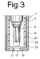
- the welding torch 1 shown in FIGS. 1 to 3 has a torch head 3 with a nozzle body 5, through which the welding wire, not shown, is guided to the welding point.
- the feed is located on the welding machine and takes place through a hose package in which the electrical energy, the wire and the shielding gas are also fed to the torch.
- the burner head 3 is surrounded by a sleeve 9, preferably made of copper, so that the protective gas exits into an annular channel between the nozzle body 5 and the sleeve 9.
- the sleeve 9 in a first embodiment, which is shown in FIGS. 1 and 2, has a protective body 15 at its front open end 11, which consists of an end wall 17 and a collar 19 projecting into the interior of the sleeve 9.
- the protective body 15 can be connected to the sleeve 9 in various ways.
- the collar 19 can have an external thread with which it is screwed into a corresponding internal thread of the sleeve 9. But it can also be pressed into the open end of the sleeve.
- the protective body 15 and the sleeve 9 are integrally formed.
- the diameter of the opening 21 preferably corresponds to that of the contact nozzle in the nozzle body 5. In principle, however, the diameter of the opening 21 can be larger, smaller or equal to the diameter of the nozzle body 5.
- the opening 21 is positioned in the end wall 17 so that the welding wire can emerge from the nozzle body 5 and can reach the outside through the opening 21.
- the protective body 15 preferably consists of a boron nitride mixed ceramic material.
- the properties of the protective body 15 can be further improved, with the success that welding and metal spatter from the weld are thrown back, essentially bounce off the end wall 17 of the protective body 15. The remaining metal residues can be removed by bracing.
- borides such as titanium boride and / or oxides, such as zirconium oxide and / or carbides, such as silicon carbide
- FIG. 3 A second embodiment of the cutting torch 1 according to the invention is shown in FIG. 3 and differs from the first embodiment in that the protective body 15 is made of metal and preferably in one piece with the sleeve 9.
- the metallic protective body 15 can, however, also be connected to the sleeve 9 as a separate part, as has already been described for the protective body 15 according to the first embodiment. Since a large amount of heat is generated during inert gas welding, in this embodiment of the welding torch 1 according to the invention it is provided that water cooling 23 is connected to the inner wall of the sleeve 9.
- the wall 25 of the water cooling 23 pointing in the direction of the nozzle body 5 additionally has an insulation 27.
- the water cooling 23 is designed in the form of a reflux cooling.
- the partition is preferably made as a milled part and made of copper or brass.
- the heated water can be removed and always replaced with cold water.
- the water is supplied and discharged in a manner known per se via the hose package.
- the nozzle body 5 is also surrounded by insulation. It is also possible for only the nozzle body 5 to have insulation, for example in the form of an insulating sleeve.
Landscapes
- Engineering & Computer Science (AREA)
- Physics & Mathematics (AREA)
- Plasma & Fusion (AREA)
- Mechanical Engineering (AREA)
- Arc Welding In General (AREA)
Priority Applications (6)
| Application Number | Priority Date | Filing Date | Title |
|---|---|---|---|
| BR9403543A BR9403543A (pt) | 1993-09-14 | 1994-09-13 | Dispositivo para soldadura a arco com proteção de gás, corpo de proteção e parede frontal |
| EP94927616A EP0759829B1 (fr) | 1993-09-14 | 1994-09-14 | Procede de nettoyage d'un dispositif de soudage a l'arc sous protection gazeuse |
| PCT/EP1994/003089 WO1995007788A1 (fr) | 1993-09-14 | 1994-09-14 | Procede de nettoyage d'un dispositif de soudage a l'arc sous protection gazeuse |
| ES94927616T ES2122327T3 (es) | 1993-09-14 | 1994-09-14 | Procedimiento para limpiar un dispositivo de soldadura en atmosfera protectora. |
| AT94927616T ATE170121T1 (de) | 1993-09-14 | 1994-09-14 | Verfahren zum reinigen einer vorrichtung zum schutzgasschweissen |
| DE59406796T DE59406796D1 (de) | 1993-09-14 | 1994-09-14 | Verfahren zum reinigen einer vorrichtung zum schutzgasschweissen |
Applications Claiming Priority (2)
| Application Number | Priority Date | Filing Date | Title |
|---|---|---|---|
| DE9313893U | 1993-09-14 | ||
| DE9313893U DE9313893U1 (de) | 1993-09-14 | 1993-09-14 | Vorrichtung zum Schutzgasschweißen |
Publications (2)
| Publication Number | Publication Date |
|---|---|
| EP0642873A1 true EP0642873A1 (fr) | 1995-03-15 |
| EP0642873B1 EP0642873B1 (fr) | 1998-01-07 |
Family
ID=6898096
Family Applications (1)
| Application Number | Title | Priority Date | Filing Date |
|---|---|---|---|
| EP94110154A Expired - Lifetime EP0642873B1 (fr) | 1993-09-14 | 1994-06-29 | Appareillage de soudage avec gaz de protection |
Country Status (4)
| Country | Link |
|---|---|
| EP (1) | EP0642873B1 (fr) |
| AT (1) | ATE161766T1 (fr) |
| DE (2) | DE9313893U1 (fr) |
| ES (1) | ES2114093T3 (fr) |
Families Citing this family (1)
| Publication number | Priority date | Publication date | Assignee | Title |
|---|---|---|---|---|
| WO1994019136A1 (fr) * | 1993-02-23 | 1994-09-01 | Bavaria-Tech Werner Schlattl | Buse de sortie de gaz destinee a l'utilisation dans des installations ou appareils de soudage |
Citations (3)
| Publication number | Priority date | Publication date | Assignee | Title |
|---|---|---|---|---|
| US4788401A (en) * | 1987-08-17 | 1988-11-29 | C-K Systematics, Inc. Div. Of Conley & Kleppen, Int'l. | Inert gas welding torch |
| US4916270A (en) * | 1989-02-06 | 1990-04-10 | Century Mfg. Co. | Mig welder cutting head attachment |
| WO1993013934A1 (fr) * | 1992-01-16 | 1993-07-22 | Elektroschmelzwerk Kempten Gmbh | Dispositif de soudage et de decoupage a l'arc |
-
1993
- 1993-09-14 DE DE9313893U patent/DE9313893U1/de not_active Expired - Lifetime
-
1994
- 1994-06-29 DE DE59404936T patent/DE59404936D1/de not_active Expired - Fee Related
- 1994-06-29 AT AT94110154T patent/ATE161766T1/de not_active IP Right Cessation
- 1994-06-29 ES ES94110154T patent/ES2114093T3/es not_active Expired - Lifetime
- 1994-06-29 EP EP94110154A patent/EP0642873B1/fr not_active Expired - Lifetime
Patent Citations (3)
| Publication number | Priority date | Publication date | Assignee | Title |
|---|---|---|---|---|
| US4788401A (en) * | 1987-08-17 | 1988-11-29 | C-K Systematics, Inc. Div. Of Conley & Kleppen, Int'l. | Inert gas welding torch |
| US4916270A (en) * | 1989-02-06 | 1990-04-10 | Century Mfg. Co. | Mig welder cutting head attachment |
| WO1993013934A1 (fr) * | 1992-01-16 | 1993-07-22 | Elektroschmelzwerk Kempten Gmbh | Dispositif de soudage et de decoupage a l'arc |
Also Published As
| Publication number | Publication date |
|---|---|
| EP0642873B1 (fr) | 1998-01-07 |
| ES2114093T3 (es) | 1998-05-16 |
| DE9313893U1 (de) | 1993-11-11 |
| ATE161766T1 (de) | 1998-01-15 |
| DE59404936D1 (de) | 1998-02-12 |
Similar Documents
| Publication | Publication Date | Title |
|---|---|---|
| DE19520616C2 (de) | Düse für eine Schutzgas-Lichtbogenschweißmaschine, Schutzgas-Lichtbogenschweißmaschine mit einer Düse und Brenner hierfür | |
| DE69020885T2 (de) | Plasmabogenbrenner mit langer Düse. | |
| DE68929313T2 (de) | Düsenschutz für Plasmalichtbogenschweissbrenner | |
| DE102011088433A1 (de) | Verfahren und Plasmalichtbogenbrennersystem zum Markieren und Schneiden von Werkstücken mit dem selben Satz an Hilfsstoffen | |
| DE2130394A1 (de) | Lichtbogenschneidverfahren | |
| DE112019006401T5 (de) | Wig-schweissbrenner mit verengter düse zum punktschweissen sowie darin verwendete elektrodendüse | |
| DE2615679A1 (de) | Lichtbogen-metallspritzgeraet | |
| DE2306022A1 (de) | Plasmabrenner mit achsialzufuhr des stabilisierenden gases | |
| EP0294324A1 (fr) | Outil d'usinage au laser | |
| DE102019100581A1 (de) | Gasdüse zum Ausströmen eines Schutzgasstromes und Brennerhals mit einer Gasdüse | |
| WO2017178580A1 (fr) | Dispositif d'usinage d'une surface d'une pièce au moyen d'un faisceau laser et procédé permettant de faire fonctionner ledit dispositif | |
| EP0168810B1 (fr) | Chalumeau à souder pour soudage par plasma-MIG | |
| DE4239822A1 (fr) | ||
| DE3877583T2 (de) | Brenner fuer das plasma schneiden und schweissen. | |
| DE3834224C2 (de) | Lichtbogen-Schutzgasschweißbrenner zum Schweißen an schwer zugänglichen Stellen | |
| DE2217770A1 (de) | Schweiss- oder schneidbrenner mit rauchentzug | |
| DE69300563T2 (de) | Lichtbogenplasmabrenner mit konische Bohrung enthaltender Elektrode. | |
| DE2654144A1 (de) | Verfahren und brenner zum aufrechterhalten von koaxialen mehrfachlichtboegen | |
| DE102017121722B4 (de) | Brennerkörper zum thermischen Fügen, Brenner mit Brennerkörper und Fügevorrichtung | |
| DE2813804A1 (de) | Plasmabogen schweiss- und schneidgeraet | |
| EP0642873B1 (fr) | Appareillage de soudage avec gaz de protection | |
| DE3524034A1 (de) | Vorrichtung zum plasmaschneiden von metallischen werkstuecken | |
| DE69704036T2 (de) | Verfahren und Vorrichtung zur Verringerung der Entstehung von Ozon beim Lichtbogen-Schutzgasschweissen | |
| EP0357694B1 (fr) | Dispositif pour produire une enveloppe de gaz inerte de protection lors de pulverisation par plasma | |
| EP2487003B1 (fr) | Pistolet soudeur d'un appareil de soudure à arc |
Legal Events
| Date | Code | Title | Description |
|---|---|---|---|
| PUAI | Public reference made under article 153(3) epc to a published international application that has entered the european phase |
Free format text: ORIGINAL CODE: 0009012 |
|
| AK | Designated contracting states |
Kind code of ref document: A1 Designated state(s): AT BE CH DE ES FR GB IT LI NL PT |
|
| RAX | Requested extension states of the european patent have changed |
Free format text: SI PAYMENT 940912 |
|
| 17P | Request for examination filed |
Effective date: 19950913 |
|
| 17Q | First examination report despatched |
Effective date: 19960809 |
|
| GRAG | Despatch of communication of intention to grant |
Free format text: ORIGINAL CODE: EPIDOS AGRA |
|
| GRAG | Despatch of communication of intention to grant |
Free format text: ORIGINAL CODE: EPIDOS AGRA |
|
| GRAH | Despatch of communication of intention to grant a patent |
Free format text: ORIGINAL CODE: EPIDOS IGRA |
|
| GRAH | Despatch of communication of intention to grant a patent |
Free format text: ORIGINAL CODE: EPIDOS IGRA |
|
| RAP3 | Party data changed (applicant data changed or rights of an application transferred) |
Owner name: FRIEDRICH, BERND |
|
| GRAA | (expected) grant |
Free format text: ORIGINAL CODE: 0009210 |
|
| AK | Designated contracting states |
Kind code of ref document: B1 Designated state(s): AT BE CH DE ES FR GB IT LI NL PT |
|
| AX | Request for extension of the european patent |
Free format text: SI PAYMENT 940912 |
|
| REF | Corresponds to: |
Ref document number: 161766 Country of ref document: AT Date of ref document: 19980115 Kind code of ref document: T |
|
| REG | Reference to a national code |
Ref country code: CH Ref legal event code: EP |
|
| REF | Corresponds to: |
Ref document number: 59404936 Country of ref document: DE Date of ref document: 19980212 |
|
| ITF | It: translation for a ep patent filed | ||
| PG25 | Lapsed in a contracting state [announced via postgrant information from national office to epo] |
Ref country code: PT Free format text: LAPSE BECAUSE OF FAILURE TO SUBMIT A TRANSLATION OF THE DESCRIPTION OR TO PAY THE FEE WITHIN THE PRESCRIBED TIME-LIMIT Effective date: 19980407 |
|
| GBT | Gb: translation of ep patent filed (gb section 77(6)(a)/1977) |
Effective date: 19980327 |
|
| ET | Fr: translation filed | ||
| REG | Reference to a national code |
Ref country code: CH Ref legal event code: NV Representative=s name: TROESCH SCHEIDEGGER WERNER AG |
|
| REG | Reference to a national code |
Ref country code: ES Ref legal event code: FG2A Ref document number: 2114093 Country of ref document: ES Kind code of ref document: T3 |
|
| PLBE | No opposition filed within time limit |
Free format text: ORIGINAL CODE: 0009261 |
|
| STAA | Information on the status of an ep patent application or granted ep patent |
Free format text: STATUS: NO OPPOSITION FILED WITHIN TIME LIMIT |
|
| 26N | No opposition filed | ||
| REG | Reference to a national code |
Ref country code: FR Ref legal event code: CL |
|
| PGFP | Annual fee paid to national office [announced via postgrant information from national office to epo] |
Ref country code: NL Payment date: 20000630 Year of fee payment: 7 |
|
| PGFP | Annual fee paid to national office [announced via postgrant information from national office to epo] |
Ref country code: BE Payment date: 20000714 Year of fee payment: 7 |
|
| PG25 | Lapsed in a contracting state [announced via postgrant information from national office to epo] |
Ref country code: BE Free format text: LAPSE BECAUSE OF NON-PAYMENT OF DUE FEES Effective date: 20010630 |
|
| BERE | Be: lapsed |
Owner name: FRIEDRICH BERND Effective date: 20010630 |
|
| PG25 | Lapsed in a contracting state [announced via postgrant information from national office to epo] |
Ref country code: NL Free format text: LAPSE BECAUSE OF NON-PAYMENT OF DUE FEES Effective date: 20020101 |
|
| REG | Reference to a national code |
Ref country code: GB Ref legal event code: IF02 |
|
| NLV4 | Nl: lapsed or anulled due to non-payment of the annual fee |
Effective date: 20020101 |
|
| PGFP | Annual fee paid to national office [announced via postgrant information from national office to epo] |
Ref country code: GB Payment date: 20041126 Year of fee payment: 11 Ref country code: FR Payment date: 20041126 Year of fee payment: 11 Ref country code: DE Payment date: 20041126 Year of fee payment: 11 Ref country code: CH Payment date: 20041126 Year of fee payment: 11 |
|
| PGFP | Annual fee paid to national office [announced via postgrant information from national office to epo] |
Ref country code: AT Payment date: 20041129 Year of fee payment: 11 |
|
| PGFP | Annual fee paid to national office [announced via postgrant information from national office to epo] |
Ref country code: ES Payment date: 20041130 Year of fee payment: 11 |
|
| PG25 | Lapsed in a contracting state [announced via postgrant information from national office to epo] |
Ref country code: IT Free format text: LAPSE BECAUSE OF NON-PAYMENT OF DUE FEES Effective date: 20050629 Ref country code: AT Free format text: LAPSE BECAUSE OF NON-PAYMENT OF DUE FEES Effective date: 20050629 |
|
| PG25 | Lapsed in a contracting state [announced via postgrant information from national office to epo] |
Ref country code: LI Free format text: LAPSE BECAUSE OF NON-PAYMENT OF DUE FEES Effective date: 20050630 Ref country code: ES Free format text: LAPSE BECAUSE OF NON-PAYMENT OF DUE FEES Effective date: 20050630 Ref country code: CH Free format text: LAPSE BECAUSE OF NON-PAYMENT OF DUE FEES Effective date: 20050630 |
|
| PG25 | Lapsed in a contracting state [announced via postgrant information from national office to epo] |
Ref country code: DE Free format text: LAPSE BECAUSE OF NON-PAYMENT OF DUE FEES Effective date: 20060103 |
|
| REG | Reference to a national code |
Ref country code: CH Ref legal event code: PL |
|
| PG25 | Lapsed in a contracting state [announced via postgrant information from national office to epo] |
Ref country code: FR Free format text: LAPSE BECAUSE OF NON-PAYMENT OF DUE FEES Effective date: 20060228 |
|
| GBPC | Gb: european patent ceased through non-payment of renewal fee |
Effective date: 20050629 |
|
| REG | Reference to a national code |
Ref country code: FR Ref legal event code: ST Effective date: 20060228 |
|
| REG | Reference to a national code |
Ref country code: ES Ref legal event code: FD2A Effective date: 20050630 |