EP0642880B1 - Changeur d'outil pour un centre d'usinage - Google Patents
Changeur d'outil pour un centre d'usinage Download PDFInfo
- Publication number
- EP0642880B1 EP0642880B1 EP94113872A EP94113872A EP0642880B1 EP 0642880 B1 EP0642880 B1 EP 0642880B1 EP 94113872 A EP94113872 A EP 94113872A EP 94113872 A EP94113872 A EP 94113872A EP 0642880 B1 EP0642880 B1 EP 0642880B1
- Authority
- EP
- European Patent Office
- Prior art keywords
- gripper
- tool
- lifting slide
- gripping device
- axis
- Prior art date
- Legal status (The legal status is an assumption and is not a legal conclusion. Google has not performed a legal analysis and makes no representation as to the accuracy of the status listed.)
- Expired - Lifetime
Links
- 238000003754 machining Methods 0.000 title claims abstract description 6
- 238000006073 displacement reaction Methods 0.000 claims description 2
- 230000002441 reversible effect Effects 0.000 claims 1
- 230000006835 compression Effects 0.000 description 5
- 238000007906 compression Methods 0.000 description 5
- 238000000034 method Methods 0.000 description 3
- 239000012530 fluid Substances 0.000 description 2
- 238000013459 approach Methods 0.000 description 1
- 238000010276 construction Methods 0.000 description 1
- 230000008878 coupling Effects 0.000 description 1
- 238000010168 coupling process Methods 0.000 description 1
- 238000005859 coupling reaction Methods 0.000 description 1
- 238000005096 rolling process Methods 0.000 description 1
- 239000000725 suspension Substances 0.000 description 1
Images




Classifications
-
- B—PERFORMING OPERATIONS; TRANSPORTING
- B23—MACHINE TOOLS; METAL-WORKING NOT OTHERWISE PROVIDED FOR
- B23Q—DETAILS, COMPONENTS, OR ACCESSORIES FOR MACHINE TOOLS, e.g. ARRANGEMENTS FOR COPYING OR CONTROLLING; MACHINE TOOLS IN GENERAL CHARACTERISED BY THE CONSTRUCTION OF PARTICULAR DETAILS OR COMPONENTS; COMBINATIONS OR ASSOCIATIONS OF METAL-WORKING MACHINES, NOT DIRECTED TO A PARTICULAR RESULT
- B23Q3/00—Devices holding, supporting, or positioning work or tools, of a kind normally removable from the machine
- B23Q3/155—Arrangements for automatic insertion or removal of tools, e.g. combined with manual handling
- B23Q3/1552—Arrangements for automatic insertion or removal of tools, e.g. combined with manual handling parts of devices for automatically inserting or removing tools
- B23Q3/1554—Transfer mechanisms, e.g. tool gripping arms; Drive mechanisms therefore
-
- B—PERFORMING OPERATIONS; TRANSPORTING
- B23—MACHINE TOOLS; METAL-WORKING NOT OTHERWISE PROVIDED FOR
- B23Q—DETAILS, COMPONENTS, OR ACCESSORIES FOR MACHINE TOOLS, e.g. ARRANGEMENTS FOR COPYING OR CONTROLLING; MACHINE TOOLS IN GENERAL CHARACTERISED BY THE CONSTRUCTION OF PARTICULAR DETAILS OR COMPONENTS; COMBINATIONS OR ASSOCIATIONS OF METAL-WORKING MACHINES, NOT DIRECTED TO A PARTICULAR RESULT
- B23Q3/00—Devices holding, supporting, or positioning work or tools, of a kind normally removable from the machine
- B23Q3/155—Arrangements for automatic insertion or removal of tools, e.g. combined with manual handling
- B23Q3/1552—Arrangements for automatic insertion or removal of tools, e.g. combined with manual handling parts of devices for automatically inserting or removing tools
- B23Q3/1554—Transfer mechanisms, e.g. tool gripping arms; Drive mechanisms therefore
- B23Q2003/155414—Transfer mechanisms, e.g. tool gripping arms; Drive mechanisms therefore the transfer mechanism comprising two or more grippers
- B23Q2003/155418—Transfer mechanisms, e.g. tool gripping arms; Drive mechanisms therefore the transfer mechanism comprising two or more grippers the grippers moving together
-
- B—PERFORMING OPERATIONS; TRANSPORTING
- B23—MACHINE TOOLS; METAL-WORKING NOT OTHERWISE PROVIDED FOR
- B23Q—DETAILS, COMPONENTS, OR ACCESSORIES FOR MACHINE TOOLS, e.g. ARRANGEMENTS FOR COPYING OR CONTROLLING; MACHINE TOOLS IN GENERAL CHARACTERISED BY THE CONSTRUCTION OF PARTICULAR DETAILS OR COMPONENTS; COMBINATIONS OR ASSOCIATIONS OF METAL-WORKING MACHINES, NOT DIRECTED TO A PARTICULAR RESULT
- B23Q3/00—Devices holding, supporting, or positioning work or tools, of a kind normally removable from the machine
- B23Q3/155—Arrangements for automatic insertion or removal of tools, e.g. combined with manual handling
- B23Q3/1552—Arrangements for automatic insertion or removal of tools, e.g. combined with manual handling parts of devices for automatically inserting or removing tools
- B23Q3/1554—Transfer mechanisms, e.g. tool gripping arms; Drive mechanisms therefore
- B23Q2003/155414—Transfer mechanisms, e.g. tool gripping arms; Drive mechanisms therefore the transfer mechanism comprising two or more grippers
- B23Q2003/155425—Transfer mechanisms, e.g. tool gripping arms; Drive mechanisms therefore the transfer mechanism comprising two or more grippers pivotable
- B23Q2003/155428—Transfer mechanisms, e.g. tool gripping arms; Drive mechanisms therefore the transfer mechanism comprising two or more grippers pivotable about a common axis
-
- B—PERFORMING OPERATIONS; TRANSPORTING
- B23—MACHINE TOOLS; METAL-WORKING NOT OTHERWISE PROVIDED FOR
- B23Q—DETAILS, COMPONENTS, OR ACCESSORIES FOR MACHINE TOOLS, e.g. ARRANGEMENTS FOR COPYING OR CONTROLLING; MACHINE TOOLS IN GENERAL CHARACTERISED BY THE CONSTRUCTION OF PARTICULAR DETAILS OR COMPONENTS; COMBINATIONS OR ASSOCIATIONS OF METAL-WORKING MACHINES, NOT DIRECTED TO A PARTICULAR RESULT
- B23Q3/00—Devices holding, supporting, or positioning work or tools, of a kind normally removable from the machine
- B23Q3/155—Arrangements for automatic insertion or removal of tools, e.g. combined with manual handling
- B23Q3/1552—Arrangements for automatic insertion or removal of tools, e.g. combined with manual handling parts of devices for automatically inserting or removing tools
- B23Q3/1554—Transfer mechanisms, e.g. tool gripping arms; Drive mechanisms therefore
- B23Q2003/155414—Transfer mechanisms, e.g. tool gripping arms; Drive mechanisms therefore the transfer mechanism comprising two or more grippers
- B23Q2003/155425—Transfer mechanisms, e.g. tool gripping arms; Drive mechanisms therefore the transfer mechanism comprising two or more grippers pivotable
- B23Q2003/155435—Transfer mechanisms, e.g. tool gripping arms; Drive mechanisms therefore the transfer mechanism comprising two or more grippers pivotable and linearly movable
- B23Q2003/155439—Transfer mechanisms, e.g. tool gripping arms; Drive mechanisms therefore the transfer mechanism comprising two or more grippers pivotable and linearly movable along the pivoting axis
-
- B—PERFORMING OPERATIONS; TRANSPORTING
- B23—MACHINE TOOLS; METAL-WORKING NOT OTHERWISE PROVIDED FOR
- B23Q—DETAILS, COMPONENTS, OR ACCESSORIES FOR MACHINE TOOLS, e.g. ARRANGEMENTS FOR COPYING OR CONTROLLING; MACHINE TOOLS IN GENERAL CHARACTERISED BY THE CONSTRUCTION OF PARTICULAR DETAILS OR COMPONENTS; COMBINATIONS OR ASSOCIATIONS OF METAL-WORKING MACHINES, NOT DIRECTED TO A PARTICULAR RESULT
- B23Q3/00—Devices holding, supporting, or positioning work or tools, of a kind normally removable from the machine
- B23Q3/155—Arrangements for automatic insertion or removal of tools, e.g. combined with manual handling
- B23Q3/1552—Arrangements for automatic insertion or removal of tools, e.g. combined with manual handling parts of devices for automatically inserting or removing tools
- B23Q3/1554—Transfer mechanisms, e.g. tool gripping arms; Drive mechanisms therefore
- B23Q2003/155414—Transfer mechanisms, e.g. tool gripping arms; Drive mechanisms therefore the transfer mechanism comprising two or more grippers
- B23Q2003/155425—Transfer mechanisms, e.g. tool gripping arms; Drive mechanisms therefore the transfer mechanism comprising two or more grippers pivotable
- B23Q2003/155435—Transfer mechanisms, e.g. tool gripping arms; Drive mechanisms therefore the transfer mechanism comprising two or more grippers pivotable and linearly movable
- B23Q2003/155446—Transfer mechanisms, e.g. tool gripping arms; Drive mechanisms therefore the transfer mechanism comprising two or more grippers pivotable and linearly movable with translation of the pivoting axis
-
- Y—GENERAL TAGGING OF NEW TECHNOLOGICAL DEVELOPMENTS; GENERAL TAGGING OF CROSS-SECTIONAL TECHNOLOGIES SPANNING OVER SEVERAL SECTIONS OF THE IPC; TECHNICAL SUBJECTS COVERED BY FORMER USPC CROSS-REFERENCE ART COLLECTIONS [XRACs] AND DIGESTS
- Y10—TECHNICAL SUBJECTS COVERED BY FORMER USPC
- Y10T—TECHNICAL SUBJECTS COVERED BY FORMER US CLASSIFICATION
- Y10T483/00—Tool changing
- Y10T483/17—Tool changing including machine tool or component
- Y10T483/1733—Rotary spindle machine tool [e.g., milling machine, boring, machine, grinding machine, etc.]
- Y10T483/1748—Tool changer between spindle and matrix
- Y10T483/1752—Tool changer between spindle and matrix including tool holder pivotable about axis
- Y10T483/1755—Plural tool holders pivotable about common axis
- Y10T483/1757—Plural tool holders pivotable about common axis including intermediate tool changer
- Y10T483/176—Intermediate tool changer includes tool holder pivotable about axis
-
- Y—GENERAL TAGGING OF NEW TECHNOLOGICAL DEVELOPMENTS; GENERAL TAGGING OF CROSS-SECTIONAL TECHNOLOGIES SPANNING OVER SEVERAL SECTIONS OF THE IPC; TECHNICAL SUBJECTS COVERED BY FORMER USPC CROSS-REFERENCE ART COLLECTIONS [XRACs] AND DIGESTS
- Y10—TECHNICAL SUBJECTS COVERED BY FORMER USPC
- Y10T—TECHNICAL SUBJECTS COVERED BY FORMER US CLASSIFICATION
- Y10T483/00—Tool changing
- Y10T483/17—Tool changing including machine tool or component
- Y10T483/1733—Rotary spindle machine tool [e.g., milling machine, boring, machine, grinding machine, etc.]
- Y10T483/1748—Tool changer between spindle and matrix
- Y10T483/1752—Tool changer between spindle and matrix including tool holder pivotable about axis
- Y10T483/1755—Plural tool holders pivotable about common axis
- Y10T483/1767—Linearly movable tool holders
- Y10T483/1771—Translatable axis
-
- Y—GENERAL TAGGING OF NEW TECHNOLOGICAL DEVELOPMENTS; GENERAL TAGGING OF CROSS-SECTIONAL TECHNOLOGIES SPANNING OVER SEVERAL SECTIONS OF THE IPC; TECHNICAL SUBJECTS COVERED BY FORMER USPC CROSS-REFERENCE ART COLLECTIONS [XRACs] AND DIGESTS
- Y10—TECHNICAL SUBJECTS COVERED BY FORMER USPC
- Y10T—TECHNICAL SUBJECTS COVERED BY FORMER US CLASSIFICATION
- Y10T483/00—Tool changing
- Y10T483/17—Tool changing including machine tool or component
- Y10T483/1733—Rotary spindle machine tool [e.g., milling machine, boring, machine, grinding machine, etc.]
- Y10T483/1748—Tool changer between spindle and matrix
- Y10T483/1752—Tool changer between spindle and matrix including tool holder pivotable about axis
- Y10T483/1781—Tool holder pivotable about plural nonparallel axes
Definitions
- the invention relates to a tool changer for a machining center according to the preamble of claim 1.
- automatic tool changers are used in machining centers, which remove the tools required in each case from a tool magazine, transport them to the work spindle, replace them with the finished tool and put the processed tool back in the tool magazine .
- Tool magazines with a high capacity are required to enable a high degree of flexibility in machining processes and long automatic operating times.
- tool magazines in which the tools are accommodated with a vertical axis are preferred.
- the work spindle of the machining center is preferably arranged horizontally, to allow free chip fall down.
- the tool changer generally transport the tools between the tool magazine and the work spindle in three spatial axes (U, V, W axis) and also between the vertical position in the tool magazine and the horizontal position in the Must swivel work spindle.
- the various movement processes are carried out independently of one another and in succession. Accordingly, separately controlled drives are provided for the individual movement sequences. This makes the known tool changers structurally complex. The successive sequence of the individual movement processes also extends the tool change times.
- a tool changer of the type mentioned above is known, for example, from EP-A-411 447
- the invention is therefore based on the object of providing a tool changer for a machining center which requires less design effort and enables shorter tool changing times.
- the tool changer according to the invention has a two-armed gripper, which feeds the new tool with one arm and removes the finished tool from the work spindle with the other arm.
- the gripper is mounted on a gripper head, which in turn can be moved in one of the three spatial axes by means of a lifting slide.
- the motor that drives the lifting carriage is also used to pivot the gripper about its gripper axis, so that the two arms of the gripper can alternately be brought into the transfer position in front of the work spindle or in the magazine.
- This motor is also used to pivot the gripper axis so that the gripper can be brought into a position with the tools arranged vertically and a position with the tools arranged horizontally. Since only one motor is required for the lifting movement of the gripper, for pivoting the gripper about its axis and for pivoting the gripper axis, the design effort is considerably reduced.
- the pivoting movement of the gripper axis is forcibly coupled to the lifting movement of the lifting carriage, so that the pivoting of the gripper axis takes place during the lifting movement of the lifting carriage. This saves tool change time.
- the pivoting of the gripper about its gripper axis is partially coupled with the lifting movement of the lifting carriage, so that the times required for this can also be saved in part.
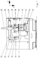
- Figures 1 and 2 show a machining center with a machine bed 10, on which a headstock 12 is slidably mounted in the transverse direction (Y axis) and in the longitudinal direction (Z axis) by means of guides 14.
- the horizontally arranged work spindle 16 is mounted in the headstock 12 with a tool clamping device.
- horizontal guides 20 are mounted in the longitudinal direction above the headstock 12, in which a carriage 22 is mounted so as to be movable in the W direction.
- the carriage 22 is moved by a motor drive, not shown.
- the carrier 22 protrudes horizontally perpendicular from the wall 18 across the entire width of the machine bed 10.
- a carriage 26 is displaceable in horizontal guides 24 of the running support 22 by means of a drive motor (not shown).
- a lifting carriage 28 is mounted in the carriage 26 so that it can move vertically.
- a tool magazine 30 is mounted above and behind the headstock 12 and below the carriage 22, which is arranged partly on a bracket 32 projecting from the wall 18 and partly on an outer wall of the machine housing.
- the tool magazine 30 expediently consists of individual tool cartridges.
- the tools 34 are arranged in the tool magazine with a vertical axis and are held in tool holders 36, which are arranged in rows parallel to the wall 18 (W axis). Between the rows of tool holders 36, lanes 38 remain free, into which the tool changer can enter.
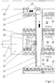
- the carriage 26 with the lifting carriage 28 is shown in more detail in FIGS. 3 and 4.
- the carriage 26 has a frame 40 made of vertical plates.
- the frame 40 is slidably mounted in the guides 24 of the carrier 22.
- the lifting slide 28 is mounted vertically displaceably in the frame 40 by means of roller bearings.
- the lifting slide 28 is designed as a vertical column which can be moved by a stroke which corresponds essentially to the vertical distance between the spindle 16 and the plane of the tool holders 36 of the tool magazine 30.
- An electric motor 42 is attached to the outside of the frame 40.
- the motor 42 drives a drive pulley 44 mounted in the frame 40 with a horizontal axis.
- a Toothed belt 46 is guided around the drive pulley 44 by means of deflection pulleys 48.
- the endlessly rotating toothed belt 46 runs over an upper pulley 50 mounted at the top in the lifting carriage 28 and a lower pulley 52 mounted at the bottom in the lifting carriage 28.
- a locking disk 54 is seated in a rotationally fixed manner on the axis of the upper pulley 50 and has a sector 56 with a larger radius that extends over an angle of 90 °.
- the area of the locking disk 54 with the smaller radius is enclosed over a circumference of 180 ° by a stop part 58 fastened to the lifting slide 28, which forms an upper stop 58a and a lower stop 58b offset by 180 ° for the sector 56 of the locking disk 54.
- the rotational movement of the locking disk 54 and thus the upper pulley 50 is thereby limited to an angle of 90 °.
- a pawl 60 is pivotally mounted on the carriage 28 at the top.
- the pawl 60 is held against the circumference of the locking disk 54 by a pneumatic cylinder 62.
- the pawl 60 can protrude into the locking washer 54 behind the sector 56 when the sector 56 is at the upper stop 58a, as shown in FIG. If the locking pawl 60 has fallen into the locking disc 54 in this way, the locking disc 54 is held between the nose of the locking pawl 60 and the upper stop 58a of the stop part 58, so that the upper pulley 50 is locked against rotation on the lifting slide 28.
- the pawl 60 can be lifted out of the locking disk 54 by means of an idler roller 64 mounted on its free end.
- a side Gripper head 66 attached at the lower end of the lifting carriage 28 at the lower end of the lifting carriage 28 at the lower end of the lifting carriage 28.
- the gripper head 66 is rotatably mounted on the lifting slide 28 by means of a ball bearing 68, its axis of rotation coinciding with the axis of the lower pulley 52.
- An index pin 70 parallel to the axis of rotation of the gripper head 66 is mounted in the gripper head 66 and engages spring-loaded in a bore 72 in the lifting carriage 28 in order to lock the gripper head 66 in a rotationally fixed manner on the lifting carriage 28.
- a pin 76 is inserted vertically into the index pin 70 and protrudes through an elongated hole of the gripper head 66 running in the longitudinal direction of the index pin 70 and on the outside thereof from the gripper head 66 protruding end of a roller 78 is rotatably mounted.
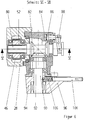
- the lower pulley 52 which is mounted in the lifting carriage by means of ball bearings, is axially penetrated by a spline shaft 80 which is axially displaceable in the lower pulley 52 and is positively entrained in the direction of rotation by this pulley 52.
- the spline shaft 80 axially penetrates the gripper head 66.
- Two bevel gearwheels 82 and 84 are keyed onto the spline shaft 80 in the gripper head 66.
- the bevel gearwheels 82 and 84 are arranged on the spline shaft 80 with a small axial distance and with a point directed towards one another.
- the spline shaft 80 is axially displaceable by means of a fluid cylinder 86 via a pivot lever 88, as shown in FIG. 6.
- a gripper axis 90 is rotatably mounted in the gripper head 66 perpendicular to the spline shaft 80.
- a gripper 94 is seated on the gripper axis 90 with two arms 96 and 98 arranged at right angles to one another and at right angles to the gripper axis 90. As can be seen from FIG.
- the arms 96 and 98 each have two jaws 100 which can be pivoted relative to one another.
- the free front ends of the jaws 100 serve for gripping the tools 34.
- the rear ends of the jaws 100 are each articulated via a lever 102 to a slide 104 which is mounted so as to be radially displaceable in the middle in the arms 96 and 98, respectively.
- the slide 104 is loaded radially outwards by a compression spring 106, so that the levers 102 pivot the jaws 100 towards one another in the closed position in the manner of a toggle lever.
- the jaws 100 are opened against the force of the compression spring 106.
- the slides 104 are supported radially on the inside on the circumference of a disk 108 which is concentric with the gripper axis 90.
- the radius of the disk 108 is selected so that the slides 104 are held in the closed position of the jaws 100, so that the jaws 100 are locked in a form-fitting manner in the closed position.
- the circumference of the disk 108 has depressions 110 each offset by 90 ° from one another. If the gripper 94 comes into an angular position in which the slides 104 enter the recesses 110, the sliders 104 can be moved inwards against the force of the compression spring 106, so that the jaws 100 can be opened.
- a link plate 112 is attached to the underside of the frame 40.
- Two backdrop tracks 114 and 116 are formed in the backdrop plate 112.
- the scenes 114 and 116 lead from an open vertically downward Inlet end upward in a quarter circle, so that its upper end is essentially horizontal, as can be seen most clearly in FIG.
- the two guide tracks 114 and 116 are arranged at right angles to one another in their profile cross section, as can be seen most clearly from FIG. 4.
- the open lower inlet ends of the slide tracks 114 and 116 are arranged such that the slide roller 74 enters the slide track 114 and the roller 78 enters the slide track 116 when the lifting slide 28 moves upward from the position shown in FIGS. 3 and 4.
- the slide track 116 for the roller 78 of the pin 76 has an inlet slope 118, which can be seen in FIG. 4. If the roller 78 runs over the inlet slope 118 when it enters the sliding track 116, it is displaced in the axial direction of the index pin 70 so that the pin 76 lifts the index pin 70 out of the bore 72 against the spring force. As a result, the gripper head 66 is unlocked and rotatable by the lifting slide 28.
- the gripper head 66 is pivoted by 90 ° around the axis of the spline shaft 80 in accordance with the quarter-circle arc of the guide track 114 and 116. This allows the gripper axis 90 to be pivoted between a horizontal position shown in FIGS. 3 and 4 and a vertical position.
- the motor 42 rotates in such a way that the drive pulley 44 rotates clockwise in the illustration in FIG. 3. This would also turn the upper pulley 50 clockwise; however, this rotation is blocked because the locking pulley 54 connected to the upper pulley 50 rests with its sector 56 against the stop 58a, as shown in FIG. Because the upper pulley 50 is blocked, driving the drive pulley 44 clockwise causes the lift carriage 28 to move downward in the frame 40.
- the gripper head 66 assumes the position shown in FIGS. 3 and 4 with the horizontal gripper axis and is locked to the lifting slide 28 by means of the index pin 70.
- the gripper 94 assumes the position shown in FIG. 4, the downward-pointing arm 96 being empty, while the horizontal arm 98 is holding a new tool.
- the empty arm 96 of the gripper 94 When the lifting slide 28 reaches its lowest position, the empty arm 96 of the gripper 94 is pushed onto the machined tool clamped on the spindle 16 and detects it.
- the jaws 100 of the arm 96 can be spread apart against the force of the compression spring 106 in order to grip the tool.
- the tool is then held between the jaws 100 by the force of the compression spring 106, which is translated via the lever 102. Now the headstock 12 is moved backwards in the Z direction, so that the finished tool is lifted out of the spindle 16.
- the motor 42 is now switched over and drives the drive pulley 44 in the counterclockwise direction.
- the toothed belt 46 now takes the upper pulley 50 with it, which can rotate from the position shown in FIG. 3 to the position shown in FIG. 9 by 90 ° until the sector 56 comes into contact with the lower stop 58b.
- the pawl 60 runs on the outer circumference of the sector 56.
- This rotation of the upper pulley 50 by 90 ° corresponds to a rotation of the lower pulley 52 also by 90 °.
- the rotation of the lower pulley 52 by 90 ° drives the gripper axis 90 via the spline shaft 80, the bevel gear 82 and the bevel gear 92 which engages with it, since the gripper head 66 is locked on the lifting slide 28.
- the gripper 94 is thus also pivoted through 90 °, so that the arm 96 with the finished tool is now horizontal and the arm 98 with the new tool 34 is directed downward into the position in front of the spindle 16. Now the headstock 12 is moved forward again so that the new tool 34 is inserted into the spindle 16.
- the gripper 94 pivots, the slides 104 of the arms 96 and 98 run on the circumference of the disk 108, so that the jaws 100 are blocked and the tools 34 fall out of the gripper 94 Swivel movement is excluded.
- the slides 104 again cover the recesses 110, so that the tools 34 are held resiliently in the jaws 100 again.
- the gripper 94 can now be moved upwards, the jaws 100 of the arm 98 being pulled resiliently from the tool 34 held in the spindle 16.
- the motor 42 is further driven in the counterclockwise direction of rotation of the drive pulley 44.
- the locking disk 54 which bears against the lower stop 58b with its sector 56, blocks the upper pulley 50 so that the drive of the drive pulley 44 leads to the lifting carriage 28 being raised.
- the pawl 60 comes free from the ramp slope 122, but is still on the sector 56 of the locking disk 54, as shown in Figure 9.
- the gripper head 66 comes to the link plate 112.
- the roller 78 of the pin 76 runs on the inlet slope 118 of the connecting link 116. This pulls the index pin 70 out of the bore 72 of the lifting carriage 28, so that the gripper head 66 is now freely rotatable relative to the lifting slide 28.
- the link roller 74 of the index pin 70 runs in the curved link path 114, while the roller 78 runs in the parallel link path 116.
- the gripper head 66 is pivoted about its axis coinciding with the spline shaft 80 by 90 ° until it stops at the end of the pivoting movement with the vertical gripper axis 90 when the link roller 74 reaches the horizontal end of the Scenic track 114 has reached.
- the slide roller 74 seated in the horizontal end section of the slide track 114 holds the lifting slide 28 in its upper end position.
- the gripper 94 In the upper end position of the lifting slide 28, the gripper 94 is at the height of the tool holders 36 of the tool magazine 30, its gripper axis 90 being directed vertically downward, and the pivoting plane of the gripper 94 is thus horizontal.
- the empty arm 98 points to the right or to the left, as seen in the W direction, while the arm 96 with the machined tool stands forwards or backwards in the W direction.
- the gripper 94 is now driven in a controlled manner into one of the alleys 38 of the tool magazine 30 until the empty arm 98 reaches the tool holder 36, in which the next tool 34 called up by the control program is stored.
- the selection of the pivoting direction of the gripper 94 by means of the bevel gear wheels 82 and 84 serves to position the empty arm 98 of the gripper 94 already during the upward movement of the lifting carriage 28 so that it is on the tool holders 36 the A-side or the tool holders 36 on the opposite B-side of the alley 38 is directed.
- the gripper 94 is now moved against the selected tool holder 36, with its empty arm 98 gripping the selected new tool.
- the tool 34 is removed from the tool holder 36.
- the motor 42 is turned on again in the direction of rotation so that the drive pulley 44 rotates clockwise.
- the upper pulley 50 can thereby rotate through an angle of 90 ° in the clockwise direction, the sector 56 of the locking disk 54 rotating through 90 ° from the position shown in FIG. 9 and again coming to a stop at the upper stop 58a.
- the pawl 60 can again fall behind the sector 56, so that the upper pulley 50 is blocked again, as shown in Figure 7.
- the gripper 94 is pivoted 90 ° to the right or to the left, so that the arm 96 with the processed tool is now on the Tool holder 36 is directed, from which the new tool was removed.
- the gripper 94 By moving the gripper 94, the processed tool 34 can now be placed in the free tool holder 36.
- the lifting carriage 28 is now moved back into its position above and in front of the spindle 16. The new tool is now ready for the next tool change.
- the lifting slide 28 is moved downwards, for which purpose the motor 42 drives the drive pulley 44 again in the clockwise direction.
- the locking disk 54 is in the in 7 blocked position shown, so that the drive of the toothed belt 46 leads to a downward movement of the lifting carriage 28.
- the link roller 74 again moves downward in the link path 114, as a result of which the gripper head 66 is pivoted again from its position with a vertical gripper axis 90 into its position with a horizontal gripper axis 90.
- the gripper 94 is pivoted about its gripper axis 90 such that the arm 96, which is now empty again, is directed downward and the arm 98 holding the new tool 34 stands horizontally.
- the roller 78 of the pin 76 runs out over the entry slope 118 of the link path 116, so that the index pin 70 is pushed back into the bore 72 by spring force and the gripper head 66 again on the lifting slide 28 is locked.
- the tool changer is now back in the initial state of the cycle described above.
Landscapes
- Engineering & Computer Science (AREA)
- Mechanical Engineering (AREA)
- Automatic Tool Replacement In Machine Tools (AREA)
- Turning (AREA)
Claims (9)
- Changeur d'outils pour centre d'usinage à broche horizontale comportant un magasin d'outilss logeant des outilss de manière verticale, un chariot mobile dans une direction horizontale (axe V) perpendiculaire à la broche, un traîneau mobile sur le chariot dans une direction verticale (axe U), un moteur porté par le chariot et entraînant le traîneau dans la direction verticale (axe U), une tête de préhension pivotante portée par le traîneau et une pince à deux bras montée par l'axe de préhension, de manière pivotante dans la tête de préhension, la pince pouvant se déplacer entre deux positions avec l'outils disposé verticalement et horizontalement,
caractérisé en ce que,
le chariot (26) est mobile dans une direction horizontale (axe W) parallèle à la broche (16), la tête de préhension (36) circule dans un chemin à coulisse (114) du chariot (26) lors du mouvement vertical du traîneau (28) et bascule entre une position avec l'axe de préhension (90) horizontal et une position avec cet axe vertical, le moteur (42) entraînant le traîneau (28) par l'intermédiaire d'un moyen de traction circulant sans fin (44, 46, 50, 52) et le moyen de traction (46, 50, 52) commutable entraînant le mouvement de basculement de la pince (94) autour de son axe de préhension (90). - Changeur d'outils selon la revendication 1, caractérisé en ce que les bras (96, 98) de la pince (94) sont perpendiculaires entre eux et par rapport à l'axe de préhension (90).
- Changeur d'outils selon la revendication 1 ou 2, caractérisé en ce que la tête de préhension (66) est fixée par un verrouillage au traîneau (28) et ce verrouillage peut s'ouvrir pour permettre à la tête de préhension (66) de basculer.
- Changeur d'outils selon la revendication 3, caractérisé en ce que le verrouillage comporte une broche d'indexage (70) prévue dans la tête de préhension (66), cette broche pénétrant dans le traîneau (28) et lors du mouvement de soulèvement du traîneau (28) cette broche est dégagée du traîneau (28) par une rampe d'entrée (118).
- Changeur d'outils selon la revendication 1, caractérisé en ce que les moyens de traction comprennent une courroie crantée (46) passant sur une poulie à courroie supérieure (50) et une poulie à courroie inférieure (52) du traîneau (28).
- Changeur d'outils selon la revendication 5, caractérisé en ce que l'une des poulies à courroie (50) peut se bloquer pour entraîner le traîneau (28) à l'aide de la courroie crantée (46) et peut commuter sur un angle de pivotement limité pour que lorsque le traîneau (28) est fixe, pouvoir entraîner le mouvement de pivotement de la pince (94).
- Changeur d'outils selon la revendication 6, caractérisé en ce que la pince (94) est entraînée à l'aide d'une roue conique dentée (92) portée par son axe de préhension (90), cette roue dentée étant en prise avec une roue dentée conique (82) solidaire en rotation de l'une des poulies à courroie (52).
- Changeur d'outils selon la revendication 7, caractérisé en ce qu'un arbre cannelé (80) est relié solidairement en rotation mais coulissant axialement à la poulie à courroie (52) et cet arbre cannelé (80) porte solidairement deux roues coniques dentées (82 et 84) écartées axialement, dont les sommets sont dirigés l'un vers l'autre, ces roues dentées arrivant en prise, sélectivement par coulissement axial de l'arbre cannelé (80) avec la roue dentée conique (92) de l'axe de préhension (90) pour choisir le sens de pivotement de la pince (94).
- Changeur d'outils selon l'une des revendications précédentes, caractérisé en ce que le magasin à outilss (30) est situé dans un plan horizontal au-dessus de la broche (16) et se compose de logements à outilss (36) répartis en rangées parallèles par rapport à l'axe de la broche (16), rangées entre lesquelles subsistent des couloirs (38) pour le passage de la pince (94).
Applications Claiming Priority (2)
| Application Number | Priority Date | Filing Date | Title |
|---|---|---|---|
| DE4331064 | 1993-09-13 | ||
| DE4331064A DE4331064A1 (de) | 1993-09-13 | 1993-09-13 | Werkzeugwechsler für ein Bearbeitungszentrum |
Publications (2)
| Publication Number | Publication Date |
|---|---|
| EP0642880A1 EP0642880A1 (fr) | 1995-03-15 |
| EP0642880B1 true EP0642880B1 (fr) | 1996-04-17 |
Family
ID=6497606
Family Applications (1)
| Application Number | Title | Priority Date | Filing Date |
|---|---|---|---|
| EP94113872A Expired - Lifetime EP0642880B1 (fr) | 1993-09-13 | 1994-09-05 | Changeur d'outil pour un centre d'usinage |
Country Status (4)
| Country | Link |
|---|---|
| US (1) | US5496249A (fr) |
| EP (1) | EP0642880B1 (fr) |
| AT (1) | ATE136835T1 (fr) |
| DE (2) | DE4331064A1 (fr) |
Families Citing this family (17)
| Publication number | Priority date | Publication date | Assignee | Title |
|---|---|---|---|---|
| DE10012665C2 (de) * | 2000-03-15 | 2003-10-09 | Deckel Maho Seebach Gmbh | Werkzeugwechselvorrichtung für eine Werkzeugmaschine |
| DE10337547A1 (de) * | 2003-08-05 | 2005-03-03 | Ex-Cell-O Gmbh | Werkzeugwechselvorrichtung für eine Werkzeugmaschine und Verfahren zum Werkzeugwechsel an einer Werkzeugmaschine |
| DE102004061060A1 (de) * | 2004-12-18 | 2006-07-06 | Bosch Rexroth Ag | Werkzeugwechselvorrichtung und Werkzeugwechselverfahren |
| DE102005006722A1 (de) * | 2005-02-07 | 2006-08-10 | Index-Werke Gmbh & Co. Kg Hahn & Tessky | Werkstückbearbeitungsanlage |
| DE102005057174A1 (de) * | 2005-11-30 | 2007-05-31 | Siemens Ag | Maschine mit einer mechanischen Führung zur Führung der Bewegung einer ersten und einer zweiten Vorrichtung |
| US8822934B2 (en) * | 2006-11-03 | 2014-09-02 | Accuray Incorporated | Collimator changer |
| KR100819434B1 (ko) * | 2007-03-29 | 2008-04-08 | 김성철 | 머시닝센터의 자동 공구교환장치 |
| DE102007017324B4 (de) | 2007-04-11 | 2009-08-20 | Starragheckert Gmbh | Einrichtung zum Wechseln von Werkzeugen und/oder Werkstücken |
| JP6136119B2 (ja) * | 2012-01-30 | 2017-05-31 | ブラザー工業株式会社 | 工作機械 |
| TW201529220A (zh) * | 2013-10-31 | 2015-08-01 | Anca Pty Ltd | 工具夾持裝置 |
| CN105873720B (zh) | 2014-09-03 | 2017-05-10 | 山崎马扎克公司 | 刀库 |
| EP3135428B1 (fr) | 2014-09-05 | 2018-10-24 | Yamazaki Mazak Corporation | Magasin d'outils et dispositif de changement d'outil |
| DE102015004840A1 (de) | 2015-04-15 | 2016-10-20 | Vollmer Werke Maschinenfabrik Gmbh | Vorrichtung zum Einsetzen von Werkstücken oder Werkzeugen in eine Werkzeugmaschine |
| CN112173707A (zh) * | 2020-10-15 | 2021-01-05 | 上海富驰高科技股份有限公司 | 一种两孔摄像头头圈整形模具用搬运装置 |
| CN113275918B (zh) * | 2021-04-30 | 2024-11-29 | 武汉楚凯汽车零部件有限公司 | 一种后上控制臂双联加工工装 |
| CN115747886B (zh) * | 2022-12-13 | 2024-09-24 | 兰州理工大学 | 一种铝电解多功能天车末端作业工具的快速连接更换机构 |
| EP4545248B1 (fr) * | 2023-10-26 | 2026-02-18 | Sanjet International Co., Ltd. | Dispositif de changement d'outil pour machine d'usinage |
Family Cites Families (19)
| Publication number | Priority date | Publication date | Assignee | Title |
|---|---|---|---|---|
| US3822466A (en) * | 1972-03-14 | 1974-07-09 | Mitsubishi Heavy Ind Ltd | Automatic tool exchanger for large-scaled floor-type horizontal boring machines |
| CH597978A5 (fr) * | 1976-04-07 | 1978-04-14 | Dixie Sa Usine 2 | |
| DE3017613A1 (de) * | 1980-05-08 | 1981-11-12 | Burkhardt & Weber GmbH & Co KG, 7410 Reutlingen | Werkzeugwechselvorrichtung fuer eine werkzeugmaschine |
| JPS5754044A (ja) * | 1980-09-03 | 1982-03-31 | Hitachi Seiko Ltd | Jidokogukokansochi |
| JPS58137538A (ja) * | 1982-02-09 | 1983-08-16 | Toshiba Mach Co Ltd | 自動工具交換装置 |
| JPS5934935U (ja) * | 1982-08-30 | 1984-03-05 | 株式会社大隈鐵工所 | アタツチメントの自動工具交換装置 |
| DE3408734A1 (de) * | 1984-03-09 | 1985-09-19 | Friedrich Deckel AG, 8000 München | Einrichtung zum einwechseln von werkzeugen oder dgl. in die arbeitsspindel einer werkzeugmaschine |
| US4654957A (en) * | 1984-06-22 | 1987-04-07 | Ex-Cell-O Corporation | Flexible machining apparatus with single shank tool and multi-spindle tool head changing and operating capabilities |
| US4599786A (en) * | 1984-09-04 | 1986-07-15 | Cincinnati Milacron Inc. | Grinding machine with apparatus for changing grinding wheel tools and workpieces |
| DD237807A1 (de) * | 1985-05-31 | 1986-07-30 | Mikromat Dresden Betrieb | Einrichtung fuer den automatischen werkzeugwechsel an werkzeugmaschinen |
| JPS62188641A (ja) * | 1986-02-13 | 1987-08-18 | Kitamura Kikai Kk | 自動工具交換方法およびその装置 |
| DE3636498A1 (de) * | 1986-10-27 | 1988-05-05 | Maho Werkzeugmaschbau Babel | Werkzeugwechsler fuer programmgesteuerte universal-fraes- und bohrmaschinen |
| DE3883812D1 (de) * | 1987-03-11 | 1993-10-14 | Doerries Scharmann Gmbh | Flexibles Fertigungssystem für spanabhebende Werkstückbearbeitung. |
| DE3714125A1 (de) * | 1987-04-28 | 1988-11-10 | Heinhaus Matthias Dipl Ing Fh | Automatische werkzeugwechseleinrichtung fuer universalbearbeitungsmaschinen |
| DE3731280A1 (de) * | 1987-09-17 | 1989-03-30 | Maho Ag | Werkzeugwechsler fuer universal-fraes- und bohrmaschinen |
| DE3733064A1 (de) * | 1987-09-30 | 1989-04-13 | Wanderer Maschinen Gmbh | Werkzeugwechselsystem |
| DE8905795U1 (de) * | 1989-05-09 | 1989-07-20 | MAHO AG, 8962 Pfronten | Werkzeugwechsler für programmgesteuerte Werkzeugmaschinen |
| DE3925567A1 (de) * | 1989-08-02 | 1991-02-07 | Werner & Kolb Werkzeugmasch | Handhabungsgeraet fuer bearbeitungszentren der spanabhebenden fertigung |
| DE4009537A1 (de) * | 1990-03-24 | 1991-10-02 | Werner & Kolb Werkzeugmasch | Werkzeugwechseleinrichtung fuer eine bearbeitungsmaschine |
-
1993
- 1993-09-13 DE DE4331064A patent/DE4331064A1/de not_active Withdrawn
-
1994
- 1994-09-05 AT AT94113872T patent/ATE136835T1/de not_active IP Right Cessation
- 1994-09-05 EP EP94113872A patent/EP0642880B1/fr not_active Expired - Lifetime
- 1994-09-05 DE DE59400210T patent/DE59400210D1/de not_active Expired - Fee Related
- 1994-09-12 US US08/304,305 patent/US5496249A/en not_active Expired - Fee Related
Also Published As
| Publication number | Publication date |
|---|---|
| EP0642880A1 (fr) | 1995-03-15 |
| DE4331064A1 (de) | 1995-03-16 |
| DE59400210D1 (de) | 1996-05-23 |
| ATE136835T1 (de) | 1996-05-15 |
| US5496249A (en) | 1996-03-05 |
Similar Documents
| Publication | Publication Date | Title |
|---|---|---|
| EP1982799B1 (fr) | Agencement de manipulation | |
| DE2325629C2 (de) | Werkzeugmagazin für eine Werkzeugmaschine | |
| DE3609086C2 (fr) | ||
| EP0642880A1 (fr) | Changeur d'outil pour un centre d'usinage | |
| DE19739265A1 (de) | Vorrichtung zum doppelseitigen Schleifen von flachen, scheibenförmigen Werkstücken | |
| DE3686476T2 (de) | Palettenwechseleinrichtung fuer eine werkzeugmaschine. | |
| DE2540979C2 (de) | Automatische Werkzeugwechselvorrichtung für eine Vertikal- oder Karusselldrehmaschine | |
| DE2444124C3 (de) | Zusatzeinrichtung zum automatischen Be- und/oder Entladen von Werkzeugmaschinen | |
| DE68920667T2 (de) | Automatischer Palettenwechsler. | |
| DE60113627T2 (de) | Werkzeugmaschine und Palettenwechsler dafür | |
| DE3134833C2 (de) | Palettenwechseleinrichtung bei einer numerisch gesteuerten Werkzeugmaschine | |
| DE3505138A1 (de) | Mehrfach-bearbeitungsmaschine mit werkzeug- und werkstueckwechseleinrichtung | |
| DE60007248T2 (de) | Werkzeugtransfervorrichtung für Werkzeugmaschinen | |
| DE2847683A1 (de) | Automatische werkzeugwechselvorrichtung fuer eine werkzeugmaschine | |
| DE4136916C2 (de) | Mehrspindel-Drehmaschine | |
| DE2416474A1 (de) | Werkzeugmaschine | |
| EP0642397A1 (fr) | Tour a deux broches porte-pieces | |
| EP1651381B1 (fr) | Machine-outil avec systeme de fixation des deux cotes | |
| DE3331771C2 (fr) | ||
| EP1194266B1 (fr) | Dispositif de changement d'outil destine a une machine-outil | |
| EP0157950B1 (fr) | Machine-outil avec une poupée mobile suivant plusieurs axes | |
| DE3115481C2 (de) | Werkstückpaletten-Speicher für ein Bearbeitungszentrum | |
| DE3913137C2 (fr) | ||
| DE4330915C1 (de) | Palettenwechsler für Werkzeugmaschinen | |
| DE3907687C2 (de) | Stanzmaschine |
Legal Events
| Date | Code | Title | Description |
|---|---|---|---|
| PUAI | Public reference made under article 153(3) epc to a published international application that has entered the european phase |
Free format text: ORIGINAL CODE: 0009012 |
|
| AK | Designated contracting states |
Kind code of ref document: A1 Designated state(s): AT BE CH DE ES FR GB IT LI LU NL SE |
|
| 17P | Request for examination filed |
Effective date: 19950511 |
|
| 17Q | First examination report despatched |
Effective date: 19950718 |
|
| GRAH | Despatch of communication of intention to grant a patent |
Free format text: ORIGINAL CODE: EPIDOS IGRA |
|
| GRAA | (expected) grant |
Free format text: ORIGINAL CODE: 0009210 |
|
| AK | Designated contracting states |
Kind code of ref document: B1 Designated state(s): AT BE CH DE ES FR GB IT LI LU NL SE |
|
| PG25 | Lapsed in a contracting state [announced via postgrant information from national office to epo] |
Ref country code: NL Free format text: LAPSE BECAUSE OF FAILURE TO SUBMIT A TRANSLATION OF THE DESCRIPTION OR TO PAY THE FEE WITHIN THE PRESCRIBED TIME-LIMIT Effective date: 19960417 Ref country code: IT Free format text: LAPSE BECAUSE OF FAILURE TO SUBMIT A TRANSLATION OF THE DESCRIPTION OR TO PAY THE FEE WITHIN THE PRE;WARNING: LAPSES OF ITALIAN PATENTS WITH EFFECTIVE DATE BEFORE 2007 MAY HAVE OCCURRED AT ANY TIME BEFORE 2007. THE CORRECT EFFECTIVE DATE MAY BE DIFFERENT FROM THE ONE RECORDED.SCRIBED TIME-LIMIT Effective date: 19960417 Ref country code: ES Free format text: THE PATENT HAS BEEN ANNULLED BY A DECISION OF A NATIONAL AUTHORITY Effective date: 19960417 Ref country code: BE Effective date: 19960417 |
|
| REF | Corresponds to: |
Ref document number: 136835 Country of ref document: AT Date of ref document: 19960515 Kind code of ref document: T |
|
| ET | Fr: translation filed | ||
| REF | Corresponds to: |
Ref document number: 59400210 Country of ref document: DE Date of ref document: 19960523 |
|
| GBT | Gb: translation of ep patent filed (gb section 77(6)(a)/1977) |
Effective date: 19960529 |
|
| PG25 | Lapsed in a contracting state [announced via postgrant information from national office to epo] |
Ref country code: SE Effective date: 19960717 |
|
| PG25 | Lapsed in a contracting state [announced via postgrant information from national office to epo] |
Ref country code: AT Effective date: 19960905 |
|
| PG25 | Lapsed in a contracting state [announced via postgrant information from national office to epo] |
Ref country code: LU Free format text: LAPSE BECAUSE OF NON-PAYMENT OF DUE FEES Effective date: 19960930 Ref country code: LI Effective date: 19960930 Ref country code: CH Effective date: 19960930 |
|
| NLV1 | Nl: lapsed or annulled due to failure to fulfill the requirements of art. 29p and 29m of the patents act | ||
| PLBE | No opposition filed within time limit |
Free format text: ORIGINAL CODE: 0009261 |
|
| STAA | Information on the status of an ep patent application or granted ep patent |
Free format text: STATUS: NO OPPOSITION FILED WITHIN TIME LIMIT |
|
| 26N | No opposition filed | ||
| REG | Reference to a national code |
Ref country code: CH Ref legal event code: PL |
|
| PGFP | Annual fee paid to national office [announced via postgrant information from national office to epo] |
Ref country code: GB Payment date: 19980827 Year of fee payment: 5 |
|
| PGFP | Annual fee paid to national office [announced via postgrant information from national office to epo] |
Ref country code: FR Payment date: 19980917 Year of fee payment: 5 |
|
| PGFP | Annual fee paid to national office [announced via postgrant information from national office to epo] |
Ref country code: DE Payment date: 19981029 Year of fee payment: 5 |
|
| PG25 | Lapsed in a contracting state [announced via postgrant information from national office to epo] |
Ref country code: GB Free format text: LAPSE BECAUSE OF NON-PAYMENT OF DUE FEES Effective date: 19990905 |
|
| GBPC | Gb: european patent ceased through non-payment of renewal fee |
Effective date: 19990905 |
|
| PG25 | Lapsed in a contracting state [announced via postgrant information from national office to epo] |
Ref country code: FR Free format text: LAPSE BECAUSE OF NON-PAYMENT OF DUE FEES Effective date: 20000531 |
|
| PG25 | Lapsed in a contracting state [announced via postgrant information from national office to epo] |
Ref country code: DE Free format text: LAPSE BECAUSE OF NON-PAYMENT OF DUE FEES Effective date: 20000701 |
|
| REG | Reference to a national code |
Ref country code: FR Ref legal event code: ST |