EP0642894B2 - Kontinuierliches Rotationsverfahren zur dreidimensionalen Formgestaltung der Oberfläche von Polstern als Schaumstoff - Google Patents
Kontinuierliches Rotationsverfahren zur dreidimensionalen Formgestaltung der Oberfläche von Polstern als Schaumstoff Download PDFInfo
- Publication number
- EP0642894B2 EP0642894B2 EP94202656A EP94202656A EP0642894B2 EP 0642894 B2 EP0642894 B2 EP 0642894B2 EP 94202656 A EP94202656 A EP 94202656A EP 94202656 A EP94202656 A EP 94202656A EP 0642894 B2 EP0642894 B2 EP 0642894B2
- Authority
- EP
- European Patent Office
- Prior art keywords
- die
- portions
- foam
- slab
- depressions
- Prior art date
- Legal status (The legal status is an assumption and is not a legal conclusion. Google has not performed a legal analysis and makes no representation as to the accuracy of the status listed.)
- Expired - Lifetime
Links
- 239000006260 foam Substances 0.000 title claims abstract description 81
- 238000000034 method Methods 0.000 title claims abstract description 29
- 230000008569 process Effects 0.000 title abstract description 5
- 238000007493 shaping process Methods 0.000 title description 3
- 238000005520 cutting process Methods 0.000 claims abstract description 15
- 238000003825 pressing Methods 0.000 claims abstract description 4
- 230000007704 transition Effects 0.000 claims description 11
- 238000004519 manufacturing process Methods 0.000 description 7
- 210000003484 anatomy Anatomy 0.000 description 4
- 239000006261 foam material Substances 0.000 description 4
- 210000001519 tissue Anatomy 0.000 description 4
- 230000008901 benefit Effects 0.000 description 3
- 230000017531 blood circulation Effects 0.000 description 3
- 239000000463 material Substances 0.000 description 3
- 230000009286 beneficial effect Effects 0.000 description 2
- 230000006835 compression Effects 0.000 description 2
- 238000007906 compression Methods 0.000 description 2
- 230000001419 dependent effect Effects 0.000 description 2
- 238000009826 distribution Methods 0.000 description 2
- 230000001788 irregular Effects 0.000 description 2
- 239000000243 solution Substances 0.000 description 2
- 238000009423 ventilation Methods 0.000 description 2
- 206010040943 Skin Ulcer Diseases 0.000 description 1
- 230000009471 action Effects 0.000 description 1
- 230000008859 change Effects 0.000 description 1
- 230000004087 circulation Effects 0.000 description 1
- 230000000295 complement effect Effects 0.000 description 1
- 230000001627 detrimental effect Effects 0.000 description 1
- 230000003292 diminished effect Effects 0.000 description 1
- 230000008030 elimination Effects 0.000 description 1
- 238000003379 elimination reaction Methods 0.000 description 1
- 230000008570 general process Effects 0.000 description 1
- 230000035876 healing Effects 0.000 description 1
- 238000002347 injection Methods 0.000 description 1
- 239000007924 injection Substances 0.000 description 1
- 238000003754 machining Methods 0.000 description 1
- 230000000284 resting effect Effects 0.000 description 1
- 210000004872 soft tissue Anatomy 0.000 description 1
- 239000007787 solid Substances 0.000 description 1
Images


Classifications
-
- A—HUMAN NECESSITIES
- A61—MEDICAL OR VETERINARY SCIENCE; HYGIENE
- A61G—TRANSPORT, PERSONAL CONVEYANCES, OR ACCOMMODATION SPECIALLY ADAPTED FOR PATIENTS OR DISABLED PERSONS; OPERATING TABLES OR CHAIRS; CHAIRS FOR DENTISTRY; FUNERAL DEVICES
- A61G7/00—Beds specially adapted for nursing; Devices for lifting patients or disabled persons
- A61G7/05—Parts, details or accessories of beds
- A61G7/057—Arrangements for preventing bed-sores or for supporting patients with burns, e.g. mattresses specially adapted therefor
- A61G7/05707—Arrangements for preventing bed-sores or for supporting patients with burns, e.g. mattresses specially adapted therefor with integral, body-bearing projections or protuberances
-
- B—PERFORMING OPERATIONS; TRANSPORTING
- B26—HAND CUTTING TOOLS; CUTTING; SEVERING
- B26D—CUTTING; DETAILS COMMON TO MACHINES FOR PERFORATING, PUNCHING, CUTTING-OUT, STAMPING-OUT OR SEVERING
- B26D3/00—Cutting work characterised by the nature of the cut made; Apparatus therefor
- B26D3/28—Splitting layers from work; Mutually separating layers by cutting
- B26D3/281—Splitting layers from work; Mutually separating layers by cutting the work being simultaneously deformed by the application of pressure to obtain profiled workpieces
-
- B—PERFORMING OPERATIONS; TRANSPORTING
- B29—WORKING OF PLASTICS; WORKING OF SUBSTANCES IN A PLASTIC STATE IN GENERAL
- B29C—SHAPING OR JOINING OF PLASTICS; SHAPING OF MATERIAL IN A PLASTIC STATE, NOT OTHERWISE PROVIDED FOR; AFTER-TREATMENT OF THE SHAPED PRODUCTS, e.g. REPAIRING
- B29C44/00—Shaping by internal pressure generated in the material, e.g. swelling or foaming ; Producing porous or cellular expanded plastics articles
- B29C44/34—Auxiliary operations
- B29C44/56—After-treatment of articles, e.g. for altering the shape
- B29C44/5627—After-treatment of articles, e.g. for altering the shape by mechanical deformation, e.g. crushing, embossing, stretching
- B29C44/5654—Subdividing foamed articles to obtain particular surface properties, e.g. on multiple modules
-
- Y—GENERAL TAGGING OF NEW TECHNOLOGICAL DEVELOPMENTS; GENERAL TAGGING OF CROSS-SECTIONAL TECHNOLOGIES SPANNING OVER SEVERAL SECTIONS OF THE IPC; TECHNICAL SUBJECTS COVERED BY FORMER USPC CROSS-REFERENCE ART COLLECTIONS [XRACs] AND DIGESTS
- Y10—TECHNICAL SUBJECTS COVERED BY FORMER USPC
- Y10S—TECHNICAL SUBJECTS COVERED BY FORMER USPC CROSS-REFERENCE ART COLLECTIONS [XRACs] AND DIGESTS
- Y10S264/00—Plastic and nonmetallic article shaping or treating: processes
- Y10S264/82—Embossing by foaming
-
- Y—GENERAL TAGGING OF NEW TECHNOLOGICAL DEVELOPMENTS; GENERAL TAGGING OF CROSS-SECTIONAL TECHNOLOGIES SPANNING OVER SEVERAL SECTIONS OF THE IPC; TECHNICAL SUBJECTS COVERED BY FORMER USPC CROSS-REFERENCE ART COLLECTIONS [XRACs] AND DIGESTS
- Y10—TECHNICAL SUBJECTS COVERED BY FORMER USPC
- Y10T—TECHNICAL SUBJECTS COVERED BY FORMER US CLASSIFICATION
- Y10T83/00—Cutting
- Y10T83/04—Processes
- Y10T83/0405—With preparatory or simultaneous ancillary treatment of work
- Y10T83/0419—By distorting within elastic limit
- Y10T83/0429—By compressing
-
- Y—GENERAL TAGGING OF NEW TECHNOLOGICAL DEVELOPMENTS; GENERAL TAGGING OF CROSS-SECTIONAL TECHNOLOGIES SPANNING OVER SEVERAL SECTIONS OF THE IPC; TECHNICAL SUBJECTS COVERED BY FORMER USPC CROSS-REFERENCE ART COLLECTIONS [XRACs] AND DIGESTS
- Y10—TECHNICAL SUBJECTS COVERED BY FORMER USPC
- Y10T—TECHNICAL SUBJECTS COVERED BY FORMER US CLASSIFICATION
- Y10T83/00—Cutting
- Y10T83/343—With means to deform work temporarily
Definitions
- the present invention in the first place relates to a method for making an article of synthetic foam having a three-dimensionally shaped surface with raised portions separated by depressions, comprising the steps of:
- Synthetic foam has been widely used to make mattress overlay pads and similar articles intended to cushion the body of a person resting on a supporting surface.
- such pads seek to provide controlled support by conforming to the natural contours of the user's anatomy so as to avoid areas of concentrated pressure. These areas diminish the user's comfort, and if allowed to persist, the diminished blood flow through the affected tissues frequently leads to painful and slow healing skin ulcerations, which are particularly common among the bed ridden and persons confined to a wheel chair.
- the object of the present invention is to provide a method for making an article of synthetic foam having a three-dimensionally shaped surface with raised portions separated by depressions closely conforming to the geometry of the die surface.
- the present invention provides a method for making an article of synthetic foam having a three-dimensionally shaped surface with raised portions separated by depressions according to claim 1.
- DE-OS-20 50 845 a slab of foam is pressed into depressions in a first roller by a second roller with a planar surface.
- the synthetic foam material is not in direct contact with the die surface, but a conveyor belt is positioned between the foam slab and the die surface.
- line 10 it Is described that accurate three dimensional cutting of foam material between rotating die rollers, in direct contact therewith, is believed impossible.
- DE-OS 33 10 921 teaching a method and a device for providing the surface of articles of deformable material with a three dimensionally shaped surface. Instead of depressions in a die as with the method according to the present invention, a driven endless cutting mask with two-dimensionally shaped apertures is used.
- an existing surface of the foam slab is shaped to a three dimensional geometry by selective removal of foam portions on the existing surface.
- This method is therefore also distinct from convoluting processes which form entirely new convoluted foam surfaces by slicing a foam slab in half to simultaneously make two convoluted pads.
- the cutting is along a plane substantially tangent to said imaginary outer cylindrical surface.
- the raised portions of the die surface may have planar top surfaces which lie tangent to an imaginary roller circumference.
- the planar top surfaces may have radiused edges for a smooth transition between the top surface and the side surfaces of the raised portions.
- the raised portions of the shaped foam surface made according to this invention may have any arbitrary shape as seen in top plan view, and in particular may have regular or irregular polyhedral prismatic shapes with any number of sides.
- the raised elements of the die surface may be straight hexagonal prisms each ending in a flat end surface with a radiused transition between the six sides of the prism and the flat end surface.
- the combined die surface area occupied by the raised portions may be much greater than the combined die surface area occupied by the depressions. This permits the manufacture of three dimensionally shaped surfaces with raised portions having wide planar end surfaces separated by relative narrow depressions in the pad surface. This geometry maximizes the distribution of supporting force against the body of the patient and improves the resistance of the raised portions against excessive flattening, while preserving independent sprig action between adjacent raised portions as well as providing for air circulation and ventilation between the raised portions.
- the raised die portions are polyhedrally shaped.
- the raised portions of the die surface have substantially planar end surfaces generally transverse to a radius of said cylinder.
- the raised portions of the die may have planar top surfaces with radiused edges for producing raised portions with planar top surfaces and radiused edges on said shaped surface.
- the raised portions of the die surface have side surfaces extending from a common bottom surface and a concavely curved transition between said side surfaces, and said bottom surface and the shaped foam surface has radiused lower edges between side surfaces and a bottom surface.
- the raised die portions occupy a combined die surface area substantially unequal to a combined die surface area occupied by said die depressions.
- the raised portions occupy a combined die surface area much greater than a combined die surface area occupied by said depressions.
- said method further comprises the step of turning over the slab after said slicing step and repeating said pressing and cutting steps to shape an opposite surface of the slab.
- Foam portions which are compressed into the slab by the raised portions of the die surface are not significantly cut.
- the uncut foam portions are released from compression and spring up to form the raised portions of the shaped surface of the foam pad, these raised portions being separated by depressions formed by slicing away the extruded foam portions.
- the finished, shaped foam surface is substantially a mirror image of the die surface geometry laid out on the initially flat surface of the foam slab.
- the raised die portions are right prisms having an arbitrary number of sides.
- Said raised die portions are advantageously right prisms arranged radially on said die roller.
- the raised die portions have convexly curved upper portions.
- the raised portions having concavely curved lower portions.
- the raised portions occupy a combined area of the die surface substantially unequal to a combined area of said die surface occupied by the depressions.
- the raised portions occupy a combined area of said die surface much greater than a combined area of the die surface occupied by said depressions.
- Figure 1 is a longitudinal view illustrating the prior art manufacture of convoluted foam pads.
- a rectangular slab of synthetic foam S is fed from left to right in the drawing between two convoluter rollers R1 and R2 which are driven for rotation in opposite senses as indicated by the arrows.
- the two rollers are mounted with their axes parallel to each other and spaced apart so that a gap exists between the outer circumference of the two rollers, which gap is considerably smaller than the thickness of foam slab S.
- the slab is therefore compressed between the rollers and as the slab emerges from the rollers, it is sliced at mid-thickness into two convoluted foam pads P1 and P2 by a cutting blade B which are separated by a spreader D.
- Each roller R1 and R2 has radial projections which can take a variety of geometric shapes, and the arrangement of these radial projections on each roller can take a variety of regular or irregular patterns.
- the radial projections compress portions of the foam slab S, while other portions of the slab passing between the radial projections are not compressed.
- two mutually complementary convoluted surfaces C1 and C2 result on the two foam pads P1 and P2.
- This general process and the convoluter machinery used for this purpose are known and in wide use.
- the convoluted surfaces C1 and C2 of the resulting foam pads suffer from certain limitations and shortcomings.
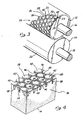
- FIG 2 illustrates the method of three dimensionally shaping an existing surface of a blank foam pad slab according to this invention in a rotary machine which is generally designated by the numeral 10.
- the machine 10 has a roller assembly which includes a die roller 12 and a pressure roller 14.
- This roller assembly is better seen in Figure 3 , where the rollers 12, 14 are seen to be mounted on parallel rotary shafts 16, 18 respectively.
- the shafts are supported in an appropriate machine frame and at least one of the two shafts is driven for rotation by a suitable motor drive, not shown in the drawings.
- the two shafts 16, 18 are spaced apart so that a gap exists between the outer circumference of the die cylinder 12 and the surface of the pressure roller 14, which gap is substantially smaller than the thickness of a synthetic foam slab 20.
- the die roller has a die surface generally designated by numeral 24 which in the illustrated example is comprised of raised portions or die elements 28 with planar hexagonal end surfaces 26 arranged in a honeycomblike regular pattern such that each element 28 is spaced from six adjacent similar elements 28 by a slot recess 30 of constant width between each of the six sides 23 of the hexagonal element. That is, each side 23 of the hexagonal element 28 is parallel to and spaced from a side 23 of an adjacent hexagonal element 28.
- the die surface 24 of the roller 12 can be constructed either by machining a solid cylindrical roller body, as shown in Figure 3 , or by axially assembling a number of die rings 60 on the roller shaft 16' as shown in Figure 7 , each such die ring 60 carrying one circumferential row of die elements 28.
- the spacing between the rollers 12, 14 is such as to force the upper surface 26 of the foam slab 20 against the die surface 24 with sufficient force to extrude foam portions 25 into the depressions 30, while portions 27 of the foam surface 17 underlying the flat end surfaces 26 are compressed between the end surfaces and the pressure roller 14.
- the slab 20 advances against a cutting edge 34 which is positioned between the rollers 12, 14 in a cutting plane tangent to the imaginary outer cylindrical surface 24 so as to slice through the advancing foam slab 20 and cut away those portions 25 of foam extruding into the depressions 30 between the die elements 28, while sparing the foam portions 27 compressed by the end surfaces 26.
- the foam slab 20 is cut in this fashion to produce a support pad 36 with a three-dimensionally shaped support surface 38, and a scrap sheet 39 which consists of the foam material extruded into the slots 30 and cut away from the slab 20.
- the scrap sheet 39 in this example is an open hexagonal mesh consisting of the material removed to make the recesses 50 and has a thickness equal to the depth of the recesses 50 in the pad 36.
- Figure 4 shows one corner of the shaped support surface 38 of the pad 36 obtained by the method illustrated in Figure 2 .
- the three-dimensionally shaped surface 38 is substantially a mirror image of the die surface 24 on the roller 12, and includes raised support elements 40 which are hexagonal right angle prisms perpendicular to the flat bottom or undersurface 15 of the pad 36.
- Each support element 40 has a planar top surface 42, bounded by six side edges 44 and six vertical sides 46 extending between the end surface 42 and a slot bottom 48.
- the slot bottom surface 48 is generally planar and parallel to the underside 15 of the foam pad 36, and defines a common bottom for the depressions 50 which separate the individual support elements 40.
- the depressions 50 collectively define a hexagonal grid, i.e. a network consisting of hexagonal slots joined side to side over the entire shaped surface 38 of the support pad 36.
- the fraction of the shaped support surface 38 occupied by the end surfaces 42 of the support elements 40 is much greater than the fraction occupied collectively by the slots 50, i.e. by the total area of the bottom surface 48.
- This unequal proportion is beneficial in that the weight of the users body is distributed over a relatively large support surface, i.e. the end surfaces 42, while the relatively narrow slots 50 provide sufficient ventilation between the individual support elements 40 to dissipate excessive humidity and heat.
- the support elements 40 are free to respond and adapt individually to the localized pressure and contour of the user's anatomy contacting each support element.
- a particular advantage of the presently disclosed method for making foam pads with three-dimensionally shaped support surfaces is that the ratio of effective support surface (the collective area of end surfaces 42) to the pad area collectively occupied by the recesses 50, is continuously variable through a wide range and dependent only on the choice of geometry of the die surface 24.
- Arbitrary geometric shapes of both the raised support elements 40 as well as the recessed areas 50 of the pad 36 are readily obtainable by suitable configuration of the die surface 24.
- the geometry of the recessed areas 50 is not necessarily dependent upon the geometry of the raised support elements 40.
- Such control over the ratio of support surface to recessed area on a support pad has not been previously possible by manufacture any known continuous rotary process such as convoluter machines, and therefore resort had to be made to either injection forming or pattern sawing of the foam pad.
- the convoluted pad surfaces C1 and C2 only generally follow the geometry of the convoluter rollers R1 and R2, because of the relatively thick layer of foam, i.e. half the thickness of the foam slab S, interposed between the plane of the cutting blade B and the two convoluter rollers.
- This arrangement significantly limits the geometries of the convoluted surfaces obtainable by the prior art method.
- the contouring of the raised elements on the convoluter rollers tends to be smoothed and rounded off by the thickness of foam intervening between the blade B and the rollers.
- the method of this invention permits fabrication of more finely detailed and precisely formed three dimensional support surfaces 38 with clean, sharp geometric features and edges.
- the shaped pad surfaces made according to this invention closely conform to the geometry of the die surface, and small support elements such as hexagons 1/4 inch (6,35 mm) on each side and 1/8 inch high (3,175 mm), separated by 1/16th inch (1,59 mm) wide, can be readily achieved wit a die roller 12 as shown in Figure 3 .
- the height of the individual support elements 40 and the depth of the recesses 50 can be closely controlled by adjustment of the corresponding elements on the die roller surface 24.
- the surface shaping process of this invention affords great flexibility in the three dimensional foam surface patterns which can be achieved.
- the hexagonal die elements 28 are circumferentially staggered in adjacent rings 60 of the die roller in Figure 7 .
- the die elements 28 could also be' aligned in rows extending along the length of the die cylinder 12'.
- Such an arrangement of the die surface would produce a shaped foam pad surface where the hexagonal raised portions 40 are arranged in a rectangular grid pattern with an attendant change in the configuration of the recesses 50 between the support elements 40.
- the raised portions 40 can be arranged in different patterns with different spacing between the elements on different portions of the same foam pad by appropriate configuration of the die roller.
- the support elements 40 may vary in height over different portions of the foam pad 36, again by appropriately configuring the roller die surface 24.
- FIGs 5 and 6 Yet another important feature of a method in accordance with this invention is illustrated in Figures 5 and 6 .
- the raised die elements 28' of the die roller 12' have radiused side edges 52 forming a smoothly contoured convexly curved transition between the top surfaces 26 and the side surfaces 54 of each die element. This is in contrast to the sharp side edges defined between the end surface 26 and the sides 23 of each die element 28 of Figure 3 .
- the contoured die elements 28' in Figure 5 produce similarly contoured support elements 40' on the resulting shaped foam surface of the support pad 36'.
- the pad 36' in Figure 6 differs from the pad 36 in Figure 4 in that the edges 44 of the support elements 40 in Figure 4 are convexly radiused to a contour similar to that of the die elements 28' of the die roller 12' in Figure 5 .
- the support elements 40 have a flat, planar end surface 42' bounded by radiused edges 44' which provide a smooth, rounded transition between the end surface 42' and each side surface 46' of the support elements 40'.
- the radiused transition between the flat end surface 42' and the flat side surfaces 46' is beneficial in that a pressure gradient is created against the anatomy of the user in which the force exerted by the end surface 42' against the user's skin tissues diminishes gradually toward the surrounding slot 50.
- Figure 9 shows a die roller 12" with a modified die surface generally indicated by numeral 24" which is similar to the die surface 24 in Figure 3 except in that the top edges 52" are smoothly contoured to a convex radius, similarly to the roller 12' in Figure 5 , and also has concavely radiused bottom edges 56" at the intersection of the bottom surface 48" with the side surfaces 54" of the die elements 40".
- the resulting shaped foam surface 38" is shown in Figure 10 ; where the foam support elements 40" have convexly radiused upper edges 44" and also have concavely radiused lower edges 58 at the base of each support element 40" where the side surfaces 46" meet the bottom surface 48" of the recesses 50" which separate the support elements 40".
- the radius of curvature of both the top and bottom edges may be substantially larger than shown in Figure 10 , and the curvatures of the top and bottom edges 44", 58 respectively are independent of each other.
- the radius of curvature of the upper edges 44 may be enlarged to replace the planar top surface 42" with a continuously curved bubble-shaped surface.
- the curvature of the top and bottom edges may be enlarged to achieve a smooth continuously curved transition between the concave and convex curvatures along the sides of the support elements 40". Consequently, a wide range of geometries of the elevational cross-section of the support elements 40" is readily obtainable, thereby offering many options to the pad designer for optimizing body support while reducing areas of concentrated pressure against the user's tissues.
- opposite surfaces 17, 15 of the foam slab blank can be shaped independently of each other by turning over the slab in two separate passes through the machine 10 in Figure 2 .
- Each side of the foam pad 36 can be given entirely different three dimensional surface patterns by changing the die roller between passes through the machine 10.
Landscapes
- Health & Medical Sciences (AREA)
- Mechanical Engineering (AREA)
- Life Sciences & Earth Sciences (AREA)
- Engineering & Computer Science (AREA)
- Animal Behavior & Ethology (AREA)
- Nursing (AREA)
- Forests & Forestry (AREA)
- General Health & Medical Sciences (AREA)
- Public Health (AREA)
- Veterinary Medicine (AREA)
- Shaping Of Tube Ends By Bending Or Straightening (AREA)
- Perforating, Stamping-Out Or Severing By Means Other Than Cutting (AREA)
- Casting Or Compression Moulding Of Plastics Or The Like (AREA)
- Manufacture Of Porous Articles, And Recovery And Treatment Of Waste Products (AREA)
Claims (3)
- Verfahren zur Herstellung eines Artikels aus Schaumstoff mit dreidimensionaler Oberfläche, mit Erhebungen und Vertiefungen, umfassend folgende Schritte:Bereitstellung mit einer Schaumstoffplatte (20) mit ebener Oberfläche (17);Bereitstellung eines Stempels (12) mit einer kontinuierlich rotierenden Oberfläche (24) mit Erhebungen (28), die eine imaginäre, zylindrische Oberfläche beschreiben und den gewünschten Erhebungen (40) auf der geformten Oberfläche (38) entsprechen, und Vertiefungen (30), die den gewünschten Vertiefungen (50) auf der geformten Oberfläche entsprechen; Drücken der besagten ebenen Oberfläche (17) gegen besagten Stempel (12) mit Hilfe einer Druckrolle (14) und mit genügend Kraft, um Erhebungen (25) der besagten Platte (20) in die besagten Vertiefungen zu extrudieren, und dabei besagte Schaumstoffplatte gegen eine Schneidkante (34) zu drücken, dadurch gekennzeichnet, daß besagte Druckrolle (14) eine im wesentlicher glatte zylinderförmige Oberfläche hat, daßdie ebene Oberfläche (17) gegen den Stempel (12) gedrückt wird, um Erhebungen (25) der besagten Platte (20) bei direktem Kontakt mit besagter Stempeloberfläche (24) in die besagten Vertiefungen (30) zu extrudieren; daß besagte Schneidkante (34) tangential zur besagten zylindrischen Oberfläche positioniert wird, bei einem minimalen Abstand zwischen der zylindrischen Oberfläche und der Druckrolle (14), um nur die besagten Erhebungen (25), die in die besagten Vertiefungen (30) extrudiert wurden, von der besagten Platte abzuschneiden, um eine Schaumstoffoberfläche zu erzeugen, die der Geometrie der Stempeloberfläche (24) möglichst entspricht; und
daß die Platte (20) weitergeht gegen der Schneidkante (34) die in eine Schnittebenetangente zur imaginäre, zylindrische Oberfläche in Position gebracht wird, um durch die weitergehende Schaumplatte (20) zu schneiden und jene Erhebungen (25) weg zu schneiden von Schaum die in die Stempelvertiefungen (30) zwischen die Stempelerhebungen (28) extrudiert wurden, während verschonen der Schaumteile (27) die zusammengedrückt sind durch die Stempelerhebungen - Verfahren gemäß Anspruch 1, dadurch gekennzeichnet, daß besagte Erhöhungen (28) des besagten Stempels ebene Oberflächen (26) mit abgerundeten Ecken (52, 44') besitzen, um Erhebungen (40) mit ebener Oberfläche (42) und abgerundeten Ecken (44'') auf besagter Oberfläche (38) herzustellen.
- Verfahren gemäß Anspruch 1 oder 2, dadurch gekennzeichnet, daß die seitlichen Oberflächen (23) der besagten Erhebungen (28) der besagten Stempeloberfläche (24) von einer gemeinsamen Unterseite (48) und einem konkav gebogenen Übergang (56) zwischen den seitlichen Oberflächen (23) und besagter Unterseite (48) ausgehen, und daß die Schaumstoffoberfläche abgerundete Ecken (58) zwischen den Seitenflächen (46'') und der Unterseite (48'') besitzt.
Applications Claiming Priority (2)
| Application Number | Priority Date | Filing Date | Title |
|---|---|---|---|
| US12270193A | 1993-09-15 | 1993-09-15 | |
| US122701 | 1993-09-15 |
Publications (3)
| Publication Number | Publication Date |
|---|---|
| EP0642894A1 EP0642894A1 (de) | 1995-03-15 |
| EP0642894B1 EP0642894B1 (de) | 2000-05-31 |
| EP0642894B2 true EP0642894B2 (de) | 2009-09-30 |
Family
ID=22404228
Family Applications (1)
| Application Number | Title | Priority Date | Filing Date |
|---|---|---|---|
| EP94202656A Expired - Lifetime EP0642894B2 (de) | 1993-09-15 | 1994-09-15 | Kontinuierliches Rotationsverfahren zur dreidimensionalen Formgestaltung der Oberfläche von Polstern als Schaumstoff |
Country Status (7)
| Country | Link |
|---|---|
| US (2) | US5534208A (de) |
| EP (1) | EP0642894B2 (de) |
| AT (1) | ATE193480T1 (de) |
| CA (1) | CA2117273C (de) |
| DE (1) | DE69424727T3 (de) |
| DK (1) | DK0642894T3 (de) |
| ES (1) | ES2148278T3 (de) |
Families Citing this family (59)
| Publication number | Priority date | Publication date | Assignee | Title |
|---|---|---|---|---|
| CA2117273C (en) * | 1993-09-15 | 2001-06-26 | Arthur Barr | Three dimensional surface shaping of synthetic foam pads by continuous rotary process |
| USD383312S (en) * | 1996-01-19 | 1997-09-09 | Minnesota Mining And Manufacturing Company | Seal pattern on retroreflective sheeting |
| US5749993A (en) * | 1996-02-01 | 1998-05-12 | Foamex L.P. | Method of making an automotive carpeting with precut conforming foam underlayment |
| US5819631A (en) * | 1996-08-02 | 1998-10-13 | Foamex L.P. | Synthetic foam surface contouring machine |
| US6675691B1 (en) | 1997-07-23 | 2004-01-13 | Foamex L.P. | Continuous platform cutting apparatus |
| US6173638B1 (en) * | 1997-07-23 | 2001-01-16 | Foamex L.P. | Method for cutting a cellular polymer surface with multiple continuous platforms |
| US6085627A (en) * | 1997-07-23 | 2000-07-11 | Foamex L.P. | Apparatus for cutting a cellular polymer surface with multiple continuous platforms |
| US6668698B1 (en) | 1997-07-23 | 2003-12-30 | Foamex L.P. | Continuous platform cutting method |
| US6546836B1 (en) * | 1997-07-23 | 2003-04-15 | Foamex L.P. | Continuous platform cutting apparatus for cutting a cellular polymer surface |
| US6142053A (en) * | 1997-07-23 | 2000-11-07 | Foamex L.P. | Method of cutting a cellular polymer surface with a continous platform cutting apparatus |
| US6752947B1 (en) | 1998-07-16 | 2004-06-22 | Hercules Incorporated | Method and apparatus for thermal bonding high elongation nonwoven fabric |
| US6221298B1 (en) | 1998-11-17 | 2001-04-24 | International Specialty Products, Llc | Method and apparatus for manufacturing molded products |
| US6234055B1 (en) | 1999-02-22 | 2001-05-22 | Byron Taylor | Tire cutting apparatus and method |
| US6402498B1 (en) | 1999-06-04 | 2002-06-11 | Gary D. Dunn | Bristle and bristle support surface producing machine |
| USRE45402E1 (en) | 1999-07-13 | 2015-03-03 | Stirling Mouldings Limited | Flexible material |
| GB2352208B (en) | 1999-07-13 | 2001-06-13 | Stirling Moulded Composites Lt | Flexible material |
| US6176164B1 (en) * | 1999-08-16 | 2001-01-23 | Robert B. Nylander | Compression cutting process for flexible form and template for use therewith |
| US6372076B1 (en) * | 1999-09-28 | 2002-04-16 | L&P Property Management Company | Convoluted multi-layer pad and process |
| JP2002014208A (ja) * | 2000-04-26 | 2002-01-18 | Sharp Corp | 光学フィルム、光反射フィルム、液晶表示パネル、光学フィルム製造方法および装置、型ローラ製造方法、ならびに光学フィルム貼付方法および装置 |
| US20050174256A1 (en) * | 2000-09-27 | 2005-08-11 | Berg Eric P. | Remote disconnect systems for utility meters |
| USD465337S1 (en) | 2001-05-15 | 2002-11-12 | Polymer Group, Inc. | Apertured nonwoven fabric |
| DE10150494B4 (de) * | 2001-10-16 | 2015-11-12 | Hans Ulrich Schwenk | Verfahren zum Herstellen eines Polsterkörpers aus Schaumstoff und Polsterkörper nach diesem Verfahren |
| DE10212729B4 (de) * | 2002-03-22 | 2010-03-04 | Gefinex Gesellschaft für innovative Extrusionsprodukte mbH | Polyethylenschäume mit geringer dynamischer Steifigkeit |
| TW577803B (en) * | 2002-10-25 | 2004-03-01 | Nam Liong Entpr Co Ltd | Multilayered elastic material with stereoscopic pattern and method for forming the same |
| AU2004282161B2 (en) * | 2003-10-14 | 2010-09-30 | Dreamwell, Ltd | Method for manufacturing a foam core having channel cuts |
| US20050129920A1 (en) * | 2003-11-06 | 2005-06-16 | Michael Levesque | Three dimensional continuous contoured pad cutting and laminating process |
| DE102004046517B4 (de) * | 2004-09-23 | 2015-11-12 | Hans Ulrich Schwenk | Verfahren zur Herstellung eines Polsterelements aus Schaumstoff, Vorrichtung zur Durchführung des Verfahrens und Polsterelement aus Schaumstoff |
| US7204748B2 (en) * | 2004-10-29 | 2007-04-17 | Remington Holdings Llc | Poultry breast portion sizing apparatus |
| US7955544B2 (en) * | 2004-11-23 | 2011-06-07 | Foamex Innovations Operating Company | Surface shaping of compressible cellular polymers with continuous rotary method |
| US7654391B2 (en) * | 2005-06-09 | 2010-02-02 | Langer Associates, Inc. | Readily configurable plastic foam packaging |
| US20070011831A1 (en) * | 2005-07-18 | 2007-01-18 | South Cone. Inc. | Contoured insole construction and method of manufacturing same |
| DK1982013T3 (da) * | 2006-01-31 | 2013-09-30 | Fitesa Germany Gmbh | Apparat og fremgangsmåde til strækning af strækkeligt arkmateriale |
| BE1016973A3 (nl) * | 2006-02-02 | 2007-11-06 | Imhold Nv | Werkwijze voor het vervaardigen van een vulmateriaal. |
| US20080113143A1 (en) * | 2006-10-31 | 2008-05-15 | David Stirling Taylor | Flexible Material and Method of Manufacturing the Flexible Material |
| US20100024089A1 (en) | 2008-08-01 | 2010-02-04 | Nike, Inc. | Apparel With Selectively Attachable And Detachable Elements |
| US10499694B2 (en) | 2008-08-01 | 2019-12-10 | Nike, Inc. | Apparel with selectively attachable and detachable elements |
| WO2010104678A2 (en) * | 2009-03-09 | 2010-09-16 | Carpenter Co | Compressible material profile forming tooling, profile assembly with, and method of using same |
| US8229589B2 (en) * | 2009-04-13 | 2012-07-24 | Battle Foam, LLC | Method and apparatus for fabricating a foam container with a computer controlled laser cutting device |
| US9724852B1 (en) | 2009-05-22 | 2017-08-08 | Columbia Insurance Company | High density composites comprising reclaimed carpet material |
| US9410026B1 (en) | 2009-05-22 | 2016-08-09 | Columbia Insurance Company | Rebond polyurethane foam comprising reclaimed carpet material and methods for the manufacture of same |
| US9675122B2 (en) | 2009-06-23 | 2017-06-13 | Nike, Inc. | Apparel incorporating a protective element |
| US8438669B2 (en) | 2009-06-23 | 2013-05-14 | Nike, Inc. | Apparel incorporating a protective element |
| US9149084B2 (en) | 2009-06-23 | 2015-10-06 | Nike, Inc. | Apparel incorporating a protective element and method for making |
| US8719965B2 (en) | 2009-09-24 | 2014-05-13 | Nike, Inc. | Apparel incorporating a protective element |
| US8438667B2 (en) | 2009-09-24 | 2013-05-14 | Nike, Inc. | Apparel incorporating a protective element |
| US8702895B2 (en) | 2010-04-07 | 2014-04-22 | Nike, Inc. | Cushioning elements for apparel and other products and methods of manufacturing the cushioning elements |
| US9505203B2 (en) | 2010-11-30 | 2016-11-29 | Nike, Inc. | Method of manufacturing dye-sublimation printed elements |
| US8561214B2 (en) | 2011-02-25 | 2013-10-22 | Nike, Inc. | Articles of apparel incorporating cushioning elements and methods of manufacturing the articles of apparel |
| US8764931B2 (en) | 2011-05-19 | 2014-07-01 | Nike, Inc. | Method of manufacturing cushioning elements for apparel and other products |
| US20130025036A1 (en) | 2011-07-25 | 2013-01-31 | Nike, Inc. | Articles Of Apparel Incorporating Cushioning Elements |
| US9386812B2 (en) | 2011-07-25 | 2016-07-12 | Nike, Inc. | Articles of apparel incorporating cushioning elements |
| US10034498B2 (en) | 2011-07-25 | 2018-07-31 | Nike, Inc. | Articles of apparel incorporating cushioning elements |
| US11122910B2 (en) * | 2012-10-22 | 2021-09-21 | Dreamwell, Ltd. | Multi-layered convoluted foam layer |
| DE102013004414B4 (de) | 2013-03-15 | 2017-08-03 | Hans Ulrich Schwenk | Mehrschichtiges Polster mit zonierter und belüftender Mittelschicht und Verfahren zu seiner Herstellung |
| US20150314545A1 (en) * | 2014-05-05 | 2015-11-05 | The Boeing Company | Aircraft Foam Insulation Method and Apparatus |
| CN104526755A (zh) * | 2014-12-15 | 2015-04-22 | 梁晋煜 | 一种用于棉制品切片的串联式切割机 |
| CN111360888B (zh) * | 2018-06-21 | 2021-06-01 | 南京溧水高新产业股权投资有限公司 | 基于缓进传动的食药用一体的果脯加工用切片装置及方法 |
| CN109454695A (zh) * | 2018-12-29 | 2019-03-12 | 泰兴市双羊机械工程有限公司 | 轮胎胶芯通用型分切机 |
| US20240081550A1 (en) * | 2022-09-13 | 2024-03-14 | My Mini Me, LLC | Mattress Pad With Channels |
Citations (1)
| Publication number | Priority date | Publication date | Assignee | Title |
|---|---|---|---|---|
| DE268978C (de) † | 1911-10-03 |
Family Cites Families (27)
| Publication number | Priority date | Publication date | Assignee | Title |
|---|---|---|---|---|
| IT572515A (de) * | ||||
| BE551358A (de) * | ||||
| US1964969A (en) * | 1932-01-11 | 1934-07-03 | Werner Frank Charles | Cooky press |
| US1971087A (en) * | 1933-08-05 | 1934-08-21 | Werner Frank Charles | Cooky machine |
| US2695571A (en) * | 1952-07-05 | 1954-11-30 | Haagsche Bakkerijmachf Arnold | Machine for molding shapes of dough |
| US3081496A (en) * | 1959-10-15 | 1963-03-19 | John F Moore | Method of forming flexible sheets of cured foamed rubber |
| NL280575A (de) * | 1961-07-08 | 1900-01-01 | ||
| FR1336014A (fr) * | 1962-10-16 | 1963-08-23 | Gen Tire & Rubber Co | Procédé et appareil pour découper des objets tels que des dessus de coussins pour voitures automobiles dans des feuilles de matière élastomère |
| US3240855A (en) * | 1962-11-16 | 1966-03-15 | Allied Chem | Fluffing foam |
| US3370117A (en) * | 1965-09-16 | 1968-02-20 | Reeves Bros Inc | Crushed polyurethane foam and method of making same |
| DE1604385A1 (de) * | 1966-01-31 | 1970-09-17 | Semperit Ag | Verfahren und Vorrichtung zur dosierten Materialzufuhr |
| DE2050845A1 (de) * | 1970-10-16 | 1972-04-20 | Huettemann W | Vorrichtung zum kontinuierlichen Schneiden von Zuschnitten mit dreidimensional geformter Oberfläche aus Schaumstoff od. dgl. |
| NL146376B (nl) * | 1972-06-27 | 1975-07-15 | Jan Bos | Ventilerende onderlegger of mat. |
| CH590719A5 (de) * | 1975-12-22 | 1977-08-31 | Semperit Ag | |
| US4073020A (en) * | 1976-04-19 | 1978-02-14 | The Goodyear Tire & Rubber Company | Contoured foam mattress |
| US4178161A (en) * | 1976-11-11 | 1979-12-11 | Tenneco Chemicals, Inc. | Manufacture of rigidized convoluted foam from flexible polyurethane foam and resultant product |
| US4278482A (en) * | 1979-06-26 | 1981-07-14 | Custom Coating, Inc. | Apparatus and method for production of polyurethane carpet backing |
| JPS56104035A (en) * | 1980-01-22 | 1981-08-19 | Sekisui Plastics Co Ltd | Manufacture of side-wall board for chip box with pattern on surface thereof |
| DE3310921A1 (de) * | 1983-03-25 | 1984-09-27 | Hans-Gerd 5650 Solingen Isleib | Verfahren zur kontinuierlichen herstellung von profilschnitten in der oberflaeche eines werkstoffes |
| US4686724A (en) * | 1983-04-22 | 1987-08-18 | Bedford Peter H | Support pad for nonambulatory persons |
| US4603445A (en) * | 1983-09-09 | 1986-08-05 | Span-America Medical Systems, Inc. | Support pad and method of manufacture |
| CA1301377C (en) * | 1986-10-22 | 1992-05-19 | Donald C. Spann | Multi-section mattress overlay for systematized pressure dispersion |
| US4901387A (en) * | 1988-03-21 | 1990-02-20 | Luke John K | Mattress overlay with individual foam springs |
| DE3837197A1 (de) * | 1988-11-02 | 1990-05-03 | Continental Ag | Vorrichtung zum aufbereiten von unvulkanisiertem kautschuk |
| DE9010105U1 (de) * | 1990-07-03 | 1990-09-06 | Ke-Kelit Kunststoffwerk Gesellschaft Mbh, Linz | Schlauchförmiger Rohrisolierkörper |
| CA2117273C (en) * | 1993-09-15 | 2001-06-26 | Arthur Barr | Three dimensional surface shaping of synthetic foam pads by continuous rotary process |
| US5666682A (en) * | 1994-09-30 | 1997-09-16 | Bonaddio; Vincenzo A. | Mattress pad of adjustable size |
-
1994
- 1994-04-11 CA CA002117273A patent/CA2117273C/en not_active Expired - Lifetime
- 1994-09-15 AT AT94202656T patent/ATE193480T1/de not_active IP Right Cessation
- 1994-09-15 DE DE69424727T patent/DE69424727T3/de not_active Expired - Lifetime
- 1994-09-15 EP EP94202656A patent/EP0642894B2/de not_active Expired - Lifetime
- 1994-09-15 ES ES94202656T patent/ES2148278T3/es not_active Expired - Lifetime
- 1994-09-15 DK DK94202656T patent/DK0642894T3/da active
-
1995
- 1995-06-07 US US08/477,282 patent/US5534208A/en not_active Expired - Lifetime
-
1996
- 1996-07-03 US US08/675,747 patent/US5688538A/en not_active Expired - Lifetime
Patent Citations (1)
| Publication number | Priority date | Publication date | Assignee | Title |
|---|---|---|---|---|
| DE268978C (de) † | 1911-10-03 |
Non-Patent Citations (1)
| Title |
|---|
| ""Profile cutting machine"(convoluter)", LEAFLET OF FLECKEN-KIRFEL/FK1991.500.10.88 † |
Also Published As
| Publication number | Publication date |
|---|---|
| DK0642894T3 (da) | 2000-08-28 |
| US5534208A (en) | 1996-07-09 |
| EP0642894A1 (de) | 1995-03-15 |
| CA2117273C (en) | 2001-06-26 |
| DE69424727T3 (de) | 2010-05-06 |
| DE69424727D1 (de) | 2000-07-06 |
| US5688538A (en) | 1997-11-18 |
| CA2117273A1 (en) | 1995-03-16 |
| EP0642894B1 (de) | 2000-05-31 |
| ATE193480T1 (de) | 2000-06-15 |
| DE69424727T2 (de) | 2000-09-28 |
| ES2148278T3 (es) | 2000-10-16 |
Similar Documents
| Publication | Publication Date | Title |
|---|---|---|
| EP0642894B2 (de) | Kontinuierliches Rotationsverfahren zur dreidimensionalen Formgestaltung der Oberfläche von Polstern als Schaumstoff | |
| US4700447A (en) | Support pad and method of manufacture | |
| US4110881A (en) | Resilient article and method of manufacture | |
| US5010609A (en) | Anatomically conformable foam support pad | |
| US5007124A (en) | Support pad with uniform patterned surface | |
| EP0800369B1 (de) | verfahren und vorrichtung zur herstellung von deckschicht für absorbierende artikel | |
| US6467386B1 (en) | Multiple continuous platform cutting apparatus | |
| CA2180943C (en) | Pillow with removable insert | |
| EP1403014B1 (de) | Mit Unterdruck beaufschlagbare gelochte Oberfläche zum Niederhalten von blattförmigem Material | |
| US6513414B1 (en) | Method of cutting a cellular polymer surface with a continuous platform cutting apparatus | |
| EP1827789B1 (de) | Oberflächenformung von komprimierbaren zelligen polymeren mit kontinuierlichem drehverfahren | |
| US4332633A (en) | Method for producing shoulder pad material | |
| EP1400191B1 (de) | Perforationsvorrichtung für die Schicht einer Matratze | |
| US6173638B1 (en) | Method for cutting a cellular polymer surface with multiple continuous platforms | |
| CN224023231U (zh) | 一种波浪形分区塑形床垫 | |
| JP2520359Y2 (ja) | 凹凸模様の両端部を平面状に形成するウレタンフォームの加工ローラー | |
| JPH09272166A (ja) | フォーム部材及びそれを使用したマット構造体及びフォーム部材の製造方法 | |
| JP4331499B2 (ja) | ウレタンフォームの加工方法及びウレタンフォーム | |
| CA1281515C (en) | Apparatus and method of producing chair mats and the like | |
| EP1305148A1 (de) | Vorrichtung und verfahren zum kontinuierlichen plattformschneiden | |
| GB2357025A (en) | Numnah | |
| JPS62185564U (de) |
Legal Events
| Date | Code | Title | Description |
|---|---|---|---|
| PUAI | Public reference made under article 153(3) epc to a published international application that has entered the european phase |
Free format text: ORIGINAL CODE: 0009012 |
|
| AK | Designated contracting states |
Kind code of ref document: A1 Designated state(s): AT BE CH DE DK ES FR GB GR IE IT LI LU MC NL PT SE |
|
| 17P | Request for examination filed |
Effective date: 19950914 |
|
| 17Q | First examination report despatched |
Effective date: 19961118 |
|
| GRAG | Despatch of communication of intention to grant |
Free format text: ORIGINAL CODE: EPIDOS AGRA |
|
| GRAG | Despatch of communication of intention to grant |
Free format text: ORIGINAL CODE: EPIDOS AGRA |
|
| GRAH | Despatch of communication of intention to grant a patent |
Free format text: ORIGINAL CODE: EPIDOS IGRA |
|
| GRAH | Despatch of communication of intention to grant a patent |
Free format text: ORIGINAL CODE: EPIDOS IGRA |
|
| GRAA | (expected) grant |
Free format text: ORIGINAL CODE: 0009210 |
|
| AK | Designated contracting states |
Kind code of ref document: B1 Designated state(s): AT BE CH DE DK ES FR GB GR IE IT LI LU MC NL PT SE |
|
| PG25 | Lapsed in a contracting state [announced via postgrant information from national office to epo] |
Ref country code: GR Free format text: LAPSE BECAUSE OF NON-PAYMENT OF DUE FEES Effective date: 20000531 |
|
| REF | Corresponds to: |
Ref document number: 193480 Country of ref document: AT Date of ref document: 20000615 Kind code of ref document: T |
|
| REG | Reference to a national code |
Ref country code: CH Ref legal event code: NV Representative=s name: MICHELI & CIE INGENIEURS-CONSEILS Ref country code: CH Ref legal event code: EP |
|
| ITF | It: translation for a ep patent filed | ||
| REF | Corresponds to: |
Ref document number: 69424727 Country of ref document: DE Date of ref document: 20000706 |
|
| REG | Reference to a national code |
Ref country code: IE Ref legal event code: FG4D |
|
| ET | Fr: translation filed | ||
| REG | Reference to a national code |
Ref country code: DK Ref legal event code: T3 |
|
| PG25 | Lapsed in a contracting state [announced via postgrant information from national office to epo] |
Ref country code: PT Free format text: LAPSE BECAUSE OF FAILURE TO SUBMIT A TRANSLATION OF THE DESCRIPTION OR TO PAY THE FEE WITHIN THE PRESCRIBED TIME-LIMIT Effective date: 20000831 |
|
| PG25 | Lapsed in a contracting state [announced via postgrant information from national office to epo] |
Ref country code: LU Free format text: LAPSE BECAUSE OF NON-PAYMENT OF DUE FEES Effective date: 20000915 |
|
| PG25 | Lapsed in a contracting state [announced via postgrant information from national office to epo] |
Ref country code: MC Free format text: THE PATENT HAS BEEN ANNULLED BY A DECISION OF A NATIONAL AUTHORITY Effective date: 20000930 |
|
| REG | Reference to a national code |
Ref country code: ES Ref legal event code: FG2A Ref document number: 2148278 Country of ref document: ES Kind code of ref document: T3 |
|
| PLBQ | Unpublished change to opponent data |
Free format text: ORIGINAL CODE: EPIDOS OPPO |
|
| PLBI | Opposition filed |
Free format text: ORIGINAL CODE: 0009260 |
|
| PLBF | Reply of patent proprietor to notice(s) of opposition |
Free format text: ORIGINAL CODE: EPIDOS OBSO |
|
| 26 | Opposition filed |
Opponent name: FECKEN-KIRFEL GMBH & CO. NASCHINENFABRIK Effective date: 20010224 |
|
| NLR1 | Nl: opposition has been filed with the epo |
Opponent name: FECKEN-KIRFEL GMBH & CO. NASCHINENFABRIK |
|
| PLBF | Reply of patent proprietor to notice(s) of opposition |
Free format text: ORIGINAL CODE: EPIDOS OBSO |
|
| PLBF | Reply of patent proprietor to notice(s) of opposition |
Free format text: ORIGINAL CODE: EPIDOS OBSO |
|
| REG | Reference to a national code |
Ref country code: GB Ref legal event code: IF02 |
|
| PLAY | Examination report in opposition despatched + time limit |
Free format text: ORIGINAL CODE: EPIDOSNORE2 |
|
| PLBC | Reply to examination report in opposition received |
Free format text: ORIGINAL CODE: EPIDOSNORE3 |
|
| PGFP | Annual fee paid to national office [announced via postgrant information from national office to epo] |
Ref country code: AT Payment date: 20050819 Year of fee payment: 12 |
|
| PGFP | Annual fee paid to national office [announced via postgrant information from national office to epo] |
Ref country code: IE Payment date: 20050920 Year of fee payment: 12 |
|
| PGFP | Annual fee paid to national office [announced via postgrant information from national office to epo] |
Ref country code: SE Payment date: 20050921 Year of fee payment: 12 Ref country code: CH Payment date: 20050921 Year of fee payment: 12 |
|
| PGFP | Annual fee paid to national office [announced via postgrant information from national office to epo] |
Ref country code: DK Payment date: 20050922 Year of fee payment: 12 |
|
| PGFP | Annual fee paid to national office [announced via postgrant information from national office to epo] |
Ref country code: ES Payment date: 20050927 Year of fee payment: 12 |
|
| PG25 | Lapsed in a contracting state [announced via postgrant information from national office to epo] |
Ref country code: IE Free format text: LAPSE BECAUSE OF NON-PAYMENT OF DUE FEES Effective date: 20060915 Ref country code: AT Free format text: LAPSE BECAUSE OF NON-PAYMENT OF DUE FEES Effective date: 20060915 |
|
| PG25 | Lapsed in a contracting state [announced via postgrant information from national office to epo] |
Ref country code: SE Free format text: LAPSE BECAUSE OF NON-PAYMENT OF DUE FEES Effective date: 20060916 |
|
| PG25 | Lapsed in a contracting state [announced via postgrant information from national office to epo] |
Ref country code: LI Free format text: LAPSE BECAUSE OF NON-PAYMENT OF DUE FEES Effective date: 20060930 Ref country code: CH Free format text: LAPSE BECAUSE OF NON-PAYMENT OF DUE FEES Effective date: 20060930 |
|
| PGFP | Annual fee paid to national office [announced via postgrant information from national office to epo] |
Ref country code: IT Payment date: 20060930 Year of fee payment: 13 |
|
| PG25 | Lapsed in a contracting state [announced via postgrant information from national office to epo] |
Ref country code: DK Free format text: LAPSE BECAUSE OF NON-PAYMENT OF DUE FEES Effective date: 20061002 |
|
| RDAF | Communication despatched that patent is revoked |
Free format text: ORIGINAL CODE: EPIDOSNREV1 |
|
| REG | Reference to a national code |
Ref country code: DK Ref legal event code: EBP |
|
| APBP | Date of receipt of notice of appeal recorded |
Free format text: ORIGINAL CODE: EPIDOSNNOA2O |
|
| APAH | Appeal reference modified |
Free format text: ORIGINAL CODE: EPIDOSCREFNO |
|
| REG | Reference to a national code |
Ref country code: CH Ref legal event code: PL |
|
| EUG | Se: european patent has lapsed | ||
| REG | Reference to a national code |
Ref country code: IE Ref legal event code: MM4A |
|
| APBQ | Date of receipt of statement of grounds of appeal recorded |
Free format text: ORIGINAL CODE: EPIDOSNNOA3O |
|
| REG | Reference to a national code |
Ref country code: ES Ref legal event code: FD2A Effective date: 20060916 |
|
| PG25 | Lapsed in a contracting state [announced via postgrant information from national office to epo] |
Ref country code: ES Free format text: LAPSE BECAUSE OF NON-PAYMENT OF DUE FEES Effective date: 20060916 |
|
| APBU | Appeal procedure closed |
Free format text: ORIGINAL CODE: EPIDOSNNOA9O |
|
| RAP2 | Party data changed (patent owner data changed or rights of a patent transferred) |
Owner name: FOAMEX L.P. |
|
| NLT2 | Nl: modifications (of names), taken from the european patent patent bulletin |
Owner name: FOAMEX L.P. Effective date: 20090121 |
|
| PUAH | Patent maintained in amended form |
Free format text: ORIGINAL CODE: 0009272 |
|
| STAA | Information on the status of an ep patent application or granted ep patent |
Free format text: STATUS: PATENT MAINTAINED AS AMENDED |
|
| PG25 | Lapsed in a contracting state [announced via postgrant information from national office to epo] |
Ref country code: IT Free format text: LAPSE BECAUSE OF NON-PAYMENT OF DUE FEES Effective date: 20070915 |
|
| 27A | Patent maintained in amended form |
Effective date: 20090930 |
|
| AK | Designated contracting states |
Kind code of ref document: B2 Designated state(s): AT BE CH DE DK ES FR GB GR IE IT LI LU MC NL PT SE |
|
| REG | Reference to a national code |
Ref country code: ES Ref legal event code: FD2A Effective date: 20060916 |
|
| NLR2 | Nl: decision of opposition |
Effective date: 20090930 |
|
| NLR3 | Nl: receipt of modified translations in the netherlands language after an opposition procedure | ||
| REG | Reference to a national code |
Ref country code: GB Ref legal event code: 732E Free format text: REGISTERED BETWEEN 20100218 AND 20100224 |
|
| PLAB | Opposition data, opponent's data or that of the opponent's representative modified |
Free format text: ORIGINAL CODE: 0009299OPPO |
|
| NLS | Nl: assignments of ep-patents |
Owner name: FOAMEX INNOVATIONS, INC. Effective date: 20100127 Owner name: FOAMEX INNOVATIONS OPERATING COMPANY Effective date: 20100127 |
|
| R26 | Opposition filed (corrected) |
Opponent name: FECKEN-KIRFEL GMBH & CO. NASCHINENFABRIK Effective date: 20010224 |
|
| BECA | Be: change of holder's address |
Owner name: FOAMEX INNOVATIONS OPERATING CYROSE TREE CORPORATE Effective date: 20100616 |
|
| BECH | Be: change of holder |
Owner name: FOAMEX INNOVATIONS OPERATING CY Effective date: 20100616 |
|
| REG | Reference to a national code |
Ref country code: FR Ref legal event code: TP |
|
| REG | Reference to a national code |
Ref country code: DE Ref legal event code: R081 Ref document number: 69424727 Country of ref document: DE Owner name: FXI, INC. ( N.D. GES. D. STAATES DELAWARE ), M, US Free format text: FORMER OWNER: FOAMEX L.P., MEDIA, PA., US Effective date: 20110322 |
|
| REG | Reference to a national code |
Ref country code: NL Ref legal event code: TD Effective date: 20111229 |
|
| REG | Reference to a national code |
Ref country code: DE Ref legal event code: R082 Ref document number: 69424727 Country of ref document: DE Representative=s name: ROLF DIETER FLACCUS, DE |
|
| REG | Reference to a national code |
Ref country code: FR Ref legal event code: CD Owner name: FXI, INC., US Effective date: 20120327 |
|
| REG | Reference to a national code |
Ref country code: DE Ref legal event code: R082 Ref document number: 69424727 Country of ref document: DE Representative=s name: FLACCUS, ROLF DIETER, DIPL.-CHEM. DR.RER.NAT., DE Effective date: 20120413 Ref country code: DE Ref legal event code: R081 Ref document number: 69424727 Country of ref document: DE Owner name: FXI, INC. ( N.D. GES. D. STAATES DELAWARE ), M, US Free format text: FORMER OWNER: FOAMEX INNOVATIONS OPERATING CO. ( N.D. GES. D. STAATES DELAWARE ), MEDIA, PA., US Effective date: 20120413 |
|
| PGFP | Annual fee paid to national office [announced via postgrant information from national office to epo] |
Ref country code: DE Payment date: 20130927 Year of fee payment: 20 Ref country code: NL Payment date: 20130926 Year of fee payment: 20 |
|
| PGFP | Annual fee paid to national office [announced via postgrant information from national office to epo] |
Ref country code: GB Payment date: 20130927 Year of fee payment: 20 Ref country code: FR Payment date: 20130919 Year of fee payment: 20 |
|
| PGFP | Annual fee paid to national office [announced via postgrant information from national office to epo] |
Ref country code: BE Payment date: 20130927 Year of fee payment: 20 |
|
| REG | Reference to a national code |
Ref country code: DE Ref legal event code: R071 Ref document number: 69424727 Country of ref document: DE |
|
| REG | Reference to a national code |
Ref country code: NL Ref legal event code: V4 Effective date: 20140915 |
|
| REG | Reference to a national code |
Ref country code: GB Ref legal event code: PE20 Expiry date: 20140914 |
|
| PG25 | Lapsed in a contracting state [announced via postgrant information from national office to epo] |
Ref country code: DE Free format text: LAPSE BECAUSE OF EXPIRATION OF PROTECTION Effective date: 20140916 |
|
| PG25 | Lapsed in a contracting state [announced via postgrant information from national office to epo] |
Ref country code: GB Free format text: LAPSE BECAUSE OF EXPIRATION OF PROTECTION Effective date: 20140914 |