EP0643310B1 - Dispositif de contrôle de la décharge d'une pluralité de batteries montées en série - Google Patents
Dispositif de contrôle de la décharge d'une pluralité de batteries montées en série Download PDFInfo
- Publication number
- EP0643310B1 EP0643310B1 EP94402020A EP94402020A EP0643310B1 EP 0643310 B1 EP0643310 B1 EP 0643310B1 EP 94402020 A EP94402020 A EP 94402020A EP 94402020 A EP94402020 A EP 94402020A EP 0643310 B1 EP0643310 B1 EP 0643310B1
- Authority
- EP
- European Patent Office
- Prior art keywords
- discharge
- batteries
- battery
- voltage
- module
- Prior art date
- Legal status (The legal status is an assumption and is not a legal conclusion. Google has not performed a legal analysis and makes no representation as to the accuracy of the status listed.)
- Expired - Lifetime
Links
Images


Classifications
-
- G—PHYSICS
- G01—MEASURING; TESTING
- G01R—MEASURING ELECTRIC VARIABLES; MEASURING MAGNETIC VARIABLES
- G01R31/00—Arrangements for testing electric properties; Arrangements for locating electric faults; Arrangements for electrical testing characterised by what is being tested not provided for elsewhere
- G01R31/36—Arrangements for testing, measuring or monitoring the electrical condition of accumulators or electric batteries, e.g. capacity or state of charge [SoC]
- G01R31/396—Acquisition or processing of data for testing or for monitoring individual cells or groups of cells within a battery
Definitions
- the present invention relates to a device for discharge control of a plurality of batteries connected in series.
- the invention relates more particularly to a device to prevent a discharge deep of a battery a set of batteries connected in series by activating means signaling when a predetermined state of discharge is achieved by at least one of batteries.
- the publication FR-A-2.112.467 describes a device signaling of insufficient blood pressure present at the terminals of a battery, which delivers a signal as soon as the battery voltage drops below a preset threshold.
- Such a device mounted at the terminals of a set of batteries in series present however the disadvantage of providing only an indication overall on the overall discharge state of this together, without indicating the level of discharge individual of each battery.
- one of the batteries may already be deeply discharged even as the value of the voltage across the assembly indicates a state overall charge satisfactory.
- Document EP 0 112 242 discloses a device for controlling the measurement of the capacity of a set of batteries. Each battery in the battery pack is addressed cyclically by sequencing means, which then deliver a measurement signal single representative of the voltage across the addressed battery. This signal is then compared to a threshold voltage corresponding to the end of battery discharge and a output signal is output when the voltage represented by the measurement signal is lower at the reference voltage.
- the object of the present invention is therefore to overcome the disadvantages of the prior art by proposing a device making it possible to control the individual discharge of a plurality of batteries mounted in series.
- the performance of a set of batteries connected in series are indeed limited by the least charged battery in this set.
- Exceeding a discharge threshold preselected by one of the batteries will inform so the driver of the real state of all batteries.
- the discharge threshold is adjusted by a signal command generated by the central processing unit and transmitted simultaneously with all of the modules by the first connecting conductor.
- the processing means is constituted by a photocoupler associated with an RC circuit.
- the switch is constituted by a MOSFET transistor associated with a diode.
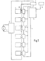
- the supply of the electric motor 3 is provided by a plurality 2 batteries connected in series via a 3 'drive.
- the use of a plurality of batteries in series for vehicle propulsion is made necessary because of the low value, around ten volts, the voltage across a single battery.
- the electric motors fitted to a motor vehicle require a supply voltage of the order of the hundred Volt.
- losses by Joule effect in the conductors decrease with increasing the source voltage feed.
- the batteries have preferably identical characteristics.
- each battery 2 At the terminals of each battery 2 are connected respectively the inputs E + and E - of a and of a single module 1.
- a first connecting conductor 4 connects in series the central unit 6 and the modules 1 between them.
- a second connecting conductor 5 connects at parallel alert means 7 and modules 1 between them.
- Each module 1 is self-powered from battery 2 it controls, but only consumes one negligible current compared to self-discharge of said battery.
- the alert means 7 are connected on the one hand to the positive terminal B + of all the batteries 2 connected in series and on the other hand to the output S of each module 1 via the second connection conductor 5.
- Selection means 8 are connected to the unit central 6.
- the means of selection which can consist of a numerical keyboard arranged on the dashboard and connected to the central unit.
- These selection means 8 allow the driver or to a computer, preprogrammed, choose the battery discharge threshold from from which alert means 7 will be activated in order to take appropriate action.
- These measures can be diverse depending on the discharge threshold of the selected battery, thus a threshold of 100% battery discharge requires immediate recharging of the batteries if you don't want not deteriorate it while a threshold of 80% selected discharge will require only a reduction in vehicle speed for save the residual battery charge.
- the central unit 6 includes combination means 6a which transform the value of the displayed discharge threshold using the selection means in a threshold of voltage.
- the electromotive force of a battery is indeed to some extent representative of the residual electric charge contained in this one.
- the combination means receive in input of signals I, T and s representative to each instant respectively of the current delivered by all batteries, temperature ambient and the discharge threshold value selected. These signals are delivered by sensors known elsewhere and not shown.
- the voltage threshold corresponding to the discharge chosen using the selection means 7 is determined by the combining means 6a.
- the residual charge Q res contained in a battery at a given instant and therefore the discharge threshold of the latter relative to a nominal state of charge can in fact be estimated according to a known method which consists in integrating with respect to time the current I delivered by the latter, between an instant when the charge of the latter is known and the instant t at which it is desired to know the residual charge Q res .
- this method is only applicable under conditions, temperature in particular, constant during the measurement.
- Conversion means 6b installed in the unit control panel receive as input the signal delivered by the combination means and transform this last in a control signal generated under the as a width modulated periodic signal pulse: the control signal includes a amplitude level A 'and duration a * T followed by duration zero amplitude level (a-1) * T.
- the parameter a between 0 and 1, is determined by function of the discharge threshold selected using means of selection.
- each module 1 includes comparator means 1c connected with a goes to a reference voltage source 1b and on the other hand to a processing means 1a.
- the reference voltage source consists of a Zener diode Z1 connected in series with a resistance R1.
- a 1d switch slaved to the output of the medium comparator 1c is connected to the output S of module 1.
- the switch 1d consists of per a diode D2 connected in series with a transistor T2 MOSFET.
- each module 1 comprises a supply line L + connected to the input E + of the module and a supply line L- connected to the input E - .
- a resistor R1 is connected in series with a Zener diode Z1.
- a capacitor C1 is mounted between the line L- and the point in common between the resistance R1 and diode Z1.
- An R2 resistor is mounted between the common point between diode Z1 and resistor R1 and the input non-inverting of a comparator A.
- a resistance R3 is mounted between the non-inverting input and the comparator A output.
- comparator A The positive supply terminal of comparator A is connected to line L-.
- the negative terminal comparator supply is connected to the line L-.
- the means 1a treatment includes an optocoupler associated with an RC circuit.
- the optocoupler is composed known from a light-emitting diode D1 arranged vis-à-vis with a T1 optotransistor.
- the optocouplers of each module 1 are connected in series through the first conductor of connection 4.
- a low-pass filter type RC composed elements R5, R4, D3 and C2 whose arrangement between them was previously described, went up between the transmitter of the optotransistor T1 and the input inverting comparator A.
- the cathode of the diode is connected to the optotransistor transmitter.
- the optotransistor collector is connected to the line L +.
- Switch 1d is slaved to the output of the comparator A and consists of a diode D2 connected by its cathode to the drain of transistor T2 and by its anode at the output S of the module.
- the source of transistor T2 is connected to the line supply L-.
- the output of comparator A is connected to the gate of a T2 MOSFET transistor.
- the value of the tension present on the wire emission 5 is equal to the voltage value measured between the terminals of the entire plurality of batteries.
- the batteries are discharged gradually, which induces a drop in blood pressure across these.
- the voltage V c across the capacitor C2 is equal to the average value of the voltage V RC applied to the input of the RC circuit. This value is equal to a * V batt taking into account the form of the control signal I uc , generated by the central unit.
- the established regime is achieved after a few successive charge and discharge cycles of the capacitor through the charge resistance R5 and the discharge resistance R4 respectively.
- the load resistor is short-circuited during the discharge phase of the capacitor through the resistor R4.
- the comparator means A compares the reference voltage Vref applied to its non-inverting input and the voltage a * V batt , which therefore amounts to comparing the voltage V batt with the ratio V ref / a.
- Vref reference voltage
- V batt voltage a * V batt
- the transmission wire 5 is at high impedance and the diode 7 "a of the optocoupler of the alert means 7 is blocked, the indicator light 7b
- the switching of the output of the comparator means causes the MOSFET T2 transistor to go from the blocked state to the on state.
- present on the input E - of the module is transferred to the transmission wire 5.
- a current therefore flows on the transmission wire, the diode 7 "a turns on which causes the indicator 7b to light up.
- the proposed device therefore makes it possible to detect simply a discharge threshold of at least one battery of a set of batteries mounted in series. This discharge threshold is selected by the driver.
- the device can be used for check all types of batteries.
- each module is self-powered on the battery it controls without penalizing however the charge of it because consuming only one current negligible compared to self-discharge of the latter.
Landscapes
- Physics & Mathematics (AREA)
- General Physics & Mathematics (AREA)
- Secondary Cells (AREA)
- Charge And Discharge Circuits For Batteries Or The Like (AREA)
- Tests Of Electric Status Of Batteries (AREA)
Description
- Une source de tension de référence,
- Un moyen de traitement relié d'une part respectivement aux bornes de la batterie et d'autre part à un premier conducteur de liaison d'une unité centrale à l'ensemble des modules montés en série,
- Un moyen comparateur relié d'une part au générateur et d'autre part au moyen de traitement,
- Un interrupteur asservi à la sortie du moyen comparateur,
- la figure 1 est une représentation schématique d'une installation mettant en oeuvre le dispositif suivant la présente invention,
- la figure 2 est une représentation schématique du synoptique fonctionnel correspondant à un module du dispositif conforme à l'invention,
- la figure 3 est un schéma fonctionnel de l'unité centrale du dispositif suivant l'invention,
- la figure 4 est un exemple de réalisation des moyens d'alerte représenté à la figure 1,
- la figure 5 est un exemple de réalisation du circuit électronique constitutif d'un module,
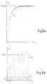
- les figures 6a et 6b représentent l'évolution du signal Vc délivré en sortie du moyen de traitement en fonction du temps pour différentes valeurs de composants électroniques dudit moyen de traitement.
Claims (4)
- Dispositif de contrôle de la décharge d'une pluralité de batteries montées comprenant une pluralité de modules (1) individuels identiques respectivement montés en parallèle aux bornes de chacune des batteries (2) et en ce que chaque module (1) possède :et en ce que ledit module (1) commande des moyens d'alerte (7) d'un seuil de décharge de la batterie aux bornes de laquelle il est montée.Une source de tension de référence (1b),Un moyen de traitement (la) relié d'une part respectivement aux bornes (E+,E-) de la batterie (2) et d'autre part à un premier conducteur de liaison (4) d'une unité centrale (6) à l'ensemble des modules (1) montés en série,Un moyen comparateur (1c) relié d'une part à la source (1b) et d'autre part au moyen de traitement (1a),Un interrupteur (1d) asservi à la sortie du moyen comparateur (1c),
- Dispositif selon la revendication 1 caractérisé en ce que le seuil de décharge est réglé par un signal de commande généré par l'unité centrale (6) et transmis simultanément à l'ensemble des modules (1) par le premier conducteur de liaison (4).
- Dispositif selon la revendication 1 caractérisé en ce que le moyen de traitement (1a) est constitué par un photocoupleur associé à un circuit RC.
- Dispositif selon la revendication 1 caractérisé en ce que l'interrupteur (1d) est constitué par un transistor MOSFET (T2) associé à une diode (D2).
Applications Claiming Priority (2)
| Application Number | Priority Date | Filing Date | Title |
|---|---|---|---|
| FR9310708A FR2709832B1 (fr) | 1993-09-09 | 1993-09-09 | Dispositif de contrôle de la décharge d'une pluralité de batteries montées en série. |
| FR9310708 | 1993-09-09 |
Publications (2)
| Publication Number | Publication Date |
|---|---|
| EP0643310A1 EP0643310A1 (fr) | 1995-03-15 |
| EP0643310B1 true EP0643310B1 (fr) | 2001-11-07 |
Family
ID=9450678
Family Applications (1)
| Application Number | Title | Priority Date | Filing Date |
|---|---|---|---|
| EP94402020A Expired - Lifetime EP0643310B1 (fr) | 1993-09-09 | 1994-09-09 | Dispositif de contrôle de la décharge d'une pluralité de batteries montées en série |
Country Status (4)
| Country | Link |
|---|---|
| EP (1) | EP0643310B1 (fr) |
| DE (1) | DE69428959T2 (fr) |
| ES (1) | ES2166772T3 (fr) |
| FR (1) | FR2709832B1 (fr) |
Families Citing this family (3)
| Publication number | Priority date | Publication date | Assignee | Title |
|---|---|---|---|---|
| EP1662268A1 (fr) * | 2004-11-30 | 2006-05-31 | "VLAAMSE INSTELLING VOOR TECHNOLOGISCH ONDERZOEK", afgekort "V.I.T.O." | Systeme et procedé permettant de mesurer la tension d'un empilement de piles à combustible |
| EP2259079A1 (fr) * | 2009-05-27 | 2010-12-08 | Belenos Clean Power Holding AG | Système de mesure de tension des cellules d'une pile à combustible |
| CN114167288B (zh) * | 2021-12-01 | 2023-12-08 | 贵州电网有限责任公司 | 一种单体蓄电池组电压稳定采集系统 |
Family Cites Families (7)
| Publication number | Priority date | Publication date | Assignee | Title |
|---|---|---|---|---|
| FR2537785A1 (fr) * | 1982-12-13 | 1984-06-15 | Electricite De France | Dispositif de controle de la capacite d'une batterie d'elements d'accumulateur |
| CA1295011C (fr) * | 1986-12-23 | 1992-01-28 | Warren T. Whitmire | Systeme de surveillance et de controle pour batterie d'accumulateurs |
| DE3702591A1 (de) * | 1987-01-29 | 1988-08-11 | Sonnenschein Accumulatoren | Schaltung zur laufenden ueberpruefung der qualitaet einer mehrzelligen batterie |
| JPH0717014Y2 (ja) * | 1989-05-26 | 1995-04-19 | シャープ株式会社 | 電池の寿命検出装置 |
| DE3940928C1 (fr) * | 1989-12-12 | 1991-07-11 | Fraunhofer-Gesellschaft Zur Foerderung Der Angewandten Forschung Ev, 8000 Muenchen, De | |
| GB2261735A (en) * | 1991-11-20 | 1993-05-26 | Chloride Silent Power Ltd | Battery monitoring and management system |
| GB2261958A (en) * | 1991-11-21 | 1993-06-02 | Chloride Silent Power Ltd | Monitoring the voltage of a dc supply |
-
1993
- 1993-09-09 FR FR9310708A patent/FR2709832B1/fr not_active Expired - Fee Related
-
1994
- 1994-09-09 EP EP94402020A patent/EP0643310B1/fr not_active Expired - Lifetime
- 1994-09-09 ES ES94402020T patent/ES2166772T3/es not_active Expired - Lifetime
- 1994-09-09 DE DE69428959T patent/DE69428959T2/de not_active Expired - Fee Related
Also Published As
| Publication number | Publication date |
|---|---|
| EP0643310A1 (fr) | 1995-03-15 |
| DE69428959D1 (de) | 2001-12-13 |
| FR2709832B1 (fr) | 1995-11-17 |
| DE69428959T2 (de) | 2002-06-06 |
| FR2709832A1 (fr) | 1995-03-17 |
| ES2166772T3 (es) | 2002-05-01 |
Similar Documents
| Publication | Publication Date | Title |
|---|---|---|
| EP0261118B1 (fr) | Alimentation en energie electrique de circuits sur la roue pour un dispositif de surveillance des pneumatiques | |
| EP2890990B1 (fr) | Dispositf de détéction et de mesure d'un défaut d'isolement | |
| FR2713019A1 (fr) | Procédé et dispositif de surveillance et d'équilibrage dynamique d'un pack de batteries d'accumulateurs. | |
| FR2760163A1 (fr) | Appareil de telecommunication muni d'un dispositif de reconnaissance de peripheriques | |
| EP2416468A2 (fr) | Procédé d'équilibrage pour batterie électrique et système de gestion pour batterie mettant en ouvre un tel procédé | |
| EP3036549A1 (fr) | Procede de detection d'une deconnexion de batterie d'alimentation d'un vehicule automobile | |
| FR2845050A1 (fr) | Lampe de vehicule avec circuit de detection de defaillance de diode photoemissive | |
| EP2464198B1 (fr) | Dispositif et procédé d'alimentation pour système d'éclairage à diodes électroluminescentes et ensemble d'éclairage comportant un tel dispositif | |
| WO2011027056A1 (fr) | Alternateur a redressement synchrone pour vehicule automobile, equipe de moyens electroniques de gestion de defauts | |
| EP0643310B1 (fr) | Dispositif de contrôle de la décharge d'une pluralité de batteries montées en série | |
| EP0809342B1 (fr) | Agencement pour le contrôle de la charge d'un ensemble modulaire de cellules électrochimiques raccordées en série et module correspondant de mesure pour cellule | |
| EP1139361B1 (fr) | Circuit électrique pour la transmission d'une information d'état, notamment d'un organe de matériel ferroviaire roulant, et système électrique incorporant un tel circuit | |
| CH660808A5 (fr) | Detecteur de feu de type analogique. | |
| FR2562733A1 (fr) | Regulateur de tension pour alternateur destine a la charge d'une batterie, notamment sur un vehicule automobile | |
| EP0092284A2 (fr) | Procédé et système de transmission de données sur une ligne d'alimentation | |
| FR2572860A1 (fr) | Regulateur electronique d'alternateur destine a la charge d'une batterie, notamment pour vehicule automobile | |
| FR2719123A1 (fr) | Dispositif de détection de la variation non transitoire d'une tension d'alimentation. | |
| EP0549464A1 (fr) | Procédé de mesure de l'état de charge d'un générateur électro-chimique et dispositif mettant en oeuvre ce procédé | |
| FR2674382A1 (fr) | Dispositif de regulation de tension de sortie pour alternateur. | |
| EP2916426B1 (fr) | Dispositif d'éclairage tel qu'un bloc autonome d'éclairage de sécurité et procédé d'alimentation électrique d'un microcontrôleur dans un tel dispositif d'éclairage | |
| FR2870996A1 (fr) | Protection de circuit electrique en mode veille pour vehicule | |
| FR2712747A1 (fr) | Dispositif d'alimentation d'une charge résistive à partir d'une batterie de stockage d'énergie d'un véhicule. | |
| EP3092817B1 (fr) | Procédé de communication avec un circuit de contrôle d'une batterie d'accumulateurs | |
| FR3075510A1 (fr) | Outil electromecanique portatif comportant un moteur alimente par un ensemble de condensateurs charges par au moins une batterie | |
| FR2468940A1 (fr) | Regulateur de tension pour alternateur destine a la charge d'une batterie |
Legal Events
| Date | Code | Title | Description |
|---|---|---|---|
| PUAI | Public reference made under article 153(3) epc to a published international application that has entered the european phase |
Free format text: ORIGINAL CODE: 0009012 |
|
| AK | Designated contracting states |
Kind code of ref document: A1 Designated state(s): DE ES GB IT |
|
| 17P | Request for examination filed |
Effective date: 19950829 |
|
| 17Q | First examination report despatched |
Effective date: 19990916 |
|
| GRAG | Despatch of communication of intention to grant |
Free format text: ORIGINAL CODE: EPIDOS AGRA |
|
| GRAG | Despatch of communication of intention to grant |
Free format text: ORIGINAL CODE: EPIDOS AGRA |
|
| GRAH | Despatch of communication of intention to grant a patent |
Free format text: ORIGINAL CODE: EPIDOS IGRA |
|
| GRAH | Despatch of communication of intention to grant a patent |
Free format text: ORIGINAL CODE: EPIDOS IGRA |
|
| GRAA | (expected) grant |
Free format text: ORIGINAL CODE: 0009210 |
|
| AK | Designated contracting states |
Kind code of ref document: B1 Designated state(s): DE ES GB IT |
|
| REF | Corresponds to: |
Ref document number: 69428959 Country of ref document: DE Date of ref document: 20011213 |
|
| REG | Reference to a national code |
Ref country code: GB Ref legal event code: IF02 |
|
| GBT | Gb: translation of ep patent filed (gb section 77(6)(a)/1977) |
Effective date: 20020110 |
|
| RAP2 | Party data changed (patent owner data changed or rights of a patent transferred) |
Owner name: RENAULT |
|
| REG | Reference to a national code |
Ref country code: ES Ref legal event code: FG2A Ref document number: 2166772 Country of ref document: ES Kind code of ref document: T3 |
|
| RAP2 | Party data changed (patent owner data changed or rights of a patent transferred) |
Owner name: RENAULT S.A.S. |
|
| PLBE | No opposition filed within time limit |
Free format text: ORIGINAL CODE: 0009261 |
|
| STAA | Information on the status of an ep patent application or granted ep patent |
Free format text: STATUS: NO OPPOSITION FILED WITHIN TIME LIMIT |
|
| 26N | No opposition filed | ||
| PGFP | Annual fee paid to national office [announced via postgrant information from national office to epo] |
Ref country code: GB Payment date: 20050830 Year of fee payment: 12 |
|
| PGFP | Annual fee paid to national office [announced via postgrant information from national office to epo] |
Ref country code: DE Payment date: 20050912 Year of fee payment: 12 |
|
| PGFP | Annual fee paid to national office [announced via postgrant information from national office to epo] |
Ref country code: ES Payment date: 20050920 Year of fee payment: 12 |
|
| PGFP | Annual fee paid to national office [announced via postgrant information from national office to epo] |
Ref country code: IT Payment date: 20060930 Year of fee payment: 13 |
|
| PG25 | Lapsed in a contracting state [announced via postgrant information from national office to epo] |
Ref country code: DE Free format text: LAPSE BECAUSE OF NON-PAYMENT OF DUE FEES Effective date: 20070403 |
|
| GBPC | Gb: european patent ceased through non-payment of renewal fee |
Effective date: 20060909 |
|
| PG25 | Lapsed in a contracting state [announced via postgrant information from national office to epo] |
Ref country code: GB Free format text: LAPSE BECAUSE OF NON-PAYMENT OF DUE FEES Effective date: 20060909 |
|
| REG | Reference to a national code |
Ref country code: ES Ref legal event code: FD2A Effective date: 20060911 |
|
| PG25 | Lapsed in a contracting state [announced via postgrant information from national office to epo] |
Ref country code: ES Free format text: LAPSE BECAUSE OF NON-PAYMENT OF DUE FEES Effective date: 20060911 |
|
| PG25 | Lapsed in a contracting state [announced via postgrant information from national office to epo] |
Ref country code: IT Free format text: LAPSE BECAUSE OF NON-PAYMENT OF DUE FEES Effective date: 20070909 |