EP0643362A2 - Appareil de lecture d'informations - Google Patents
Appareil de lecture d'informations Download PDFInfo
- Publication number
- EP0643362A2 EP0643362A2 EP94110638A EP94110638A EP0643362A2 EP 0643362 A2 EP0643362 A2 EP 0643362A2 EP 94110638 A EP94110638 A EP 94110638A EP 94110638 A EP94110638 A EP 94110638A EP 0643362 A2 EP0643362 A2 EP 0643362A2
- Authority
- EP
- European Patent Office
- Prior art keywords
- plane
- mirror
- information
- reading
- angle
- Prior art date
- Legal status (The legal status is an assumption and is not a legal conclusion. Google has not performed a legal analysis and makes no representation as to the accuracy of the status listed.)
- Granted
Links
Images


Classifications
-
- G—PHYSICS
- G06—COMPUTING OR CALCULATING; COUNTING
- G06K—GRAPHICAL DATA READING; PRESENTATION OF DATA; RECORD CARRIERS; HANDLING RECORD CARRIERS
- G06K7/00—Methods or arrangements for sensing record carriers, e.g. for reading patterns
- G06K7/10—Methods or arrangements for sensing record carriers, e.g. for reading patterns by electromagnetic radiation, e.g. optical sensing; by corpuscular radiation
- G06K7/10544—Methods or arrangements for sensing record carriers, e.g. for reading patterns by electromagnetic radiation, e.g. optical sensing; by corpuscular radiation by scanning of the records by radiation in the optical part of the electromagnetic spectrum
- G06K7/10554—Moving beam scanning
- G06K7/10594—Beam path
- G06K7/10683—Arrangement of fixed elements
- G06K7/10693—Arrangement of fixed elements for omnidirectional scanning
Definitions
- the invention relates to a device for reading information, in particular bar codes, with a light source which sends a bundled light beam to a deflection device, as a result of which the light beam - lying in a basic plane - travels back and forth within an angular range, with reflected light for a photoelectric converter Capture of information is fed.
- So-called scanners are used for this.
- These devices for reading information namely from the bar codes mentioned, each have a light source, which is preferably designed as a laser, which sends a bundled light beam to a deflection device, preferably a rotating mirror, whereby the light beam is fanned out lying in one plane becomes. If the bar code to be read is located in a reading plane which is penetrated by the basic plane, then this is detected by the light beam. Reflected light is fed to a photoelectric converter of the scanner, which receives the information recorded and evaluated.
- the scanning beam In order to be able to correctly detect the information content of the bar code, it is necessary for the scanning beam to sweep the entire bar code along its line of incidence during a beam passage. If only a partial number of the code gaps and code lines is detected, the information cannot be read completely. It is therefore important that the line of incidence of the scanning beam extends across the entire code, across the lines of the bar code. For the reading process, it is therefore necessary for the bar code to pass the line of incidence in a correspondingly aligned position, for example when goods provided with bar codes are guided past the scanner.
- an omni-directional reading that is to say a reading in which the bar code passes the scanner in a position-independent position
- two scanner devices each of which generates an impact line, the two impact lines crossing one another.
- An oversquared bar code is defined by the fact that its height (bar length) is greater than the width of the entire bar-and-gap arrangement, that is to say that the corresponding scanning beam will be able to detect all bars and gaps in one pass.
- the use of two scanner devices is relatively complex and expensive.
- the invention is therefore based on the object of providing a device for reading information which allows omni-directional reading and is nevertheless constructed in a very simple manner.
- an angular mirror is arranged in the area of the base plane, which has a first mirror plane and a second mirror plane, the first mirror plane and the second mirror plane for deflecting the light beam in an oblique-angled position passing through the base plane and further under one Angles run to one another such that a first scanning beam originating from the first mirror plane and a second scanning beam originating from the second mirror plane impinges on a reading plane in which the information is located, the line of incidence of the first one being used for omni-directional reading of the information Scanning beam extends transversely to the line of incidence of the second scanning beam and the two impinging beams preferably cross.
- the angle mirror which generates a scanning cross in the reading plane from the light beam originating from the light source, so that bar codes can be read in any position.
- the prerequisite here is that one beam passage is sufficient to detect all bars and gaps in the bar code.
- the barcode must therefore be oversquared.
- the two lines of contact run at right angles to one another.
- the two mirror planes adjoin one another to form a miter. This means a bevel at the collision of the two mirror levels.
- the deflection device is preferably designed as a rotating play polygon wheel.
- the light source can be designed as a laser.
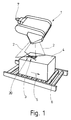
- FIG. 1 shows a device 1 for reading information, which scans a bar code 3 with optical scanning beams 2, which is located on a conveyed item 4 which moves in the direction of arrow 5 along a roller conveyor 6.
- the device 1 is held stationary by means of a frame, not shown.
- the read information that is to say the data of the bar code 3, is fed to a computer or a further processing device, for example by means of an electrical connection 7.
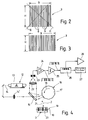
- FIG. 2 shows an example of a bar code 3 which has a multiplicity of thin and thick bars 8 and narrow and wide gaps 9.
- the length of the bars H is slightly larger than the width B of the entire bar code. It is therefore a so-called oversquared bar code 3, that is to say, when scanning by means of two, 90 ° including striking lines 10 and 11 of two scanning beams 2 of the device 1, at least one striking line (here the striking line 11) always penetrates the information content of all bars 8 and gaps 9, so that an omni-directional reading can take place. This means a possible determination of information in any position of the bar code.
- a light source 12 which is preferably designed as a laser 13, emits a light beam 14, which passes through a converging lens 14 ′, possibly deflected several times, and penetrates a semitransparent mirror 15 and then falls on a deflection device 16.
- the deflection device 16 is designed as a polygon wheel 17 provided with mirrors, which rotates at high speed (case 18). As a result, the light beam forming a scanning beam 2 is fed to a reading plane 19 in which the information 20, which is designed as a bar code 3, is located.
- the overall information of the bar code 3 is detected by the fact that, due to the rotation of the polygon wheel 17, the scanning beam swings back and forth within an angular range, so that its line of incidence 10 runs transversely, preferably perpendicularly, to the longitudinal bar extensions of the code.
- Reflected light 21 is thrown back from the bar code 3 to the polygon wheel 17 and from there reaches the semitransparent mirror 15, which supplies the reflected light 21 to a converging lens 22, which guides it to a photoelectric converter 23.
- the data corresponding to the information are an amplifier 24 and a Digitizing stage 25 and a decoder 26, which displays the information on a display 27 or feeds an interface 28.
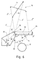
- FIG. 5 shows a housing 30 in which the polygon wheel 17, the semitransparent mirror 15, the laser 13, the converging lens 22, the photoelectric converter 23 and electronic devices 31 are located. Further assemblies, which are also necessary for the function of the device 1, have been neglected in FIG. 5 for reasons of simplification. The peculiarity of the angle mirror 29 is discussed with the aid of the schematic illustration in FIG. 6.
- the light beam 14 coming from the rotating polygon wheel 17 — lying in a base plane 32 — is pivoted back and forth within an angular range ⁇ .
- the angle ⁇ is preferably 90 °. It strikes two mirror planes 33 and 34 of the angular mirror 29.
- the mirror plane 33 forms a first mirror plane;
- mirror plane 34 is a second mirror plane.
- the two mirror planes 33 and 34 penetrate the basic plane 32 in an oblique-angled position, forming an acute angle ⁇ , which is a step angle ⁇ 'corresponding to the triangular cross-sectional periphery of the angle mirror 29 repeated.
- the angle ⁇ or ⁇ ' is preferably 34 °.
- the two mirror planes 33 and 34 form a bevel 35 at their collision 36, that is to say they adjoin one another to form a miter 37.
- the angle mirror 29 reflects from the light beam 14 scanning beams 2 'and 2'', which produce two lines of incidence 10 and 11 in a reading plane 19, which extend transversely to one another and cross each other.
- the word "transverse” does not necessarily mean that it is a 90 ° angle between the two lines of incidence 10 and 11. However, it is preferably provided that the angle between the two lines of incidence 10 and 11 is rectangular.
- the mirror plane 33 generates scanning beams 2 '.
- the mirror plane 34 emits scanning beams 2 ′′.
- the scanning beams 2 'and 2'' only the "end" beams are shown.
- the scanning beams 2 'and 2'' result from the reflection of the light beam 14, which strikes both mirror planes 33 and 34 along lines of incidence 38' and 39 '.
- the line of incidence 10 is formed in the reading plane 19 between the scanning beams 2 'and the line of incidence 11 between the scanning beams 2''.
- the two mirror planes 33 and 34 form an angle ⁇ between them.
- the angle ⁇ is preferably 90 °. This is shown in FIG. 6.
- the angle ⁇ forms between the lower longitudinal edges 38 and 39 of the two mirror planes 33 and 34, provided that the longitudinal edges 38 and 39 are parallel to the lines of incidence 38 'and 39' of the light beam 14 on the mirror planes 33 and 34. Due to the geometrical relationships, however, the angle ⁇ is also formed in the base plane 32 between the two mirror planes 33 and 34. This is also shown in Figure 6 for clarification.
- An opened device 1 is shown again in FIG. 7 for further clarification.
- the angle mirror 29 is located in an additional housing 30 'which can be fastened to the housing 30.
- the device 1 which is designed as a single-beam scanner, can be converted into a cross-beam scanner, so that omni-directional reading is possible. The corresponding effort is therefore very low.
- the angle mirror it is also possible for the angle mirror to be arranged in the scanner housing.
- the electronic devices 31 of the exemplary embodiment in FIG. 7 enable an omni-directional reading of a bar code 3 even if it is designed as not oversquared. This is done in that when passing the bar code, the striking lines 10 and 11 scan the bar code 3 "in slices", that is to say the reading is carried out with each beam passage and the result is stored in an electronic memory. If the next beam passage takes place, the bar code has moved on due to the conveying material 4 moving past, so that other positions of the bar code along the Impact lines 10 and 11 are detected. This process takes place several times until the total information is formed by electronically assembling the various stored partial information and is found as a result of the reading.
Landscapes
- Physics & Mathematics (AREA)
- Engineering & Computer Science (AREA)
- Electromagnetism (AREA)
- Artificial Intelligence (AREA)
- Toxicology (AREA)
- General Health & Medical Sciences (AREA)
- Health & Medical Sciences (AREA)
- Computer Vision & Pattern Recognition (AREA)
- General Physics & Mathematics (AREA)
- Theoretical Computer Science (AREA)
- Mechanical Optical Scanning Systems (AREA)
- Discharge Of Articles From Conveyors (AREA)
- Facsimile Scanning Arrangements (AREA)
Priority Applications (1)
| Application Number | Priority Date | Filing Date | Title |
|---|---|---|---|
| DE9422422U DE9422422U1 (de) | 1993-09-15 | 1994-07-08 | Vorrichtung zum Lesen von Informationen |
Applications Claiming Priority (2)
| Application Number | Priority Date | Filing Date | Title |
|---|---|---|---|
| DE4331105A DE4331105A1 (de) | 1993-09-15 | 1993-09-15 | Vorrichtung zum Lesen von Informationen |
| DE4331105 | 1993-09-15 |
Publications (4)
| Publication Number | Publication Date |
|---|---|
| EP0643362A2 true EP0643362A2 (fr) | 1995-03-15 |
| EP0643362A3 EP0643362A3 (fr) | 1998-11-11 |
| EP0643362B1 EP0643362B1 (fr) | 2001-12-12 |
| EP0643362B2 EP0643362B2 (fr) | 2009-12-30 |
Family
ID=6497638
Family Applications (1)
| Application Number | Title | Priority Date | Filing Date |
|---|---|---|---|
| EP94110638A Expired - Lifetime EP0643362B2 (fr) | 1993-09-15 | 1994-07-08 | Appareil de lecture d'informations |
Country Status (2)
| Country | Link |
|---|---|
| EP (1) | EP0643362B2 (fr) |
| DE (2) | DE4331105A1 (fr) |
Cited By (1)
| Publication number | Priority date | Publication date | Assignee | Title |
|---|---|---|---|---|
| US7128267B2 (en) | 2003-07-11 | 2006-10-31 | Sick Ag | Device for optical scanning of objects, especially markings |
Families Citing this family (1)
| Publication number | Priority date | Publication date | Assignee | Title |
|---|---|---|---|---|
| DE19543656A1 (de) * | 1995-11-23 | 1997-05-28 | Kodak Ag | Verfahren und Vorrichtung zum Abtasten eines Barcodes |
Citations (3)
| Publication number | Priority date | Publication date | Assignee | Title |
|---|---|---|---|---|
| EP0359010A1 (fr) | 1988-08-26 | 1990-03-21 | Accu-Sort Systems, Inc. | Dispositif de balayage en X |
| EP0424096A1 (fr) | 1989-10-16 | 1991-04-24 | Fujitsu Limited | Lecteur de code à batônnets |
| EP0452274A2 (fr) | 1990-04-12 | 1991-10-16 | Dainippon Ink And Chemicals, Inc. | Dérivés de phénylcyclohexyldioxane ayant une liaison éther pour matériel électro-optique |
Family Cites Families (7)
| Publication number | Priority date | Publication date | Assignee | Title |
|---|---|---|---|---|
| DE2419935C3 (de) * | 1974-04-25 | 1980-05-08 | Erwin Sick Gmbh Optik-Elektronik, 7808 Waldkirch | Einrichtung zum Lesen von Codes |
| JPS60102609A (ja) * | 1983-11-10 | 1985-06-06 | Fujitsu Ltd | 光走査装置 |
| US4816661A (en) * | 1986-12-22 | 1989-03-28 | Symbol Technologies, Inc. | Scan pattern generators for bar code symbol readers |
| US5245170A (en) * | 1988-12-20 | 1993-09-14 | Fujitsu Limited | Optical scanner using planar reflection holograms |
| US5206491A (en) * | 1990-03-02 | 1993-04-27 | Fujitsu Limited | Plural beam, plural window multi-direction bar code reading device |
| US5214270A (en) † | 1991-11-22 | 1993-05-25 | Spectra-Physics | Modular handheld or fixed scanner |
| EP0553504A1 (fr) * | 1992-01-28 | 1993-08-04 | Opticon Sensors Europe B.V. | Système de balayage optique utilisant un chopper optique |
-
1993
- 1993-09-15 DE DE4331105A patent/DE4331105A1/de not_active Withdrawn
-
1994
- 1994-07-08 DE DE59410001T patent/DE59410001D1/de not_active Expired - Lifetime
- 1994-07-08 EP EP94110638A patent/EP0643362B2/fr not_active Expired - Lifetime
Patent Citations (3)
| Publication number | Priority date | Publication date | Assignee | Title |
|---|---|---|---|---|
| EP0359010A1 (fr) | 1988-08-26 | 1990-03-21 | Accu-Sort Systems, Inc. | Dispositif de balayage en X |
| EP0424096A1 (fr) | 1989-10-16 | 1991-04-24 | Fujitsu Limited | Lecteur de code à batônnets |
| EP0452274A2 (fr) | 1990-04-12 | 1991-10-16 | Dainippon Ink And Chemicals, Inc. | Dérivés de phénylcyclohexyldioxane ayant une liaison éther pour matériel électro-optique |
Cited By (1)
| Publication number | Priority date | Publication date | Assignee | Title |
|---|---|---|---|---|
| US7128267B2 (en) | 2003-07-11 | 2006-10-31 | Sick Ag | Device for optical scanning of objects, especially markings |
Also Published As
| Publication number | Publication date |
|---|---|
| EP0643362B2 (fr) | 2009-12-30 |
| DE59410001D1 (de) | 2002-01-24 |
| EP0643362A3 (fr) | 1998-11-11 |
| DE4331105A1 (de) | 1995-03-16 |
| EP0643362B1 (fr) | 2001-12-12 |
Similar Documents
| Publication | Publication Date | Title |
|---|---|---|
| DE3853494T2 (de) | Anordnung zur Erzeugung eines optischen Abtastrasters für Laserabtaster. | |
| DE69126338T2 (de) | Vorrichtung zum Lesen von Strichkodierungen | |
| DE68908795T2 (de) | Strahlenoptisches Abtastsystem zum Lesen von Strich-Codes. | |
| DE2508153C3 (de) | Optisches Lesegerät | |
| DE2332595C2 (de) | Vorrichtung zum Lesen optischer Codemuster | |
| DE2914509C2 (fr) | ||
| DE3854885T2 (de) | Kombinieren von gelesenen Strichcode-Daten | |
| DE2526726A1 (de) | Richtungsunabhaengige abtastvorrichtung | |
| DE2131467C3 (de) | Lichtablenkvorriehtung zur Parallelverschiebung eines Lichtstrahls | |
| DE2528058A1 (de) | Richtungsunabhaengige abtastvorrichtung | |
| DE2449958B2 (de) | Code-lesevorrichtung | |
| CH622896A5 (fr) | ||
| DE69119564T2 (de) | Optisches Abtastgerät | |
| DE3611536A1 (de) | Vorrichtung zur automatischen ueberpruefung von transparenten objekten, insbesondere von glasflaschen | |
| EP2728305A1 (fr) | Procédé, dispositif et modèle lumineux pour mesurer la hauteur ou le trajet en hauteur d'un objet | |
| EP1339007B1 (fr) | Lecteur optoélectronique des codes | |
| DE3805455C2 (fr) | ||
| DE69418769T2 (de) | Optischer Abtaster für Strichcode | |
| DE2338295A1 (de) | Vorrichtung zum auffinden von fehlern in flaechen | |
| DE19711873C2 (de) | Verfahren und Vorrichtung zum Lesen eines Strichcodes | |
| DE3939838A1 (de) | Vorrichtung zur korrektur eines abtaststrahles auf der basis des kippens von oberflaechensegmenten eines vieleckigen spiegels, die in abtastmuster-zeichenvorrichtungen verwendet werden | |
| DE69631618T2 (de) | Zweiteilungsabtastsystem zur Detektion von überlappenden Gegenständen | |
| DE69716393T3 (de) | Vorrichtung zum Abtasten eines sich auf einem bewegenden Artikel befindlichen optischen Kodes und Verfahren zum Abtasten eines solchen optischen Kodes mittels dieser Abtastvorrichtung | |
| DE2756253A1 (de) | Lichtabtastvorrichtung | |
| EP0643362A2 (fr) | Appareil de lecture d'informations |
Legal Events
| Date | Code | Title | Description |
|---|---|---|---|
| PUAI | Public reference made under article 153(3) epc to a published international application that has entered the european phase |
Free format text: ORIGINAL CODE: 0009012 |
|
| AK | Designated contracting states |
Kind code of ref document: A2 Designated state(s): DE FR GB IT |
|
| PUAL | Search report despatched |
Free format text: ORIGINAL CODE: 0009013 |
|
| AK | Designated contracting states |
Kind code of ref document: A3 Designated state(s): DE FR GB IT |
|
| 17P | Request for examination filed |
Effective date: 19990511 |
|
| 17Q | First examination report despatched |
Effective date: 20000605 |
|
| GRAG | Despatch of communication of intention to grant |
Free format text: ORIGINAL CODE: EPIDOS AGRA |
|
| GRAG | Despatch of communication of intention to grant |
Free format text: ORIGINAL CODE: EPIDOS AGRA |
|
| GRAH | Despatch of communication of intention to grant a patent |
Free format text: ORIGINAL CODE: EPIDOS IGRA |
|
| GRAH | Despatch of communication of intention to grant a patent |
Free format text: ORIGINAL CODE: EPIDOS IGRA |
|
| GRAA | (expected) grant |
Free format text: ORIGINAL CODE: 0009210 |
|
| AK | Designated contracting states |
Kind code of ref document: B1 Designated state(s): DE FR GB IT |
|
| REG | Reference to a national code |
Ref country code: GB Ref legal event code: IF02 |
|
| GBT | Gb: translation of ep patent filed (gb section 77(6)(a)/1977) |
Effective date: 20011212 |
|
| REF | Corresponds to: |
Ref document number: 59410001 Country of ref document: DE Date of ref document: 20020124 |
|
| ET | Fr: translation filed | ||
| PLBQ | Unpublished change to opponent data |
Free format text: ORIGINAL CODE: EPIDOS OPPO |
|
| PLBI | Opposition filed |
Free format text: ORIGINAL CODE: 0009260 |
|
| PLBF | Reply of patent proprietor to notice(s) of opposition |
Free format text: ORIGINAL CODE: EPIDOS OBSO |
|
| PLBQ | Unpublished change to opponent data |
Free format text: ORIGINAL CODE: EPIDOS OPPO |
|
| PLAB | Opposition data, opponent's data or that of the opponent's representative modified |
Free format text: ORIGINAL CODE: 0009299OPPO |
|
| 26 | Opposition filed |
Opponent name: SICK AG Effective date: 20020909 |
|
| R26 | Opposition filed (corrected) |
Opponent name: SICK AG Effective date: 20020909 |
|
| PLBF | Reply of patent proprietor to notice(s) of opposition |
Free format text: ORIGINAL CODE: EPIDOS OBSO |
|
| APBP | Date of receipt of notice of appeal recorded |
Free format text: ORIGINAL CODE: EPIDOSNNOA2O |
|
| APBQ | Date of receipt of statement of grounds of appeal recorded |
Free format text: ORIGINAL CODE: EPIDOSNNOA3O |
|
| APAA | Appeal reference recorded |
Free format text: ORIGINAL CODE: EPIDOS REFN |
|
| RAP2 | Party data changed (patent owner data changed or rights of a patent transferred) |
Owner name: DATALOGIC S.P.A. |
|
| REG | Reference to a national code |
Ref country code: GB Ref legal event code: 732E |
|
| APAH | Appeal reference modified |
Free format text: ORIGINAL CODE: EPIDOSCREFNO |
|
| APAH | Appeal reference modified |
Free format text: ORIGINAL CODE: EPIDOSCREFNO |
|
| APAH | Appeal reference modified |
Free format text: ORIGINAL CODE: EPIDOSCREFNO |
|
| APBU | Appeal procedure closed |
Free format text: ORIGINAL CODE: EPIDOSNNOA9O |
|
| PLAY | Examination report in opposition despatched + time limit |
Free format text: ORIGINAL CODE: EPIDOSNORE2 |
|
| PLBC | Reply to examination report in opposition received |
Free format text: ORIGINAL CODE: EPIDOSNORE3 |
|
| RAP2 | Party data changed (patent owner data changed or rights of a patent transferred) |
Owner name: DATALOGIC AUTOMATION S.R.L. |
|
| APBP | Date of receipt of notice of appeal recorded |
Free format text: ORIGINAL CODE: EPIDOSNNOA2O |
|
| APBQ | Date of receipt of statement of grounds of appeal recorded |
Free format text: ORIGINAL CODE: EPIDOSNNOA3O |
|
| APAH | Appeal reference modified |
Free format text: ORIGINAL CODE: EPIDOSCREFNO |
|
| APBU | Appeal procedure closed |
Free format text: ORIGINAL CODE: EPIDOSNNOA9O |
|
| PLAB | Opposition data, opponent's data or that of the opponent's representative modified |
Free format text: ORIGINAL CODE: 0009299OPPO |
|
| PUAH | Patent maintained in amended form |
Free format text: ORIGINAL CODE: 0009272 |
|
| STAA | Information on the status of an ep patent application or granted ep patent |
Free format text: STATUS: PATENT MAINTAINED AS AMENDED |
|
| 27A | Patent maintained in amended form |
Effective date: 20091230 |
|
| AK | Designated contracting states |
Kind code of ref document: B2 Designated state(s): DE FR GB IT |
|
| REG | Reference to a national code |
Ref country code: GB Ref legal event code: 732E Free format text: REGISTERED BETWEEN 20091210 AND 20091216 |
|
| PGFP | Annual fee paid to national office [announced via postgrant information from national office to epo] |
Ref country code: IT Payment date: 20110625 Year of fee payment: 18 |
|
| PGFP | Annual fee paid to national office [announced via postgrant information from national office to epo] |
Ref country code: DE Payment date: 20110708 Year of fee payment: 18 Ref country code: FR Payment date: 20110810 Year of fee payment: 18 Ref country code: GB Payment date: 20110701 Year of fee payment: 18 |
|
| GBPC | Gb: european patent ceased through non-payment of renewal fee |
Effective date: 20120708 |
|
| REG | Reference to a national code |
Ref country code: FR Ref legal event code: ST Effective date: 20130329 |
|
| PG25 | Lapsed in a contracting state [announced via postgrant information from national office to epo] |
Ref country code: DE Free format text: LAPSE BECAUSE OF NON-PAYMENT OF DUE FEES Effective date: 20130201 Ref country code: FR Free format text: LAPSE BECAUSE OF NON-PAYMENT OF DUE FEES Effective date: 20120731 Ref country code: GB Free format text: LAPSE BECAUSE OF NON-PAYMENT OF DUE FEES Effective date: 20120708 |
|
| REG | Reference to a national code |
Ref country code: DE Ref legal event code: R119 Ref document number: 59410001 Country of ref document: DE Effective date: 20130201 |
|
| PG25 | Lapsed in a contracting state [announced via postgrant information from national office to epo] |
Ref country code: IT Free format text: LAPSE BECAUSE OF NON-PAYMENT OF DUE FEES Effective date: 20120708 |