EP0643442B1 - Dispositif de raccordement de conducteurs électriques pour poste de dérivation ou de transformation - Google Patents
Dispositif de raccordement de conducteurs électriques pour poste de dérivation ou de transformation Download PDFInfo
- Publication number
- EP0643442B1 EP0643442B1 EP94420244A EP94420244A EP0643442B1 EP 0643442 B1 EP0643442 B1 EP 0643442B1 EP 94420244 A EP94420244 A EP 94420244A EP 94420244 A EP94420244 A EP 94420244A EP 0643442 B1 EP0643442 B1 EP 0643442B1
- Authority
- EP
- European Patent Office
- Prior art keywords
- jaws
- connection
- pair
- jaw
- screws
- Prior art date
- Legal status (The legal status is an assumption and is not a legal conclusion. Google has not performed a legal analysis and makes no representation as to the accuracy of the status listed.)
- Expired - Lifetime
Links
- 239000004020 conductor Substances 0.000 title claims abstract description 23
- 238000010079 rubber tapping Methods 0.000 title claims 4
- 229910052751 metal Inorganic materials 0.000 claims abstract description 8
- 239000002184 metal Substances 0.000 claims abstract description 8
- 238000005520 cutting process Methods 0.000 claims abstract description 4
- 239000000470 constituent Substances 0.000 claims 1
- RYGMFSIKBFXOCR-UHFFFAOYSA-N Copper Chemical compound [Cu] RYGMFSIKBFXOCR-UHFFFAOYSA-N 0.000 description 4
- 229910052782 aluminium Inorganic materials 0.000 description 3
- XAGFODPZIPBFFR-UHFFFAOYSA-N aluminium Chemical compound [Al] XAGFODPZIPBFFR-UHFFFAOYSA-N 0.000 description 3
- 229910052802 copper Inorganic materials 0.000 description 3
- 239000010949 copper Substances 0.000 description 3
- 238000009434 installation Methods 0.000 description 3
- 238000004519 manufacturing process Methods 0.000 description 3
- 239000000463 material Substances 0.000 description 3
- 229910000838 Al alloy Inorganic materials 0.000 description 1
- 229910000906 Bronze Inorganic materials 0.000 description 1
- 239000004411 aluminium Substances 0.000 description 1
- 239000010974 bronze Substances 0.000 description 1
- KUNSUQLRTQLHQQ-UHFFFAOYSA-N copper tin Chemical compound [Cu].[Sn] KUNSUQLRTQLHQQ-UHFFFAOYSA-N 0.000 description 1
- 238000009795 derivation Methods 0.000 description 1
- 238000005553 drilling Methods 0.000 description 1
- 238000003754 machining Methods 0.000 description 1
- 238000000034 method Methods 0.000 description 1
- 125000006850 spacer group Chemical group 0.000 description 1
- 230000009466 transformation Effects 0.000 description 1
Images


Classifications
-
- H—ELECTRICITY
- H01—ELECTRIC ELEMENTS
- H01R—ELECTRICALLY-CONDUCTIVE CONNECTIONS; STRUCTURAL ASSOCIATIONS OF A PLURALITY OF MUTUALLY-INSULATED ELECTRICAL CONNECTING ELEMENTS; COUPLING DEVICES; CURRENT COLLECTORS
- H01R4/00—Electrically-conductive connections between two or more conductive members in direct contact, i.e. touching one another; Means for effecting or maintaining such contact; Electrically-conductive connections having two or more spaced connecting locations for conductors and using contact members penetrating insulation
- H01R4/28—Clamped connections, spring connections
- H01R4/38—Clamped connections, spring connections utilising a clamping member acted on by screw or nut
- H01R4/46—Clamping area between two screws placed side by side
Definitions
- connection devices commonly referred to as post fittings.
- each fitting is made up of opposing jaws formed by a molded metal body, comprising one or two gutters integral with a fixing element, and molded metal flanges, these elements being tightened on the conductor by bolts passing through the body and the flanges.
- this manufacturing method requires make a mold for the body of each type of fitting, since the flanges can be used for different types of fittings.
- this method of manufacture is not interesting only for large series and is totally unsuitable for small series, since for any new type of fitting different from those existing by variations in shapes, dimensions or connection or fixing conditions, it you have to make a new mold, which leads to a heavy investment and lead times long manufacturing.
- connection device modular that can very quickly adapt to the needs of the demand by requiring no new mold investment.
- connection mode by bolts between body and flanges, connection requiring complete disassembly before installation and requiring numerous manipulations to replace the bolts, their nuts and washers after mounting the body and flanges on the conductors.
- Another object of the invention is to provide a connection device simplifying its installation while reducing the manipulations necessary for its assembly.
- each of the jaws is the result of cutting a desired length from an extruded metal profile, comprising at least one longitudinal and axial groove, constituting gutter, of shape and dimensions able to cooperate in clamping the conductor, while the connection between two jaws of a pair of opposite jaws is secured by screws whose ends threaded are screwed into threaded holes made in one of the jaws and whose bodies pass through bores in the other jaw, these threads and bores being distributed with a longitudinal pitch identical to their transverse pitch so that each pair of opposite jaws constitutes a modular element.
- each pair of jaws forms a modular element which can be assembled with another identical modular element, with its longitudinal axis arranged in the extension of that of the other element or perpendicular to this axis.
- Each modular element or several elements can be combined with various elements additional fixing and / or electrical connection to meet the connection needs, without the need to make investments expensive.
- At least two of the connecting screws between two jaws of the same pair of jaws are associated with a helical spring surrounding them and able to remove them.
- This structure spreads the jaws of each modular element when this the latter is at rest, and thus facilitates the connection maneuvers, since the operator only has to worry about engaging the conductors between the front jaws in this phase to tighten them.
- the modular elements are fixed on plates of fixing, rectilinear, bent or counter-bent, or on fixing legs.
- the device according to the invention is essentially composed of at least one pair A of jaws 2a-2b linked to each other by screws 3. Each jaw is cut to size desired length in a metal profile, aluminum alloy, bronze or copper, extruded or spun, that is to say formed by passing through a die.
- the profile comprises, emerging from one of its large faces, a longitudinal and axial groove 4, bordered by each side by two lateral grooves 5, parallel to it.
- the axial groove 4 has, in the embodiment shown, a semi-circular section, but it can also have a flat bottom and straight edges, when it is intended to clamp conductors of rectangular section.
- the two lateral grooves each have a flat bottom 5a bordered by two straight edges 5b.
- one of the jaws is subjected to a machining operation consisting in making transverse threads 6.
- the other jaw 2b is subjected to a drilling operation making bores transverse 7.
- the longitudinal pitch PL of the threads and bores is equal at their transverse step PT.
- At least two of the screws 3 ensuring the connection of the two jaws 2a and 2b, and more particularly two opposite screws, are each associated with a spring spacer 8 disposed around them and bearing on the bottom of the grooves 5. It will be noted that the ends of the springs 8 are positioned transversely by the edges 5b of the grooves side 5.
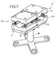
- a pair A of jaws forms a modular element which can be associated, depending on the needs of the installation, either with a connection area B to form a connection terminal, as shown in Figures 1 to 3, i.e. at a base C, as shown in figure 4. It can also be combined by a plate of connection 13 to at least one other pair of jaws to form a device for connection between two conductors, as shown in Figures 5 to 7. It is obvious that, depending on requirements, the jaws can be longer or shorter and can be linked to each other the other by four screws, six screws, or eight screws, arranged in modular steps PL and PT.
- the two jaws 2a-2b are associated with a plate of fixing 9 which is rectilinear and arranged, with its longitudinal axis, parallel to that of the gutter formed by the two axial grooves 4 of the two jaws.
- the plate 9 can also be arranged with its longitudinal axis perpendicular to that of the pair jaws, and there is no need to make any investment additional.
- the plate 9 may include, in its part not linked to the pair of jaws, a angled sector which, as required, can be arranged longitudinally or transversely to these jaws.
- Figure 3 shows that the fixing plate can also be bent at 9a and counter-bent at 9b, in its part disposed outside of its attachment zone with the jaws.
- the same pair of jaws A can form a foot connection by association with a base C having a threaded end 10 screwing into a threaded hole 12 formed transversely in one of the two jaws, and for example in that 2b.
- each modular element consisting of a pair of jaws A are connected to each other by a common connecting plate 13.
- these elements are arranged with their longitudinal axes at 90 °, but they can of course be arranged with their co-axial axes.
- these two elements can be combined with a third element to form a "T" connection, or several other elements to form a multiple connection.
- each modular element is made integral with the others by a fixing plate common to which it is itself fixed by its screws 3 ensuring the clamping of the jaws on the driver.
- Figure 6 shows a simplified version for end-to-end connection of two identical conductors or of diameter corresponding to the capacity of the jaws 2a and 2b, in which a jaw 2c of greater length than the jaws 2a of the two pairs A of jaws, and common to these two pairs of jaws and form element of connection between pairs of jaws.
- connection device of the type shown in FIG. 5, is connected by its fixing plate 13 to a base 14.
- This device therefore makes it possible, with a reduced investment, to reduce considerably the time required to make non-standard substation connections and thus to meet the needs, by series, small or large.
Landscapes
- Connections By Means Of Piercing Elements, Nuts, Or Screws (AREA)
- Insulated Conductors (AREA)
- Connections Effected By Soldering, Adhesion, Or Permanent Deformation (AREA)
- Multi-Conductor Connections (AREA)
- Housings And Mounting Of Transformers (AREA)
- Coupling Device And Connection With Printed Circuit (AREA)
Description
- de la forme de la section du conducteur, cylindrique ou rectangulaire, ce conducteur pouvant être un câble, un tube ou une barre,
- des dimensions de cette section,
- du nombre de conducteurs devant être raccordés, à savoir un, deux ou plus,
- des conditions de raccordement des conducteurs, par exemple bout à bout, en "T",
- des conditions de fixation sur un support nécessitant soit une plage, droite, coudée ou contrecoudée, soit un pied,
- et de la nature des matériaux des conducteurs pour les connexions monométalliques et bimétalliques, tels qu'aluminium et cuivre.
Claims (9)
- Dispositif de raccordement de conducteurs électriques pour poste de dérivation ou transformation, du type composé d'au moins une paire de mâchoires opposées, aptes à être serrées par une liaison filetée sur au moins un conducteur, caractérisé en ce que chacune des mâchoires (2a, 2b, 2c) résulte du découpage d'une longueur voulue d'un profilé métallique extrudé, comportant au moins une rainure longitudinale et axiale (4), constituant gouttière, de forme et dimensions aptes à coopérer au serrage du conducteur, tandis que la liaison entre deux mâchoires (2a-2b) d'une paire (A) de mâchoires opposées est assurée par des vis (3) dont les extrémités filetées se vissent dans des trous taraudés (6) réalisés dans l'une des mâchoires et dont les corps traversent des alésages (7) ménagés dans l'autre mâchoire, ces taraudages et alésages étant répartis avec un pas longitudinal (PL) identique à leur pas transversal (PT) de telle sorte que chaque paire de mâchoires opposées constitue un élément modulaire.
- Dispositif selon la revendication 1, caractérisé en ce que, au moins deux des vis de liaison (3) entre deux mâchoires (2a-2b ou 2c) d'une même paire de mâchoires sont associés à un moyen (8) apte à les écarter.
- Dispositif selon la revendication 2, caractérisé en ce que chaque mâchoire (2a, 2b, 2c) comporte, disposées de part et d'autre de la rainure axiale (4), et parallèlement à elle, deux rainures latérales (5) dont le fond (5a) forme face d'appui pour les extrémités correspondantes du ou des moyens écarteurs et dont les bords (5b) forment éléments de centrage transversal pour ces moyens écarteurs.
- Dispositif selon l'une quelconque des revendications 1 à 3, caractérisé en ce que, au moins l'une des paires (A) de mâchoires est liée, par ses vis de serrage (3) à une plaque de fixation (9).
- Dispositif selon la revendication 4, caractérisé en ce que la plaque de fixation (9) est rectiligne et assure la liaison d'au moins deux paires de mâchoires formant une connexion en "T".
- Dispositif selon la revendication 4, caractérisé en ce que la plaque de fixation (9) déborde de la mâchoire et forme plage de fixation.
- Dispositif selon l'une quelconque des revendications 1 à 5, caractérisé en ce que l'une des mâchoires (2a, 2b, 2c) d'au moins une paire de mâchoires est traversée par un taraudage central (12) pour l'extrémité filetée (10) d'un piètement de fixation (C).
- Dispositif selon l'une quelconque des revendications 1 à 3, caractérisé en ce que les mâchoires juxtaposées et indépendantes (2a) d'un ensemble de plusieurs paires de mâchoires sont liées à une mâchoire opposée commune (2c) s'étendant sur une longueur égale à l'encombrement en longueur des mâchoires indépendantes.
- Dispositif selon l'une quelconque des revendications 1 à 8, caractérisé en ce que en ce que chacun de ses éléments constitutifs, à savoir mâchoires (2a,2b, 2c), plaque de fixation (9) ou de liaison (13) et piètement (C) sont étamés.
Applications Claiming Priority (2)
| Application Number | Priority Date | Filing Date | Title |
|---|---|---|---|
| FR9311180A FR2710201B1 (fr) | 1993-09-13 | 1993-09-13 | Dispositif de raccordement de conducteurs électriques pour poste de dérivation ou de transformation. |
| FR9311180 | 1993-09-13 |
Publications (2)
| Publication Number | Publication Date |
|---|---|
| EP0643442A1 EP0643442A1 (fr) | 1995-03-15 |
| EP0643442B1 true EP0643442B1 (fr) | 1998-08-26 |
Family
ID=9451035
Family Applications (1)
| Application Number | Title | Priority Date | Filing Date |
|---|---|---|---|
| EP94420244A Expired - Lifetime EP0643442B1 (fr) | 1993-09-13 | 1994-09-12 | Dispositif de raccordement de conducteurs électriques pour poste de dérivation ou de transformation |
Country Status (4)
| Country | Link |
|---|---|
| EP (1) | EP0643442B1 (fr) |
| AT (1) | ATE170337T1 (fr) |
| DE (1) | DE69412731T2 (fr) |
| FR (1) | FR2710201B1 (fr) |
Families Citing this family (5)
| Publication number | Priority date | Publication date | Assignee | Title |
|---|---|---|---|---|
| FR2777333B1 (fr) * | 1998-04-09 | 2000-06-30 | Frederic Labaeye | Dispositif de saisie pour mise en tension d'un objet de forme cylindrique |
| DE102004019414A1 (de) * | 2004-04-19 | 2005-11-03 | Arndt Dung | Lösbare Verbindung eines Hochstromkabels mit einem sammelschienenartigen Anschlussschwert |
| SE0800323L (sv) * | 2008-02-13 | 2008-03-04 | Abb Technology Ag | Kabelkopplingsdon |
| CN103390804A (zh) * | 2013-07-24 | 2013-11-13 | 江苏科耐特高压电缆附件有限公司 | 一种电缆导电线芯压块 |
| US20240322550A1 (en) * | 2023-03-22 | 2024-09-26 | Erico International Corporation | Cable Splice System |
Family Cites Families (6)
| Publication number | Priority date | Publication date | Assignee | Title |
|---|---|---|---|---|
| US2900617A (en) * | 1955-12-19 | 1959-08-18 | Trego Inc | Cable connector |
| DE2019096C2 (de) * | 1970-04-21 | 1978-06-15 | Karl Pfisterer Elektrotechnische Spezialartikel Gmbh & Co Kg, 7000 Stuttgart-Untertuerkheim | Schal tanlagenklemme |
| BE856987A (fr) * | 1977-04-29 | 1977-11-14 | Pfisterer Elektrotech Karl | Pince, en particulier pour des installations a branchements, et procede de connexion a l'aide de ces pinces |
| EP0017024B1 (fr) * | 1979-03-29 | 1983-02-16 | Karl Pfisterer Elektrotechnische Spezialartikel GmbH & Co. KG | Borne de connexion |
| US4707051A (en) * | 1986-08-28 | 1987-11-17 | Hall Gaddis G | Tap connector |
| DE3640959A1 (de) * | 1986-11-29 | 1988-06-09 | Bbc Brown Boveri & Cie | Seilklemme |
-
1993
- 1993-09-13 FR FR9311180A patent/FR2710201B1/fr not_active Expired - Fee Related
-
1994
- 1994-09-12 EP EP94420244A patent/EP0643442B1/fr not_active Expired - Lifetime
- 1994-09-12 DE DE69412731T patent/DE69412731T2/de not_active Expired - Lifetime
- 1994-09-12 AT AT94420244T patent/ATE170337T1/de active
Also Published As
| Publication number | Publication date |
|---|---|
| DE69412731T2 (de) | 1999-01-14 |
| EP0643442A1 (fr) | 1995-03-15 |
| FR2710201A1 (fr) | 1995-03-24 |
| ATE170337T1 (de) | 1998-09-15 |
| FR2710201B1 (fr) | 1995-12-08 |
| DE69412731D1 (de) | 1998-10-01 |
Similar Documents
| Publication | Publication Date | Title |
|---|---|---|
| EP0124131B1 (fr) | Prolongateur d'âme d'un câble coaxial, et connecteur muni d'un tel prolongateur | |
| FR2473227A1 (fr) | Pince de suspension pour conducteurs aeriens et applications analogues | |
| FR2784238A1 (fr) | Ensemble electrique du type comprenant un dispositif de connexion relie a une gaine de blindage d'un cable | |
| EP0692855B1 (fr) | Dispositif d'éclissage pour canalisation électrique | |
| EP0643442A1 (fr) | Dispositif de raccordement de conducteurs électriques pour poste de dérivation ou de transformation | |
| EP1267092B1 (fr) | Bride universelle pour élément cylindrique en particulier pour cable | |
| FR3035749A1 (fr) | Dispositif d'interconnexion electrique configure pour etablir une liaison equipotentielle entre un troncon de chemin de cables et un troncon de cable electrique | |
| EP3246992A1 (fr) | Dispositif de connexion pour un tronçon terminal de cable electrique | |
| FR3017494A1 (fr) | Connecteur tetrapolaire a serrage commun pour cable a neutre distribue | |
| WO1997039500A1 (fr) | Dispositif servant au montage sur site d'un connecteur sur un cable coaxial | |
| EP2518831A1 (fr) | Manchon de raccordement pour câbles électriques | |
| FR2819348A1 (fr) | Connexion autodenudante a fente convergente | |
| FR2462033A1 (fr) | Pince de contact a machoires articulees | |
| EP0926781A1 (fr) | Barre pour canalisation de distribution électrique | |
| FR2697376A1 (fr) | Connecteur unipolaire du type à cage pour câble électrique. | |
| EP0016340B1 (fr) | Dispositif de raccordement entre les conducteurs extérieurs de deux paires coaxiales | |
| FR2487134A1 (fr) | Connecteur de derivation a perforation d'isolant pour cables a quatre conducteurs | |
| FR2597664A1 (fr) | Dispositif de connexion electrique du type a perforation d'isolant | |
| FR2998723A1 (fr) | Systeme d'ancrage pour cable electrique isole, comportant une pince d'ancrage et un connecteur pour relier electriquement le cable electrique isole a la pince d'ancrage | |
| FR2858718A1 (fr) | Connecteur de borne | |
| FR2463524A1 (fr) | Borne de derivation pour un cable d'alimentation en energie a quatre conducteurs | |
| EP1612890B1 (fr) | Pièce de connexion pour un cable électrique, en particulier à moyenne tension | |
| FR2888679A1 (fr) | Liaison entre deux elements conducteurs electriques par soudure ultrason | |
| FR2715000A1 (fr) | Procédé de fabrication de conducteurs auto-protégés. | |
| FR2784805A1 (fr) | Manchon et cosse de jonction electrique pour cable electrique de basse et moyenne tension |
Legal Events
| Date | Code | Title | Description |
|---|---|---|---|
| PUAI | Public reference made under article 153(3) epc to a published international application that has entered the european phase |
Free format text: ORIGINAL CODE: 0009012 |
|
| AK | Designated contracting states |
Kind code of ref document: A1 Designated state(s): AT CH DE FR IT LI PT |
|
| 17P | Request for examination filed |
Effective date: 19950306 |
|
| GRAG | Despatch of communication of intention to grant |
Free format text: ORIGINAL CODE: EPIDOS AGRA |
|
| 17Q | First examination report despatched |
Effective date: 19971024 |
|
| GRAG | Despatch of communication of intention to grant |
Free format text: ORIGINAL CODE: EPIDOS AGRA |
|
| GRAH | Despatch of communication of intention to grant a patent |
Free format text: ORIGINAL CODE: EPIDOS IGRA |
|
| GRAH | Despatch of communication of intention to grant a patent |
Free format text: ORIGINAL CODE: EPIDOS IGRA |
|
| GRAA | (expected) grant |
Free format text: ORIGINAL CODE: 0009210 |
|
| AK | Designated contracting states |
Kind code of ref document: B1 Designated state(s): AT CH DE FR IT LI PT |
|
| REF | Corresponds to: |
Ref document number: 170337 Country of ref document: AT Date of ref document: 19980915 Kind code of ref document: T |
|
| REG | Reference to a national code |
Ref country code: CH Ref legal event code: EP |
|
| REF | Corresponds to: |
Ref document number: 69412731 Country of ref document: DE Date of ref document: 19981001 |
|
| REG | Reference to a national code |
Ref country code: CH Ref legal event code: NV Representative=s name: MICHELI & CIE INGENIEURS-CONSEILS |
|
| REG | Reference to a national code |
Ref country code: PT Ref legal event code: SC4A Free format text: AVAILABILITY OF NATIONAL TRANSLATION Effective date: 19981125 |
|
| PLBE | No opposition filed within time limit |
Free format text: ORIGINAL CODE: 0009261 |
|
| STAA | Information on the status of an ep patent application or granted ep patent |
Free format text: STATUS: NO OPPOSITION FILED WITHIN TIME LIMIT |
|
| 26N | No opposition filed | ||
| PGFP | Annual fee paid to national office [announced via postgrant information from national office to epo] |
Ref country code: CH Payment date: 20100915 Year of fee payment: 17 |
|
| PGFP | Annual fee paid to national office [announced via postgrant information from national office to epo] |
Ref country code: IT Payment date: 20100924 Year of fee payment: 17 Ref country code: FR Payment date: 20100929 Year of fee payment: 17 Ref country code: AT Payment date: 20100817 Year of fee payment: 17 |
|
| PGFP | Annual fee paid to national office [announced via postgrant information from national office to epo] |
Ref country code: PT Payment date: 20100813 Year of fee payment: 17 |
|
| PGFP | Annual fee paid to national office [announced via postgrant information from national office to epo] |
Ref country code: DE Payment date: 20100910 Year of fee payment: 17 |
|
| REG | Reference to a national code |
Ref country code: PT Ref legal event code: MM4A Free format text: LAPSE DUE TO NON-PAYMENT OF FEES Effective date: 20120312 |
|
| REG | Reference to a national code |
Ref country code: CH Ref legal event code: PL |
|
| PG25 | Lapsed in a contracting state [announced via postgrant information from national office to epo] |
Ref country code: IT Free format text: LAPSE BECAUSE OF NON-PAYMENT OF DUE FEES Effective date: 20110912 Ref country code: PT Free format text: LAPSE BECAUSE OF NON-PAYMENT OF DUE FEES Effective date: 20120312 |
|
| REG | Reference to a national code |
Ref country code: FR Ref legal event code: ST Effective date: 20120531 |
|
| REG | Reference to a national code |
Ref country code: DE Ref legal event code: R119 Ref document number: 69412731 Country of ref document: DE Effective date: 20120403 |
|
| PG25 | Lapsed in a contracting state [announced via postgrant information from national office to epo] |
Ref country code: DE Free format text: LAPSE BECAUSE OF NON-PAYMENT OF DUE FEES Effective date: 20120403 Ref country code: CH Free format text: LAPSE BECAUSE OF NON-PAYMENT OF DUE FEES Effective date: 20110930 Ref country code: LI Free format text: LAPSE BECAUSE OF NON-PAYMENT OF DUE FEES Effective date: 20110930 |
|
| PG25 | Lapsed in a contracting state [announced via postgrant information from national office to epo] |
Ref country code: FR Free format text: LAPSE BECAUSE OF NON-PAYMENT OF DUE FEES Effective date: 20110930 |
|
| REG | Reference to a national code |
Ref country code: AT Ref legal event code: MM01 Ref document number: 170337 Country of ref document: AT Kind code of ref document: T Effective date: 20110912 |
|
| PG25 | Lapsed in a contracting state [announced via postgrant information from national office to epo] |
Ref country code: AT Free format text: LAPSE BECAUSE OF NON-PAYMENT OF DUE FEES Effective date: 20110912 |