EP0643525A1 - Faksimilegerät und dazugehöriges Verfahren zur Drucksteuerung - Google Patents
Faksimilegerät und dazugehöriges Verfahren zur Drucksteuerung Download PDFInfo
- Publication number
- EP0643525A1 EP0643525A1 EP94306627A EP94306627A EP0643525A1 EP 0643525 A1 EP0643525 A1 EP 0643525A1 EP 94306627 A EP94306627 A EP 94306627A EP 94306627 A EP94306627 A EP 94306627A EP 0643525 A1 EP0643525 A1 EP 0643525A1
- Authority
- EP
- European Patent Office
- Prior art keywords
- mode
- facsimile
- memory
- printer
- facsimile apparatus
- Prior art date
- Legal status (The legal status is an assumption and is not a legal conclusion. Google has not performed a legal analysis and makes no representation as to the accuracy of the status listed.)
- Granted
Links
- 238000007639 printing Methods 0.000 title claims description 60
- 238000000034 method Methods 0.000 title claims description 38
- 230000006870 function Effects 0.000 claims description 19
- 230000008569 process Effects 0.000 description 19
- 239000012530 fluid Substances 0.000 description 14
- 230000005540 biological transmission Effects 0.000 description 10
- 238000012545 processing Methods 0.000 description 8
- 238000004140 cleaning Methods 0.000 description 5
- 238000009835 boiling Methods 0.000 description 3
- 238000004891 communication Methods 0.000 description 3
- 230000000694 effects Effects 0.000 description 3
- 238000007641 inkjet printing Methods 0.000 description 3
- 230000007246 mechanism Effects 0.000 description 3
- 238000010586 diagram Methods 0.000 description 2
- 238000010438 heat treatment Methods 0.000 description 2
- 230000008859 change Effects 0.000 description 1
- 238000010276 construction Methods 0.000 description 1
- 230000008602 contraction Effects 0.000 description 1
- 238000001514 detection method Methods 0.000 description 1
- 230000009365 direct transmission Effects 0.000 description 1
- 238000007599 discharging Methods 0.000 description 1
- 238000001704 evaporation Methods 0.000 description 1
- 230000008020 evaporation Effects 0.000 description 1
- 230000010365 information processing Effects 0.000 description 1
- 239000007788 liquid Substances 0.000 description 1
- 238000012986 modification Methods 0.000 description 1
- 230000004048 modification Effects 0.000 description 1
- 230000004044 response Effects 0.000 description 1
- 230000004043 responsiveness Effects 0.000 description 1
- 230000000630 rising effect Effects 0.000 description 1
- 239000007787 solid Substances 0.000 description 1
- 239000011343 solid material Substances 0.000 description 1
- 238000012546 transfer Methods 0.000 description 1
Images



Classifications
-
- H—ELECTRICITY
- H04—ELECTRIC COMMUNICATION TECHNIQUE
- H04N—PICTORIAL COMMUNICATION, e.g. TELEVISION
- H04N1/00—Scanning, transmission or reproduction of documents or the like, e.g. facsimile transmission; Details thereof
- H04N1/00127—Connection or combination of a still picture apparatus with another apparatus, e.g. for storage, processing or transmission of still picture signals or of information associated with a still picture
- H04N1/00204—Connection or combination of a still picture apparatus with another apparatus, e.g. for storage, processing or transmission of still picture signals or of information associated with a still picture with a digital computer or a digital computer system, e.g. an internet server
- H04N1/00236—Connection or combination of a still picture apparatus with another apparatus, e.g. for storage, processing or transmission of still picture signals or of information associated with a still picture with a digital computer or a digital computer system, e.g. an internet server using an image reading or reproducing device, e.g. a facsimile reader or printer, as a local input to or local output from a computer
- H04N1/00238—Connection or combination of a still picture apparatus with another apparatus, e.g. for storage, processing or transmission of still picture signals or of information associated with a still picture with a digital computer or a digital computer system, e.g. an internet server using an image reading or reproducing device, e.g. a facsimile reader or printer, as a local input to or local output from a computer using an image reproducing device as a local output from a computer
-
- H—ELECTRICITY
- H04—ELECTRIC COMMUNICATION TECHNIQUE
- H04N—PICTORIAL COMMUNICATION, e.g. TELEVISION
- H04N1/00—Scanning, transmission or reproduction of documents or the like, e.g. facsimile transmission; Details thereof
- H04N1/00127—Connection or combination of a still picture apparatus with another apparatus, e.g. for storage, processing or transmission of still picture signals or of information associated with a still picture
- H04N1/00204—Connection or combination of a still picture apparatus with another apparatus, e.g. for storage, processing or transmission of still picture signals or of information associated with a still picture with a digital computer or a digital computer system, e.g. an internet server
- H04N1/00236—Connection or combination of a still picture apparatus with another apparatus, e.g. for storage, processing or transmission of still picture signals or of information associated with a still picture with a digital computer or a digital computer system, e.g. an internet server using an image reading or reproducing device, e.g. a facsimile reader or printer, as a local input to or local output from a computer
-
- H—ELECTRICITY
- H04—ELECTRIC COMMUNICATION TECHNIQUE
- H04N—PICTORIAL COMMUNICATION, e.g. TELEVISION
- H04N1/00—Scanning, transmission or reproduction of documents or the like, e.g. facsimile transmission; Details thereof
- H04N1/00912—Arrangements for controlling a still picture apparatus or components thereof not otherwise provided for
- H04N1/00915—Assigning priority to, or interrupting, a particular operation
-
- H—ELECTRICITY
- H04—ELECTRIC COMMUNICATION TECHNIQUE
- H04N—PICTORIAL COMMUNICATION, e.g. TELEVISION
- H04N1/00—Scanning, transmission or reproduction of documents or the like, e.g. facsimile transmission; Details thereof
- H04N1/32—Circuits or arrangements for control or supervision between transmitter and receiver or between image input and image output device, e.g. between a still-image camera and its memory or between a still-image camera and a printer device
- H04N1/32496—Changing the task performed, e.g. reading and transmitting, receiving and reproducing, copying
-
- H—ELECTRICITY
- H04—ELECTRIC COMMUNICATION TECHNIQUE
- H04N—PICTORIAL COMMUNICATION, e.g. TELEVISION
- H04N2201/00—Indexing scheme relating to scanning, transmission or reproduction of documents or the like, and to details thereof
- H04N2201/0008—Connection or combination of a still picture apparatus with another apparatus
- H04N2201/0015—Control of image communication with the connected apparatus, e.g. signalling capability
Definitions
- Present invention relates to a facsimile apparatus which can be used as a printer and a printing control method for the apparatus.
- Small-sized and low-price facsimile apparatuses comprising an ink-jet printer as a recorder, capable of printing on ordinary paper have been developed.
- the printer unit of these apparatuses may be directly connected to a computer and used as an independent printer. In this case, the printer unit does not operate under the control of the controller of the facsimile main body. It comprises a CPU and a RAM as a printer controller so as to directly receive data from the computer and independently perform printing.
- the present invention has been made in consideration of the above situation, and has as a concern to provide a facsimile apparatus and a printing control method which effectively utilizes a facsimile memory and performs printing.
- Another concern of the present invention is to provide a facsimile apparatus and printing control method which uses a facsimile controller memory as a print buffer when the apparatus functions as a printer, thus effectively utilizes the system resource for high-speed printing.
- Further concern of the present invention is to provide a facsimile apparatus and printing control method which, in a printer mode where the printer unit is used as an independent printer, if a facsimile signal is received, automatically switches from the printer mode to a facsimile mode for facsimile reception.
- Still another concern of the present invention is to provide a facsimile apparatus and printing control method which enables facsimile/printer mode instruction using a few keys.
- Further concern of the present invention is to provide a facsimile apparatus used as both a facsimile apparatus and an independent printer, and a printing control method for the apparatus.
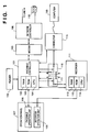
- Fig. 1 is a block diagram showing the configuration of a facsimile apparatus according to an embodiment of the present invention.
- reference numeral 101 denotes a facsimile controller for controlling the overall facsimile apparatus.
- the controller 101 comprises a microprocessor (CPU) 104, a ROM 103 in which various data such as control programs for the CPU 104 and font data are stored, a RAM 102, used as a work area for the CPU 104, for temporarily storing various data and the like, and controls image data input/output and the communication processing.
- CPU microprocessor
- a reader 100 for reading an original image serves as an image data input unit, and a recorder 111 for performing printing based on image data serves as an image data output unit. That is, the reader 100 reads an original conveyed by an original conveying mechanism by a CCD (charge-coupled device) sensor. The read image data is transferred to the recorder 111 which is, e.g. an ink-jet printer, for printing (copying operation). Facsimile image data received via a network controller (NCU) 106 and a modem 105 is decoded and converted into binary image data, then transferred to the recorder 111 which performs printing, based on the data, on a recording medium such as a recording sheet.
- the modem 105 and the NCU 106 controls connection between a communication line N such as a telephone line and data input/output from or to the line N.
- the NCU 106 is connected to a telephone 118 for communication and manual control operation.
- the recorder 111 has an ink-jet head, a recording-sheet conveying mechanism and a printer controller and the like.
- the recorder 111 comprises a CPU 114, a ROM 113 in which various information, such as control programs for the CPU 114 and font data are stored, and a RAM 112 used as a work area for the CPU 114 and further used as a command buffer and a print buffer.
- Numeral 116 and 117 denote switches under the control of the facsimile controller 101. That is, when data inputted from a computer 120 via a connector 115 is directly printed, the switch 116 is connected to the b-terminal and the switch 117 is connected to the d-terminal.
- the RAM 102 of the facsimile controller 101 is used as a print buffer for storing print data transferred from the computer 120, the switch 116 is connected to the a-terminal and the switch 117 is connected to the c-terminal.
- the switch 116 is connected to the a-terminal, and the switch 117 is connected to the c-terminal.
- image data received as a facsimile signal and decoded is transferred from the controller 101 via the switch 117 to the recorder 111 for printing.
- the controller 101 outputs a busy signal indicative of busy-status of the recorder 111 to the computer 120. Accordingly, if the busy signal is ON, the computer 120 connected via the connector 115 determines that the facsimile apparatus cannot be used as a printer.
- the switch 116 is connected to the a-terminal and the switch 117 is connected to the c-terminal.
- Print data transferred from the computer 120 is buffered in the RAM 102 by the controller 101 via the switch 116, then transferred to the recorder 111 via the switch 117 which performs printing based on the print data.
- the switch 117 is connected to the d-terminal and the switch 116 is connected to the b-terminal. Print data from the computer 120 is directly transferred to the recorder 111, via the switches 116 and 117, which performs printing based on the received print data.
- Numeral 107 denotes an operation panel which, as will be described later with reference to Fig. 2, includes a facsimile operation unit 108 and a recorder operation unit 109.
- the facsimile operation unit 108 has a ten-key pad for inputting telephone numbers to specify transmission designations, abbreviated-dialing number keys, various function keys, a mode selection key for switching over the facsimile mode and the printer mode, and a display 200 (Fig. 2) such as an LCD for displaying telephone numbers, time and the like.
- the recorder operation unit 109 has an on-line/off-line switching key, a line-feed (paper feed) key, a form feed key, a print mode key, and operation keys for setting various print modes, and the display 200 for displaying a printing mode or error status, some messages and the like.
- Fig. 2 shows the arrangement of the keys and the construction of the operation panel 107 of the facsimile apparatus of the present embodiment.
- numeral 201 denotes an indicator for indicating the facsimile mode; 202, an indicator for indicating the printer mode; 203, a mode selection key; 205, a function key for setting various functions; and 206, a selection key for setting various modes.
- the indicator 201 is turned on when the facsimile mode is selected.
- the indicator 202 is turned on when the printer mode is selected.
- the mode selection key 203 is used for switching over the facsimile mode and the printer mode. The mode changes alternatively at each pressing of the mode selection key 203.
- the function key 205 is used for setting functions such as broadcasting, direct transmission and confidential transmission.
- the set function is displayed on the display 200.
- the function key 205 is used as an on-line/off-line mode selection key.
- the on-line mode (“ON LINE" on the display 200 is displayed) is for receiving data from the computer 120 and performing printing based on the received data.
- the selection key 206 is used for setting transmission modes such as fine mode and normal mode, and in the printer mode, the selection key 206 is used for setting printing modes such as high-quality printing, normal printing, high-speed printing, etc.
- the selected modes are displayed on the display 200.
- Numeral 207 denotes a stop/clear key; and 208, a start key.
- the stop/clear key 207 is used to stop transmission or clear an error
- the start key 208 is used for instructing the start of transmission or instructing the star of copying operation.
- the start key 208 is used as a paper feed key (LF) or a form feed key (FF).
- the operation panel has a function display area 209 which, in accordance with the respective modes, displays the corresponding functions of those keys 205 to 208. In this manner, the keys 205 to 208 function as a part of the FAX operation unit 108 or the recorder operation unit 109.
- Fig. 4 shows an example of the recorder 111.
- a carriage HC is engaged with a spiral groove 5004 of a lead screw 5005 which rotates via driving force transmission gears 5011 and 5009 interlocking with forward/reverse rotation of a driving motor 5013.
- the carriage has a pin (not shown) and it is reciprocally moved in directions represented by arrows a and b .
- the carriage HC has ink-jet cartridge IJC.
- the ink-jet cartridge IJC integrally comprises a print head IJH and an ink tank IT.
- the print head IJH discharges ink droplets from discharge orifices by changing ink-state using thermal energy.
- a paper bail 5002 presses a recording sheet against a platen 5000 along the moving direction of the carriage.
- Photocouplers 5007 and 5008 are home position detecting members for confirming the existence of lever 5006 of the carriage in this area and changing over the rotational direction of motor 5013.
- a support member 5016 supports a cap member 5022 for capping the front surface of the printing head.
- a suction member 5015 performs suction-restoration of the printing head the inside of the cap member 5022 via a cap inner opening 5023.
- Member 5019 allows a cleaning blade 5017 to move in a back-and-forth direction.
- a main body support plate 5018 supports the member 5019 and the cleaning blade 5017. It is apparent that any well-known cleaning blade is applicable to the printer of the embodiments.
- Numeral 5021 denotes a lever for starting the sucking operation of the suction-restoration. The lever 5021 moves along the movement of a cam 5020 engaged with the carriage.
- a well-known transmission mechanism such as change-over of a clutch controls a driving force from the driving motor.
- a desired processing among capping, cleaning and suction-restoration is executed at its corresponding position by the lead screw 5005.
- the timing of any of these processings is not limited to the printer of the embodiments.
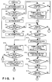
- Fig. 3 shows the control operation by the FAX controller 101 of the facsimile apparatus of the present embodiment.
- the control program for performing this processing is stored in the ROM 103 of the FAX controller 101.
- This facsimile apparatus is set to the facsimile mode when the power is turned on. More specifically, the CPU 104 issues an instruction to set a flag indicative of the facsimile mode in the RAM 102, and the FAX indicator 201 of the display 200 is turned on.
- the keys 205 to 208 on the operation panel 107 are set for the facsimile mode, and the display area 209 displays the respective functions corresponding to the keys in the facsimile mode.
- step S2 the status of the mode selection key 203 on the operation panel 107, i.e., whether or not the mode selection key 203 has been pressed is monitored, and if the key 203 has been pressed, the process proceeds to step S3 where the facsimile mode is changed to the printer mode.
- step S4 whether or not the mode selection key 203 has been pressed is examined. If YES, the process proceeds to step S5 where the facsimile mode is set similarly to step S1.
- step S6 the process proceeds to step S6 where whether or not facsimile starting signals including a CI signal, an original detection signal, a hook-up signal and a signal indicative of the pressing of the start key 208 have been received is monitored. If YES, the process proceeds to step S7 where facsimile operation is started. At this time, the switch 116 is connected to the a-terminal and the switch 117 is connected to the c-terminal, and a busy signal is outputted via the switch 116 and the connector 115 to the computer 120. As the facsimile transmission/reception or copying operation is completed, the process returns to step S2.
- step S4 determines whether or not the mode selection key 203 has been pressed.
- the process proceeds to step S8 where whether or not a printer starting signal has been inputted via the connector 115 is monitored.
- the printer starting signal is, e.g., an initial signal of a centronics interface or a start bit of the RS-232C interface. If the printer starting signal has not been inputted, the process returns to step S3.
- step S8 if it is determined that the printer starting signal has been inputted from the computer 120, the process proceeds to step S9 where whether or not the RAM 102 has a predetermined amount or more empty area is examined. If YES, as the RAM 102 can be used as a print buffer, the process proceeds to step S10. On the other hand, if a predetermined amount or more image data is already stored in the RAM 102 due to reserved transmission or memory reception (temporarily storing received facsimile data) and there is no empty area equal to or more than the predetermined amount, the RAM 102 cannot be used as a print buffer. In this case, the process proceeds to step S16.
- step S10 the availability of the RAM 102 as a FIFO buffer is determined based on its empty area, and end address of the print buffer is determined and is stored into the work area of the RAM 102.
- step S11 the switch 116 is connected to the a-terminal, and the switch 117 is connected to the c-terminal.
- step S12 the RAM 102 is used as the print buffer. That is, print data received via the connector 115 is sequentially stored into the RAM 102. At this time, if the amount of the received data exceeds the memory area (end address) determined in step S10, a busy signal is outputted via the connector 115 to the computer 120.
- step S13 whether or not the recorder 111 is ready is determined. If YES, the process proceeds to step S14 where printing is performed. Then in step S15, it is determined whether or not printing based on all the print data stored in the RAM 102 or based on print data from the computer 120 has been completed. If NO, the process returns to step S12 where the received print data is stored in the RAM 102. If no data has been stored into the RAM 102 for a predetermined period, it is determined that printing has been completed, and the process proceeds to step S5 to repeat the above operation.
- step S9 the process proceeds to step S16, where the switch 116 is connected to the b-terminal and the switch 117 is connected to the d-terminal. Then data transfer for printing is performed between the computer 120 and the recorder 111 via the connector 115.
- step S17 whether or not the mode selection key 203 has been pressed is examined. If YES, the process proceeds to step S18 where the switch 116 is connected to the a-terminal and the switch 117 is connected to the c-terminal, then the process returns to step S5 to clear the printer mode and set the facsimile mode.
- the recorder 111 is performing printing operation, the input from the switch 203 is invalidated until the completion of the printing.
- the current mode may be automatically changed to the facsimile mode.
- Fig. 5 is a flowchart showing the processing when the facsimile apparatus of this embodiment receives a facsimile signal.
- the control program for performing this processing is stored in the ROM 103.
- step S22 whether or not the current mode is the printer mode is examined. If NO, i.e., the facsimile mode has been selected, the process proceeds to step S23 to perform facsimile reception similarly to step S7 in Fig. 3.
- step S22 i.e., the printer mode is selected
- the process proceeds to step S24 where a busy signal is outputted to the computer 120 to set the computer 120 into stand-by status. Preferably, this busy signal is outputted at, e.g., each page break point.
- step S25 whether or not print data from the computer 120 is stored in the RAM 102 is determined, i.e., whether or not a sufficient empty area exists in the RAM 102. If YES, the process proceeds to step S26 where the print data is read out of the RAM 102 and outputted to the recorder 111, to perform printing based on the print data. Then in step S27, the facsimile mode is set, since the used print data is deleted and an empty area for storing the received facsimile data can be made in the RAM 102.
- step S28 similarly to step S7 in Fig. 3, the switch 116 is connected to the a-terminal, and the switch 117 is connected to the c-terminal.
- step S29 facsimile signal reception or printing of decoded data is performed. Steps S29 and S30 are repeated till facsimile reception is completed in step S30. Upon completion of the facsimile reception, the busy signal to the computer 120 is turned off, and the current mode is changed from the facsimile mode to the printer mode.
- the determination of the completion of printing is made if no data has been stored into the RAM for a predetermined period. However, this determination may be made in accordance with key-input from the mode selection key 203.
- a busy signal may be outputted to the computer 120 to set the computer 120 into stand-by status. Then all the print data in the RAM 120 may be outputted to the recorder 111 to perform printing, thereafter, facsimile reception in accordance with the received facsimile signal may be performed.
- the memory (RAM 102) of the facsimile controller 101 can be used as a print buffer, which enables high-speed reception of print data from the computer 120, further enables effective utilization of hardware resource of the facsimile apparatus.
- the present invention can be applied to a system constituted by a plurality of devices, or to an apparatus comprising a single device. Furthermore, the invention is applicable also to a case where the object of the invention is attained by supplying a program to a system or apparatus.
- the recorder 111 is a printing apparatus of, among the ink-jet printing methods, especially a type having an arrangement that heat energy is utilized to form a flying fluid droplet so as to perform the recording operation.
- the basic structure disclosed in, for example, U.S. Patent No. 4,723,129 or 4,740,796 be employed.
- the aforesaid method can be adapted to both so-called on-demand type apparatus and continuous type apparatus.
- a satisfactory effect can be obtained when the on-demand type apparatus is employed because of the structure is arranged in such a manner that one or more drive signals, which rapidly raise the temperature of an electricity-to-heat converter disposed to face a sheet or a fluid passage which holds the fluid (ink) to a level higher than levels at which nuclear boiling takes place are applied to the electricity-to-heat converter so as to generate heat energy in the electricity-to-heat converter and to cause the heat effecting surface of the printing head to take place film boiling so that bubbles can be formed in the fluid (ink) to correspond to the one or more drive signals.
- the enlargement/contraction of the bubble will cause the fluid (ink) to be discharged through a discharging opening so that one or more droplets are formed.
- a pulse shape drive signal is employed, the bubble can be enlarged/contracted immediately and properly, causing a further preferred effect to be obtained because the fluid (ink) can be discharged while revealing excellent responsiveness.
- the following structures may be employed: a structure having an arrangement that a common slit is formed to serve as a discharge section of a plurality of electricity-to-heat converters and disclosed in Japanese Patent Laid-Open No. 59-123670; and a structure disclosed in Japanese Patent Laid-Open No. 59-138461 in which an opening for absorbing pressure waves of heat energy is disposed to correspond to the discharge section.
- a full-line type printing head having a length capable of covering the width of the widest recording medium which can be recorded by the recording apparatus, a structure having the width by combining a plurality of printing heads or a structure having a sole integrated printing head and disclosed in any of the aforesaid specifications may be employed.
- a chip type printing head which can be electrically connected to the body of the apparatus or to which ink can be supplied from the body of the apparatus when it is fastened to the body of the apparatus may be employed. Furthermore, a cartridge printing head having an ink tank integrally formed with the printing head may be employed.
- the printing head restoring means and the auxiliary means provided as the component of the present invention because the effect of the present invention can be further stabled.
- a printing head capping means a cleaning means, a pressurizing or suction means, an electricity-to-heat converter, an another heating element or a sub-heating means constituted by combining them and a sub-emitting mode in which an emitting is performed independently from the printing emitting in order to stably perform the printing operation.
- ink which solidifies at the room temperature or lower and as well as softened at the room temperature, or ink in the form of a fluid at the room temperature or ink which is formed into a fluid when the recording signal is supplied may be employed because the aforesaid ink jet recording method is ordinarily arranged in such a manner that the temperature of ink is controlled in a range from 30°C or higher and 70°C or lower so as to make the viscosity of the ink to be included in a stable discharge range.
- ink of the following types can be adapted to the present invention: ink which liquefies when heat energy is supplied in response to the recording signal so as to be discharged in the form of fluid ink, the aforesaid ink being exemplified by ink, the temperature rise due to supply of the heat energy is positively prevented by utilizing the temperature rise as energy of state change from the solid state to the liquid state; and ink which solidifies when it is allowed to stand to prevent ink evaporation. Furthermore, ink which first liquefies when supplied with heat energy may be adapted to the present invention.
- the ink may be of a type which is held as fluid or solid material in a recess of a porous sheet or a through hole at a position facing the electricity-to-heat converter as disclosed in Japanese Patent Laid-Open No. 54-56847 or Japanese Patent Laid-Open No. 60-71260. It is the most preferred way for the ink to be adapted to the aforesaid film boiling method.
- the recorder according to the present invention may be in the form of a copying apparatus combined with a reader or the like, or a facsimile apparatus having a transmission/receiving function as well as the integrated or independent apparatus serving as image output terminative equipment of information processing apparatus such as the aforesaid word processor or the computer.
- the recording method is applicable to an ink-jet printing method utilizing a piezoelectric device as well as the ink-jet printing method utilizing thermal energy.
Landscapes
- Engineering & Computer Science (AREA)
- General Engineering & Computer Science (AREA)
- Multimedia (AREA)
- Signal Processing (AREA)
- Computing Systems (AREA)
- Facsimiles In General (AREA)
- Record Information Processing For Printing (AREA)
- Facsimile Scanning Arrangements (AREA)
- Accessory Devices And Overall Control Thereof (AREA)
Applications Claiming Priority (2)
| Application Number | Priority Date | Filing Date | Title |
|---|---|---|---|
| JP22620293A JP3507102B2 (ja) | 1993-09-10 | 1993-09-10 | ファクシミリ装置とその印刷制御方法 |
| JP226202/93 | 1993-09-10 |
Publications (2)
| Publication Number | Publication Date |
|---|---|
| EP0643525A1 true EP0643525A1 (de) | 1995-03-15 |
| EP0643525B1 EP0643525B1 (de) | 1999-03-31 |
Family
ID=16841495
Family Applications (1)
| Application Number | Title | Priority Date | Filing Date |
|---|---|---|---|
| EP94306627A Expired - Lifetime EP0643525B1 (de) | 1993-09-10 | 1994-09-09 | Faksimilegerät und dazugehöriges Verfahren zur Drucksteuerung |
Country Status (4)
| Country | Link |
|---|---|
| US (2) | US5621540A (de) |
| EP (1) | EP0643525B1 (de) |
| JP (1) | JP3507102B2 (de) |
| DE (1) | DE69417495T2 (de) |
Families Citing this family (20)
| Publication number | Priority date | Publication date | Assignee | Title |
|---|---|---|---|---|
| JP3507102B2 (ja) * | 1993-09-10 | 2004-03-15 | キヤノン株式会社 | ファクシミリ装置とその印刷制御方法 |
| JP3376052B2 (ja) * | 1993-11-26 | 2003-02-10 | キヤノン株式会社 | ファクシミリ装置及びその制御方法 |
| US6775021B1 (en) * | 1993-11-26 | 2004-08-10 | Canon Kabushiki Kaisha | Data communication apparatus for receiving and recording data and having means for adding a predetermined mark and a time of reception to the recorded data |
| JP3296920B2 (ja) * | 1994-03-15 | 2002-07-02 | 京セラミタ株式会社 | ファクシミリ装置 |
| JP3665877B2 (ja) * | 1994-03-24 | 2005-06-29 | 株式会社リコー | 複合機 |
| JP3467112B2 (ja) * | 1995-03-24 | 2003-11-17 | ブラザー工業株式会社 | 画像形成装置 |
| US6082847A (en) * | 1995-09-01 | 2000-07-04 | Canon Kabushiki Kaisha | Image system with informing means |
| US5898824A (en) * | 1995-11-10 | 1999-04-27 | Brother Kogyo Kabushiki Kaisha | Facsimile machine for use in combination with PC |
| US5802261A (en) * | 1995-11-14 | 1998-09-01 | Ricoh Company, Ltd. | Facsimile apparatus improved printer, scanner and communication functions |
| JP4147593B2 (ja) * | 1996-05-20 | 2008-09-10 | ブラザー工業株式会社 | 多機能周辺装置および記憶媒体 |
| JP3806987B2 (ja) * | 1996-08-26 | 2006-08-09 | ブラザー工業株式会社 | 多機能周辺装置 |
| JPH1063518A (ja) * | 1996-08-26 | 1998-03-06 | Brother Ind Ltd | 情報処理装置、および記憶媒体 |
| JP3666770B2 (ja) * | 1996-11-26 | 2005-06-29 | シチズン時計株式会社 | 携帯用プリンタ・ファクシミリ複合装置 |
| JPH10294817A (ja) | 1997-04-18 | 1998-11-04 | Matsushita Graphic Commun Syst Inc | 画像記録装置及びこれを用いた送信方法 |
| JPH11122410A (ja) * | 1997-10-17 | 1999-04-30 | Minolta Co Ltd | 画像出力装置 |
| US7262873B1 (en) | 2000-07-05 | 2007-08-28 | Lexmark International, Inc. | Photoprinter access to remote data |
| JP3898987B2 (ja) * | 2001-07-30 | 2007-03-28 | 株式会社リコー | 画像形成装置、該装置に用いられる画像転送制御方法、およびその方法をコンピュータに実行させるプログラム、並びにそのプログラムを記録したコンピュータ読み取り可能な記録媒体 |
| JP4133526B2 (ja) * | 2003-04-11 | 2008-08-13 | シャープ株式会社 | 画像形成方法、画像形成システム及び画像形成装置 |
| JP4079159B2 (ja) * | 2005-05-19 | 2008-04-23 | コニカミノルタビジネステクノロジーズ株式会社 | ファクシミリ装置、ファクシミリ送信処理方法及び同受信処理方法 |
| JP4281736B2 (ja) * | 2005-11-30 | 2009-06-17 | ブラザー工業株式会社 | ファクシミリ装置 |
Citations (5)
| Publication number | Priority date | Publication date | Assignee | Title |
|---|---|---|---|---|
| US4991200A (en) * | 1987-09-29 | 1991-02-05 | Paul Lin | Interface device for the intercommunication of a computer and a fax machine |
| US5072303A (en) * | 1989-12-29 | 1991-12-10 | Morton Silverberg | Combined printer and facsimile apparatus which scans using different scan rates and dot sizes |
| EP0477947A2 (de) * | 1990-09-28 | 1992-04-01 | Hewlett-Packard Company | Schalter zur gemeinsamen Benutzung eines Peripheriegeräts |
| EP0519253A2 (de) * | 1991-06-18 | 1992-12-23 | Siemens Aktiengesellschaft | Verfahren zum Realisieren eines Seitendruckers für einen Personalcomputer mittels eines Telefaxgerätes |
| JPH0563932A (ja) * | 1991-08-30 | 1993-03-12 | Canon Inc | フアクシミリ装置 |
Family Cites Families (8)
| Publication number | Priority date | Publication date | Assignee | Title |
|---|---|---|---|---|
| JP2577553B2 (ja) * | 1987-01-28 | 1997-02-05 | キヤノン株式会社 | 端末装置 |
| JP2881798B2 (ja) * | 1989-03-04 | 1999-04-12 | ミノルタ株式会社 | 受信装置 |
| JP2910116B2 (ja) * | 1990-01-25 | 1999-06-23 | ブラザー工業株式会社 | インターフェース付ファクシミリ装置 |
| US5311327A (en) * | 1990-11-10 | 1994-05-10 | Minolta Camera Kabushiki Kaisha | Facsimile machine including image memory capable of efficient transmission/reception |
| ATE202251T1 (de) * | 1991-08-19 | 2001-06-15 | Oki America Inc | Multifunktionelles dokumentenverarbeitungssystem |
| JP2952111B2 (ja) * | 1992-07-09 | 1999-09-20 | キヤノン株式会社 | データ制御装置 |
| JP3507102B2 (ja) * | 1993-09-10 | 2004-03-15 | キヤノン株式会社 | ファクシミリ装置とその印刷制御方法 |
| US5608546A (en) * | 1994-03-11 | 1997-03-04 | Mita Industrial Co., Ltd. | Data communications apparatus having a computer modem function |
-
1993
- 1993-09-10 JP JP22620293A patent/JP3507102B2/ja not_active Expired - Fee Related
-
1994
- 1994-09-09 EP EP94306627A patent/EP0643525B1/de not_active Expired - Lifetime
- 1994-09-09 DE DE69417495T patent/DE69417495T2/de not_active Expired - Fee Related
- 1994-09-09 US US08/301,433 patent/US5621540A/en not_active Expired - Fee Related
-
1997
- 1997-01-28 US US08/789,872 patent/US5778163A/en not_active Expired - Fee Related
Patent Citations (5)
| Publication number | Priority date | Publication date | Assignee | Title |
|---|---|---|---|---|
| US4991200A (en) * | 1987-09-29 | 1991-02-05 | Paul Lin | Interface device for the intercommunication of a computer and a fax machine |
| US5072303A (en) * | 1989-12-29 | 1991-12-10 | Morton Silverberg | Combined printer and facsimile apparatus which scans using different scan rates and dot sizes |
| EP0477947A2 (de) * | 1990-09-28 | 1992-04-01 | Hewlett-Packard Company | Schalter zur gemeinsamen Benutzung eines Peripheriegeräts |
| EP0519253A2 (de) * | 1991-06-18 | 1992-12-23 | Siemens Aktiengesellschaft | Verfahren zum Realisieren eines Seitendruckers für einen Personalcomputer mittels eines Telefaxgerätes |
| JPH0563932A (ja) * | 1991-08-30 | 1993-03-12 | Canon Inc | フアクシミリ装置 |
Non-Patent Citations (2)
| Title |
|---|
| H.SENDLINGER: "ÜBERTRAGEN, DRUCKEN UND SCANNEN MIT EINEM GERÄT", TELCOM REPORT, vol. 25, no. 1, January 1992 (1992-01-01), MÜNCHEN, DE, pages 48 - 50, XP000259065 * |
| PATENT ABSTRACTS OF JAPAN vol. 17, no. 380 (E - 1399) 16 July 1993 (1993-07-16) * |
Also Published As
| Publication number | Publication date |
|---|---|
| EP0643525B1 (de) | 1999-03-31 |
| US5621540A (en) | 1997-04-15 |
| DE69417495D1 (de) | 1999-05-06 |
| DE69417495T2 (de) | 1999-09-16 |
| US5778163A (en) | 1998-07-07 |
| JPH0787272A (ja) | 1995-03-31 |
| JP3507102B2 (ja) | 2004-03-15 |
Similar Documents
| Publication | Publication Date | Title |
|---|---|---|
| US5621540A (en) | Facsimile apparatus and printing control method therefor | |
| US5832190A (en) | Image recording apparatus with reliable, efficient and power-saving stand-by state | |
| US5604597A (en) | Image communication device with selectably variable resolution control and scan speed controlled by the selected resolution | |
| US5689289A (en) | Image recording apparatus | |
| US6111656A (en) | Image communicating apparatus | |
| EP0643526B1 (de) | Bildaufzeichnungsgerät und Betriebsartumschaltungsverfahren in diesem Gerät | |
| US6426805B1 (en) | Image recording apparatus and method therefor | |
| US6880905B2 (en) | Image printing apparatus and control method therefor | |
| JPH07154589A (ja) | データ処理装置及び記録装置 | |
| EP0608880B1 (de) | Bilderzeugungsgerät | |
| US7532344B2 (en) | Information processing apparatus | |
| EP0613287A1 (de) | Verfahren und Gerät zur Bildübertragung | |
| EP1236572B1 (de) | Druckvorrichtung und Verfahren zur Auswahl der charakteristischen Druckkopfdaten | |
| US5877782A (en) | Image recording apparatus | |
| JP3402684B2 (ja) | ファクシミリ装置 | |
| JPH07131614A (ja) | 画像記録方法及び装置及び該装置を用いたファクシミリ装置 | |
| EP0616896B1 (de) | Bildaufzeichnungsgerät | |
| JP3234067B2 (ja) | 画像記録装置と該装置におけるモード切替方法 | |
| JP3347474B2 (ja) | ファクシミリ装置 | |
| EP0443247A2 (de) | Bildübertragungsgerät | |
| JP2002254612A (ja) | 画像記録装置および画像記録方法 | |
| JPH07327117A (ja) | 画像記録装置及びその制御方法 | |
| JPH08181803A (ja) | インクジェットファクシミリ装置 | |
| JPH06284238A (ja) | 画像記録装置 | |
| KR20000015724A (ko) | 외부 전화기를 통한 인쇄 수직 정렬 조정 방법 |
Legal Events
| Date | Code | Title | Description |
|---|---|---|---|
| PUAI | Public reference made under article 153(3) epc to a published international application that has entered the european phase |
Free format text: ORIGINAL CODE: 0009012 |
|
| AK | Designated contracting states |
Kind code of ref document: A1 Designated state(s): DE ES FR GB IT |
|
| 17P | Request for examination filed |
Effective date: 19950728 |
|
| 17Q | First examination report despatched |
Effective date: 19970624 |
|
| GRAG | Despatch of communication of intention to grant |
Free format text: ORIGINAL CODE: EPIDOS AGRA |
|
| GRAG | Despatch of communication of intention to grant |
Free format text: ORIGINAL CODE: EPIDOS AGRA |
|
| GRAG | Despatch of communication of intention to grant |
Free format text: ORIGINAL CODE: EPIDOS AGRA |
|
| GRAH | Despatch of communication of intention to grant a patent |
Free format text: ORIGINAL CODE: EPIDOS IGRA |
|
| GRAH | Despatch of communication of intention to grant a patent |
Free format text: ORIGINAL CODE: EPIDOS IGRA |
|
| GRAA | (expected) grant |
Free format text: ORIGINAL CODE: 0009210 |
|
| AK | Designated contracting states |
Kind code of ref document: B1 Designated state(s): DE ES FR GB IT |
|
| PG25 | Lapsed in a contracting state [announced via postgrant information from national office to epo] |
Ref country code: IT Free format text: LAPSE BECAUSE OF FAILURE TO SUBMIT A TRANSLATION OF THE DESCRIPTION OR TO PAY THE FEE WITHIN THE PRE;WARNING: LAPSES OF ITALIAN PATENTS WITH EFFECTIVE DATE BEFORE 2007 MAY HAVE OCCURRED AT ANY TIME BEFORE 2007. THE CORRECT EFFECTIVE DATE MAY BE DIFFERENT FROM THE ONE RECORDED.SCRIBED TIME-LIMIT Effective date: 19990331 Ref country code: ES Free format text: THE PATENT HAS BEEN ANNULLED BY A DECISION OF A NATIONAL AUTHORITY Effective date: 19990331 |
|
| REF | Corresponds to: |
Ref document number: 69417495 Country of ref document: DE Date of ref document: 19990506 |
|
| ET | Fr: translation filed | ||
| PLBE | No opposition filed within time limit |
Free format text: ORIGINAL CODE: 0009261 |
|
| STAA | Information on the status of an ep patent application or granted ep patent |
Free format text: STATUS: NO OPPOSITION FILED WITHIN TIME LIMIT |
|
| 26N | No opposition filed | ||
| REG | Reference to a national code |
Ref country code: GB Ref legal event code: IF02 |
|
| PGFP | Annual fee paid to national office [announced via postgrant information from national office to epo] |
Ref country code: FR Payment date: 20030919 Year of fee payment: 10 Ref country code: DE Payment date: 20030919 Year of fee payment: 10 |
|
| PGFP | Annual fee paid to national office [announced via postgrant information from national office to epo] |
Ref country code: GB Payment date: 20040826 Year of fee payment: 11 |
|
| PG25 | Lapsed in a contracting state [announced via postgrant information from national office to epo] |
Ref country code: DE Free format text: LAPSE BECAUSE OF NON-PAYMENT OF DUE FEES Effective date: 20050401 |
|
| PG25 | Lapsed in a contracting state [announced via postgrant information from national office to epo] |
Ref country code: FR Free format text: LAPSE BECAUSE OF NON-PAYMENT OF DUE FEES Effective date: 20050531 |
|
| REG | Reference to a national code |
Ref country code: FR Ref legal event code: ST |
|
| PG25 | Lapsed in a contracting state [announced via postgrant information from national office to epo] |
Ref country code: GB Free format text: LAPSE BECAUSE OF NON-PAYMENT OF DUE FEES Effective date: 20050909 |
|
| GBPC | Gb: european patent ceased through non-payment of renewal fee |
Effective date: 20050909 |