EP0643998A2 - Verfahren und Vorrichtung zum Beschichten - Google Patents
Verfahren und Vorrichtung zum Beschichten Download PDFInfo
- Publication number
- EP0643998A2 EP0643998A2 EP94306572A EP94306572A EP0643998A2 EP 0643998 A2 EP0643998 A2 EP 0643998A2 EP 94306572 A EP94306572 A EP 94306572A EP 94306572 A EP94306572 A EP 94306572A EP 0643998 A2 EP0643998 A2 EP 0643998A2
- Authority
- EP
- European Patent Office
- Prior art keywords
- coating
- wires
- curing
- rollers
- elongate members
- Prior art date
- Legal status (The legal status is an assumption and is not a legal conclusion. Google has not performed a legal analysis and makes no representation as to the accuracy of the status listed.)
- Granted
Links
- 238000000576 coating method Methods 0.000 title claims abstract description 118
- 239000011248 coating agent Substances 0.000 title claims abstract description 114
- 238000000034 method Methods 0.000 title claims abstract description 34
- 238000010438 heat treatment Methods 0.000 claims description 19
- 238000001816 cooling Methods 0.000 claims description 17
- 239000007787 solid Substances 0.000 claims description 10
- 239000002904 solvent Substances 0.000 claims description 6
- 238000010924 continuous production Methods 0.000 claims 1
- 239000000843 powder Substances 0.000 description 15
- XLYOFNOQVPJJNP-UHFFFAOYSA-N water Substances O XLYOFNOQVPJJNP-UHFFFAOYSA-N 0.000 description 9
- 239000002184 metal Substances 0.000 description 6
- 238000010791 quenching Methods 0.000 description 5
- 150000001875 compounds Chemical class 0.000 description 4
- 238000005260 corrosion Methods 0.000 description 4
- 230000007797 corrosion Effects 0.000 description 4
- 238000003780 insertion Methods 0.000 description 4
- 230000037431 insertion Effects 0.000 description 4
- 239000002245 particle Substances 0.000 description 4
- 230000000171 quenching effect Effects 0.000 description 4
- 238000012360 testing method Methods 0.000 description 4
- 239000000463 material Substances 0.000 description 3
- 229920000728 polyester Polymers 0.000 description 3
- 239000007921 spray Substances 0.000 description 3
- 239000002023 wood Substances 0.000 description 3
- 238000009825 accumulation Methods 0.000 description 2
- 238000005452 bending Methods 0.000 description 2
- 238000005520 cutting process Methods 0.000 description 2
- 238000012545 processing Methods 0.000 description 2
- 238000011084 recovery Methods 0.000 description 2
- 238000000926 separation method Methods 0.000 description 2
- 239000004593 Epoxy Substances 0.000 description 1
- JOYRKODLDBILNP-UHFFFAOYSA-N Ethyl urethane Chemical compound CCOC(N)=O JOYRKODLDBILNP-UHFFFAOYSA-N 0.000 description 1
- 239000000020 Nitrocellulose Substances 0.000 description 1
- 239000004677 Nylon Substances 0.000 description 1
- 239000004698 Polyethylene Substances 0.000 description 1
- FJWGYAHXMCUOOM-QHOUIDNNSA-N [(2s,3r,4s,5r,6r)-2-[(2r,3r,4s,5r,6s)-4,5-dinitrooxy-2-(nitrooxymethyl)-6-[(2r,3r,4s,5r,6s)-4,5,6-trinitrooxy-2-(nitrooxymethyl)oxan-3-yl]oxyoxan-3-yl]oxy-3,5-dinitrooxy-6-(nitrooxymethyl)oxan-4-yl] nitrate Chemical compound O([C@@H]1O[C@@H]([C@H]([C@H](O[N+]([O-])=O)[C@H]1O[N+]([O-])=O)O[C@H]1[C@@H]([C@@H](O[N+]([O-])=O)[C@H](O[N+]([O-])=O)[C@@H](CO[N+]([O-])=O)O1)O[N+]([O-])=O)CO[N+](=O)[O-])[C@@H]1[C@@H](CO[N+]([O-])=O)O[C@@H](O[N+]([O-])=O)[C@H](O[N+]([O-])=O)[C@H]1O[N+]([O-])=O FJWGYAHXMCUOOM-QHOUIDNNSA-N 0.000 description 1
- 150000001408 amides Chemical class 0.000 description 1
- 230000033228 biological regulation Effects 0.000 description 1
- 239000006227 byproduct Substances 0.000 description 1
- 239000011247 coating layer Substances 0.000 description 1
- 230000001276 controlling effect Effects 0.000 description 1
- 238000005538 encapsulation Methods 0.000 description 1
- 238000001704 evaporation Methods 0.000 description 1
- 230000008020 evaporation Effects 0.000 description 1
- 238000010304 firing Methods 0.000 description 1
- 239000003292 glue Substances 0.000 description 1
- 230000005484 gravity Effects 0.000 description 1
- 150000002500 ions Chemical class 0.000 description 1
- 238000005304 joining Methods 0.000 description 1
- 239000010410 layer Substances 0.000 description 1
- 230000014759 maintenance of location Effects 0.000 description 1
- 238000004519 manufacturing process Methods 0.000 description 1
- 239000000203 mixture Substances 0.000 description 1
- 229920001220 nitrocellulos Polymers 0.000 description 1
- 229940079938 nitrocellulose Drugs 0.000 description 1
- 229920001778 nylon Polymers 0.000 description 1
- 239000003960 organic solvent Substances 0.000 description 1
- 238000004806 packaging method and process Methods 0.000 description 1
- 238000012856 packing Methods 0.000 description 1
- -1 polyethylene Polymers 0.000 description 1
- 229920000573 polyethylene Polymers 0.000 description 1
- 230000001105 regulatory effect Effects 0.000 description 1
- 238000009877 rendering Methods 0.000 description 1
- 239000011347 resin Substances 0.000 description 1
- 229920005989 resin Polymers 0.000 description 1
- 238000005096 rolling process Methods 0.000 description 1
- 238000007790 scraping Methods 0.000 description 1
- 238000010008 shearing Methods 0.000 description 1
- 238000000935 solvent evaporation Methods 0.000 description 1
- 238000003860 storage Methods 0.000 description 1
Images



Classifications
-
- B—PERFORMING OPERATIONS; TRANSPORTING
- B05—SPRAYING OR ATOMISING IN GENERAL; APPLYING FLUENT MATERIALS TO SURFACES, IN GENERAL
- B05D—PROCESSES FOR APPLYING FLUENT MATERIALS TO SURFACES, IN GENERAL
- B05D7/00—Processes, other than flocking, specially adapted for applying liquids or other fluent materials to particular surfaces or for applying particular liquids or other fluent materials
- B05D7/20—Processes, other than flocking, specially adapted for applying liquids or other fluent materials to particular surfaces or for applying particular liquids or other fluent materials to wires
-
- B—PERFORMING OPERATIONS; TRANSPORTING
- B05—SPRAYING OR ATOMISING IN GENERAL; APPLYING FLUENT MATERIALS TO SURFACES, IN GENERAL
- B05D—PROCESSES FOR APPLYING FLUENT MATERIALS TO SURFACES, IN GENERAL
- B05D1/00—Processes for applying liquids or other fluent materials
- B05D1/02—Processes for applying liquids or other fluent materials performed by spraying
- B05D1/04—Processes for applying liquids or other fluent materials performed by spraying involving the use of an electrostatic field
- B05D1/06—Applying particulate materials
-
- Y—GENERAL TAGGING OF NEW TECHNOLOGICAL DEVELOPMENTS; GENERAL TAGGING OF CROSS-SECTIONAL TECHNOLOGIES SPANNING OVER SEVERAL SECTIONS OF THE IPC; TECHNICAL SUBJECTS COVERED BY FORMER USPC CROSS-REFERENCE ART COLLECTIONS [XRACs] AND DIGESTS
- Y10—TECHNICAL SUBJECTS COVERED BY FORMER USPC
- Y10T—TECHNICAL SUBJECTS COVERED BY FORMER US CLASSIFICATION
- Y10T29/00—Metal working
- Y10T29/49—Method of mechanical manufacture
- Y10T29/49826—Assembling or joining
- Y10T29/49906—Metal deforming with nonmetallic bonding
Definitions
- This invention relates generally to coating and more particularly to a method and apparatus for providing a continuous in line process for coating elongate members used for mass producing coated fasteners, such as staples or nails, arranged in a strip or block for ease of handling and packaging as well as loading into a driving tool.
- a coating is utilised which is composed of 100% dry solids, is virtually free of solvent emissions when applied and during curing and covers substantially the entire exterior surface of each fastener. The coating protects the fastener against corrosion, adheres successive fasteners together into a strip or block and provides improved retention of the fastener when driven into a desired surface.
- Coating the exterior surfaces of fasteners frequently is desirable to protect fasteners from corrosion.
- Such coatings also are utilised to adhere a plurality of fasteners together into a strip or block for ease of handling with fastener driving or dispensing devices, such as a staple gun, nail gun or the like.
- wire staples or nails frequently are provided successively arranged and secured in a strip.
- Each strip contains a desired number of staples or nails which are adhered together by the coating and enable easy insertion of the strip within a magazine of a staple or nail gun.
- the coating holds the fasteners together in a strip yet is thin enough to enable insertion of the fasteners within the staple or nail gun and allow for separation of the individual fasteners from the strip upon firing of the gun.
- Such coatings typically are composed of a nitro-cellulose resin dissolved in an organic solvent which is applied to the fasteners. After the solvent is evaporated, the coating remains adhered to the fastener. During solvent evaporation, the coating can be utilised to adhere successive fasteners into a strip.
- An example of such a coating and process is illustrated in U.S. Patent No. 3,813,985.
- a method of providing a coating on the surfaces of a plurality of elongate members comprises the steps of:
- the method is particularly useful to provide such a coating on a plurality of continuous wires which are formed into fasteners, such as staples or nails, after curing.
- the coating additionally functions to adhere successive wires together so that a strip or block of wires are provided which is easier to form the wires into fasteners, package for shipping and storage and load into a driving tool or gun.
- the apparatus utilised to perform the method of the invention is designated generally by the reference numeral 10.
- the method substantially includes the following steps.
- a continuous supply of a plurality of wire strands 12 is provided from stock, the wire 12 typically being wound on rolls (not illustrated).
- the wires 12 are arranged in successive side by side parallel engagement and are fed to a coating booth 14. While moving through the coating booth 14, the exterior surfaces of each wire 12 are provided with a 100% dry solids powder coating which preferably is a powder coating provided electrostatically as described below.
- top and bottom surfaces of the wires 12 are scraped or wiped by a set of wiping rollers 16 which remove excess coating from those surfaces while maintaining a thin coating on the top and bottom surfaces of the wires 12.
- the wiping rollers 16 also compact the powder coating between the parallel wires 12, as Figure 3 illustrates, for reasons described herein-after.
- the wires 12 are conveyed for curing which preferably includes heating in an oven 18 and subsequent cooling in a cooling chamber 20 or the like.
- the curing depends upon the type of coating utilised and can vary.
- the curing enables the coating to flow about the exterior surface of the wires 12, adhere the coating to the wires 12 and adhere the wires 12 together into a continuous band.
- Figure 3 illustrates a band of wires 12 adhered together by the present process.
- the adhered band of wires 12 is shaped into a desired form by a forming machine 22, which typically includes cutting and bending, to provide a strip of fasteners, such as staples or nails.
- a forming machine 22 typically includes cutting and bending, to provide a strip of fasteners, such as staples or nails.
- FIG 4 illustrates, after a fastener is removed from the strip the majority of coating is concentrated on its corners. A thin layer of coating remains on the top and bottom surfaces as well as the arcuate side surfaces.
- the coating can be a powder coating, a U.V. cured coating or a water based coating.
- a powder coating is utilised which can be polyester, polyethylene, nylon, epoxy or other material so long as it functions as described herein.
- That polyester powder coating is composed of 100% dry solids, is applied electrostatically and is cured by heating and subsequent cooling. It is to be understood, however, that the particular coating as well as its application and curing can vary so long as the desired results are obtained, including virtually eliminating the production of harmful volatile compounds during any stage of the process.
- the above described process is accomplished in a continuous in line operation where the wires 12 are advanced at a constant pre-determined speed and tension provided by one or more drive motors (not illustrated).
- the speed and tension of the wires 12 readily can be adjusted to accommodate different types and sizes of wires 12, different coatings, or both.
- a plurality of wires 12 preferably are fed from rolls of stock in successive side by side engagement to the coating booth 14 illustrated in detail in Figure 2.
- the wires 12 preferably are made of a conductive metal and are somewhat oval in cross sectional configuration to provide substantially flat top and bottom surfaces and arcuate opposite sides as illustrated in Figure 3 and 4.
- the particular material, shape and size of the wires 12, however, can vary.
- the wires 12 are coated with a powder coating composed of 100% dry solids.
- the powder coating preferably is applied using an electrostatic process where powder particles are electrostatically charged as they exit spray guns 24, one each on the top and bottom of the coating booth 14 as illustrated in Figure 1.
- the number, position and type of spray guns 24, however, can vary.
- the charged particles exit the spray guns 24, they form a particle cloud ion field 26 through which the grounded wires 12 are passed.
- the charged powder particles stick to the exposed surfaces of the grounded wires 12 which then are conveyed for further processing.
- Grounding of the wires 12 is provided by contact of the wires 12 with metal supports (not illustrated) positioned at either end of the apparatus 10, or by some other means.
- a pair of wiping or scraping rollers 16 are provided which are illustrated in detail in Figures 7 and 8.
- the wiping rollers 16 preferably are driven by one or more motors (not illustrated) and are rotated in a direction opposite to the direction of travel of the wires 12.
- the wiping rollers 16 can be replaced with some other structure so long as the desired wiping is provided.
- each wiping roller 16 preferably includes a substantially solid core member 28 and an outer softer sleeve member 20.
- the core 28 is made of metal and the sleeve 30 is made of urethane, but the particular materials can vary, including providing solid metal rollers 16, so long as the wiping rollers 16 function as described herein.
- the wiping rollers 16 function to maintain a desired amount of coating on the top and bottom surfaces of the wires 12 and to direct coating into recesses between the corners of the wires 12.
- the position of the wiping rollers 16 and their reverse direction of rotation does not diminish the speed of the wires 12.
- the wiping rollers 16 enhance compacting the powder coating between wires 12 and do not remove all of the coating from the flat top and bottom surfaces of the wires 12.
- the rollers 16 only remove excess coating to provide a finished outside perimeter of the wire 12 which readily and consistently can be accepted by a magazine and bore of a driving tool without jamming.
- the position of the wiping rollers 16 can be adjusted to vary the thickness of the coating on the wires 12.
- each wiping roller 16 can include a scraper blade 32 and one or more vacuum heads 34.
- the scraper blades 32 scrape excess coating from the surface of the sleeves 30 and the vacuum heads 34 convey the excess coating through a hose 36 for re-cycling.
- air jets (not illustrated) can be utilised in place of the scraper blades 32 and vacuum heads 34 to blow excess coating from the wiping rollers 16 into a recovery container or system.
- the scraper blades 32 and vacuum heads 34 are mounted for automatic adjustment on a support 38.
- the support 38 functions similar to an idler assembly to accommodate any changes in diameter of the wiping rollers 16.
- each support 38 includes an elongate bar 40 which spans a respective wiping roller 16, is mounted on opposite ends for angular adjustment with respect to the wiper roller 16 and mounts both the scraper blade 32 and the vacuum heads 34.
- a weight 42 is mounted to the bar 40 through an arm assembly 44 and preferably is regulated by a spring 46.
- the spring 46 simply can be attached to the weight 42, as illustrated with the top wiping roller 16, or can be provided for engagement with a portion of the arm assembly 44, as illustrated with the bottom wiping roller 16. Alternatively, the spring 46 can be eliminated.
- the weight 42 relies on the force of the spring 46 and/or gravity to provide the engagement force between the scraper blade 32 and wiping rollers 16 which can be adjusted by proper positioning of the weight 42 on the arm assembly 44. It is to be understood, however, that any type of assembly can be utilised to adjust the wiper rollers 16 during use without departing from the teachings of the present invention, including any type of automatic control system.
- FIG. 1 illustrates, after the wires 12 have passed through the wiper rollers 16, they are conveyed for curing, preferably in an oven 18, such as an infra-red oven. Due to the composition of the powder coating, heating of the coated wires 12 in the oven 18 to a desired temperature enables the coating to flow about the exterior surfaces of the wires 12 to ensure substantially complete coverage and adhesion upon cooling.
- an oven 18 such as an infra-red oven. Due to the composition of the powder coating, heating of the coated wires 12 in the oven 18 to a desired temperature enables the coating to flow about the exterior surfaces of the wires 12 to ensure substantially complete coverage and adhesion upon cooling.
- the coating is virtually free of solvent emissions during application, curing and any other part of the process. This is highly desirable in view of the ever increasing government restrictions against the release of volatile compounds into the atmosphere. It has been determined that emissions of the present process are approximately 1%, with 98% of that amount being moisture.
- the wires 12 are conveyed into the cooling chamber 20 where they preferably are water cooled, but curing with air or any other gas can be provided.
- the coating hardens and the wires 12, which are arranged substantially parallel in successive side by side engagement, are adhered together laterally by the coating alone to form a continuous band of wires as illustrated in Figure 3.
- the number of wires 12 included in the band is between 50 to 100 and depends only on the size desired for the finished band.
- the band of adhered wires 12 then is conveyed for forming into a desired strip or block of adhered fasteners by some type of forming machine 22.
- the band is formed to provide a strip of staples for insertion into a staple gun (not illustrated).
- the band of wires 12 first is cut laterally to form a strip of adhered wire segments.
- the strip then is bent proximate the exposed edge of opposite ends of each wire 12 to form the legs of the staples.
- the strip of staples then are conveyed for packing. Due to the strong adhesion provided by the coating, wires 12 typically are not split from the band during cutting or bending.
- the band of adhered wires 12 can be formed to provide a strip or nails or the like for insertion into a power nail gun (not illustrated). Accordingly, the band of wires 12 first is cut laterally to form a strip of adhered wire segments. The strip then can be formed at opposite ends of each segment to form a point and a head.
- a roller assembly 48 can be positioned prior to the coating booth 14.
- the roller assembly 48 preferably is a quad-roll assembly including two vertical rollers 50 and two horizontal rollers 52 which rotate in the direction of travel of the wires 12.
- the roller assembly 48 positions the wires 12 as desired and enables transport of the wires 12 from stock to the coating booth 14.
- rollers 50 and 52 can vary so long as the rollers 50 and 52 are positioned to provide a channel 54 through which the wires 12 extend, the channel 54 being defined by the rollers 50 and 52.
- the rollers 50 and 52 are adjustable and spring loaded with a pre-determined variable tension except for a bottom horizontal roller 52a, which rotates but is fixed in position.
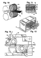
- Figures 9 to 13 illustrate another embodiment of the method and apparatus of the invention where similar elements are identified by the same reference numerals.
- a pair of wire separator rollers 54 are positioned before the coating booth 14 and a pair of wire merging rollers 56 are positioned after the coating booth 14.
- the separating rollers 54 separate the wires 12 to enable coating of the entire exterior surfaces of the wires 12.
- the separator rollers 54 are formed as two stepped, free rolling inter-digitated rollers which are driven by one or more drive motors (not illustrated) in the same direction as the direction of travel of the wires 12 and preferably are formed from metal.
- the rollers 54 assist in pulling the wires 12 from the rolls and advancing the wires 12 to the coating booth 14 and separate the wires 12 into pre-determined positions to expose all sides of the wires 12 to allow full encapsulation thereof during coating.
- each roller 54 includes a plurality of annular lands 58 and corresponding annular grooves 60 formed about their peripheries. To separate the wires 12, the rollers 54 are positioned in a staggered relationship with respect to each other and are inter-digitated so that lands 58 of each roller 54 seat within corresponding grooves 60 of the opposite roller.
- the lands 58 do not extend to the bottom of each groove 60 but provide a small pocket 62 within which each wire 12 is positioned. Due to the close tolerances between the wires 12 and pockets 62, the rollers 54 can exert a slight pull on the wires 12 without causing damage thereto.
- the separator rollers 54 separate the wires 12 in both a horizontal and a vertical direction with respect to Figure 11 regardless of how the wires 12 are fed into the separator rollers 54. This separating of the wires 12 provides a substantial amount of free space about the periphery of each wire 12 to enable coating about the entire periphery of each wire 12.
- the wires 12 In order to form the wires 12 into a strip or block, the wires 12 preferably are collated or merged back together after coating to form a band of wires 12 which is accomplished by the merging rollers 56.
- the merging rollers 56 preferably are substantially identical metal rollers having smooth surfaces where one is positioned above the wires 12 and one below the wires 12.
- the merging rollers 56 are driven in the same direction as the direction of travel of the wires 12 by one or more drive motors (not illustrated). Additionally, to provide tension and driving of the wires 12, the merging rollers 56 are positioned so that the vertical gap between the rollers 12 substantially corresponds to the thickness of the wires 12. The speed of the merging rollers 56 as well as the tension they provide readily can be adjusted.
- each merging roller 56 includes a scraper blade 64 and a vacuum head 66, similar to those of the wiping rollers 16.
- the blade 64 and vacuum head 66 are fixed with respect to the merging rollers 56.
- air jets can be utilised in place of the vacuum heads 66 to blow excess coating from the merging rollers 56 into a recovery container.
- Figures 14 and 15 depict the coating applied to wires 12 by another method of the present invention.
- Figure 14 specifically illustrates in substantially lighter colour two wires, one each positioned along the top and bottom horizontal edges with a dark horizontal strip there-between which is the coating joining the wires together.
- Figure 15 illustrates a single wire separated from a strip of wires with the coating thereon.
- the coating on the wires 12 is applied by precisely controlling the curing and cooling in the oven 18 and cooling chamber 20, respectively.
- Figure 14 illustrates, by quickly heating and quickly cooling the coated wires 12, voids, illustrated as random white shapes, are created in the dark horizontal coating layer.
- Such voids are randomly positioned and sized and are created by the water vapour by-products of the reaction which are "frozen" within the coating during rapid cooling. Failure to provide such rapid heating and cooling results in the coating continuing to flow filling up the voids and thus rendering a more solid coating.
- Such voids have become important in shearing of the wires or staples in a tool. Without the voids, the coating is very strong in shear which requires a tool that provides high shear force. With the voids, the shear strength is reduced to acceptable limits while increasing the pull out strength of the fasteners during use.
Landscapes
- Life Sciences & Earth Sciences (AREA)
- Engineering & Computer Science (AREA)
- Wood Science & Technology (AREA)
- Application Of Or Painting With Fluid Materials (AREA)
- Slide Fasteners, Snap Fasteners, And Hook Fasteners (AREA)
- Pharmaceuticals Containing Other Organic And Inorganic Compounds (AREA)
- Surface Treatment Of Glass Fibres Or Filaments (AREA)
- Slide Fasteners (AREA)
- Coating Apparatus (AREA)
Applications Claiming Priority (4)
| Application Number | Priority Date | Filing Date | Title |
|---|---|---|---|
| US12191593A | 1993-09-17 | 1993-09-17 | |
| US121915 | 1993-09-17 | ||
| US29700394A | 1994-08-31 | 1994-08-31 | |
| US297003 | 1994-08-31 |
Publications (3)
| Publication Number | Publication Date |
|---|---|
| EP0643998A2 true EP0643998A2 (de) | 1995-03-22 |
| EP0643998A3 EP0643998A3 (de) | 1995-11-08 |
| EP0643998B1 EP0643998B1 (de) | 1999-11-10 |
Family
ID=26819954
Family Applications (1)
| Application Number | Title | Priority Date | Filing Date |
|---|---|---|---|
| EP94306572A Expired - Lifetime EP0643998B1 (de) | 1993-09-17 | 1994-09-07 | Verfahren und Vorrichtung zum Beschichten |
Country Status (10)
| Country | Link |
|---|---|
| US (2) | US5882405A (de) |
| EP (1) | EP0643998B1 (de) |
| AT (1) | ATE186479T1 (de) |
| AU (1) | AU667784B2 (de) |
| BR (1) | BR9403097A (de) |
| CA (1) | CA2131467A1 (de) |
| DE (1) | DE69421585T2 (de) |
| ES (1) | ES2138049T3 (de) |
| MX (1) | MXPA94006859A (de) |
| NZ (1) | NZ264408A (de) |
Cited By (2)
| Publication number | Priority date | Publication date | Assignee | Title |
|---|---|---|---|---|
| DE19543665A1 (de) * | 1994-12-22 | 1996-06-27 | Leonische Drahtwerke Ag | Verfahren zum dichten, insbesondere elektrisch isolierenden Umhüllen von Gegenständen |
| EP1179372A3 (de) * | 2000-08-07 | 2003-01-02 | Illinois Tool Works Inc. | Pulverbeschichtetes Band und Methode zu seiner Herstellung |
Families Citing this family (44)
| Publication number | Priority date | Publication date | Assignee | Title |
|---|---|---|---|---|
| US7285131B1 (en) * | 1999-07-28 | 2007-10-23 | Cardica, Inc. | System for performing anastomosis |
| US7083858B1 (en) * | 2000-07-26 | 2006-08-01 | Worthen Industries, Inc. | Thermally activated adhesive films for the collation of wire staples |
| LU90623B1 (en) * | 2000-08-04 | 2002-02-05 | Trefilarbed Bissen Sa | Method and installation for coating wire material |
| US7011242B2 (en) * | 2001-12-07 | 2006-03-14 | Acme Staple Company, Inc. | Coated staple and fastening tool for the same |
| US7125577B2 (en) * | 2002-09-27 | 2006-10-24 | Surmodics, Inc | Method and apparatus for coating of substrates |
| USRE40722E1 (en) | 2002-09-27 | 2009-06-09 | Surmodics, Inc. | Method and apparatus for coating of substrates |
| US6931830B2 (en) * | 2002-12-23 | 2005-08-23 | Chase Liao | Method of forming a wire package |
| US6848607B2 (en) * | 2003-02-25 | 2005-02-01 | Acme Staple Company, Inc. | Fastening tool with modified driver travel path |
| EP1486262A1 (de) * | 2003-06-13 | 2004-12-15 | DMSYS sàrl | Vorrichtung und Verfahren zur Pulverbeschichtung |
| US7273337B2 (en) * | 2003-06-30 | 2007-09-25 | Illinois Tool Works Inc. | Partially coated fastener assembly and method for coating |
| US7958840B2 (en) * | 2004-10-27 | 2011-06-14 | Surmodics, Inc. | Method and apparatus for coating of substrates |
| US8070036B1 (en) | 2007-09-06 | 2011-12-06 | Cardica, Inc | True multi-fire surgical stapler configured to fire staples of different sizes |
| US7988026B2 (en) | 2007-09-06 | 2011-08-02 | Cardica, Inc. | Endocutter with staple feed |
| US9168039B1 (en) | 2007-09-06 | 2015-10-27 | Cardica, Inc. | Surgical stapler with staples of different sizes |
| US8403956B1 (en) | 2007-09-06 | 2013-03-26 | Cardica, Inc. | Multiple-use surgical stapler |
| US9364349B2 (en) | 2008-04-24 | 2016-06-14 | Surmodics, Inc. | Coating application system with shaped mandrel |
| US8397973B1 (en) | 2009-03-09 | 2013-03-19 | Cardica, Inc. | Wide handle for true multi-fire surgical stapler |
| US8317072B1 (en) | 2009-05-03 | 2012-11-27 | Cardica, Inc. | Feeder belt for true multi-fire surgical stapler |
| US8631992B1 (en) | 2009-05-03 | 2014-01-21 | Cardica, Inc. | Feeder belt with padded staples for true multi-fire surgical stapler |
| US8365975B1 (en) | 2009-05-05 | 2013-02-05 | Cardica, Inc. | Cam-controlled knife for surgical instrument |
| US8240538B1 (en) | 2009-05-29 | 2012-08-14 | Cardica, Inc. | True multi-fire surgical stapler with two-sided staple deployment |
| US8070034B1 (en) | 2009-05-29 | 2011-12-06 | Cardica, Inc. | Surgical stapler with angled staple bays |
| US8225980B1 (en) | 2009-06-02 | 2012-07-24 | Cardica, Inc. | True multi-fire surgical stapler with buttress strip |
| FR2953155B1 (fr) * | 2009-12-02 | 2011-12-30 | Peugeot Citroen Automobiles Sa | Procede de preparation de la caisse d'un vehicule automobile avant peinture |
| CN101829642B (zh) * | 2010-05-17 | 2011-11-02 | 上海华有光工贸有限公司 | 一种用于钢带保护的光固化涂料的连续涂布及固化装置 |
| US8662369B1 (en) | 2010-05-27 | 2014-03-04 | Cardica, Inc. | Barbed surgical staple |
| US8439246B1 (en) | 2010-07-20 | 2013-05-14 | Cardica, Inc. | Surgical stapler with cartridge-adjustable clamp gap |
| US8636189B1 (en) | 2011-04-19 | 2014-01-28 | Cardica, Inc. | Active wedge for surgical stapler |
| US9655615B2 (en) | 2011-04-19 | 2017-05-23 | Dextera Surgical Inc. | Active wedge and I-beam for surgical stapler |
| US8631990B1 (en) | 2011-04-25 | 2014-01-21 | Cardica, Inc. | Staple trap for surgical stapler |
| US9320519B1 (en) | 2011-04-26 | 2016-04-26 | Cardica, Inc. | Single-trigger clamping and firing of surgical stapler |
| US9155536B1 (en) | 2011-04-26 | 2015-10-13 | Cardica, Inc. | Circular stapler |
| US9084600B1 (en) | 2012-02-17 | 2015-07-21 | Cardica, Inc. | Anvil-side staple trap |
| MX351261B (es) | 2012-06-01 | 2017-10-06 | Surmodics Inc | Aparato y método para recubrir catéteres con globo. |
| US9827401B2 (en) | 2012-06-01 | 2017-11-28 | Surmodics, Inc. | Apparatus and methods for coating medical devices |
| US9408605B1 (en) | 2012-07-12 | 2016-08-09 | Cardica, Inc. | Single-trigger clamping and firing of surgical stapler |
| US11090468B2 (en) | 2012-10-25 | 2021-08-17 | Surmodics, Inc. | Apparatus and methods for coating medical devices |
| US9283350B2 (en) | 2012-12-07 | 2016-03-15 | Surmodics, Inc. | Coating apparatus and methods |
| WO2020112816A1 (en) | 2018-11-29 | 2020-06-04 | Surmodics, Inc. | Apparatus and methods for coating medical devices |
| CN109985759A (zh) * | 2019-04-19 | 2019-07-09 | 天津吉茂制钉有限公司 | 一种同步拼线机设备 |
| US11819590B2 (en) | 2019-05-13 | 2023-11-21 | Surmodics, Inc. | Apparatus and methods for coating medical devices |
| US11776714B2 (en) * | 2020-11-13 | 2023-10-03 | E-Wireligner Co., Ltd. | Device for coating a wire with polymer fibers and method thereof |
| US12496612B2 (en) | 2021-01-08 | 2025-12-16 | Surmodics, Inc. | Coating application system and methods for coating rotatable medical devices |
| WO2023083697A1 (en) * | 2021-11-10 | 2023-05-19 | Nv Bekaert Sa | Resin applicator for coating metal wire and associated method for coating. |
Family Cites Families (18)
| Publication number | Priority date | Publication date | Assignee | Title |
|---|---|---|---|---|
| US3234572A (en) * | 1962-11-13 | 1966-02-15 | Swingfast Inc | Method of and means for making nails, on the order of finishing nails, brads, and the like |
| US3390039A (en) * | 1964-10-09 | 1968-06-25 | Eastman Kodak Co | Method and apparatus for making additive filters |
| FR96143E (fr) * | 1967-11-30 | 1972-05-19 | Kalle Ag | Procédé pour la fabrication de produits poreux. |
| US3733592A (en) * | 1968-03-22 | 1973-05-15 | R Applequist | Split pawl positioning mechanism for a magnetic head |
| US3813985A (en) * | 1969-07-30 | 1974-06-04 | Spotnails | Fasteners and method of manufacture thereof |
| DE2040500C3 (de) * | 1970-08-14 | 1974-11-21 | Vereinigte Papierwerke Schickedanz & Co, 8500 Nuernberg | Verfahren und Vorrichtung zum Herstellen von verstärkten nichtgewebten Flächengebilden |
| GB1352391A (en) * | 1971-06-10 | 1974-05-08 | Ici Ltd | Production of fibre reinforced thermoplastic materials |
| GB1422396A (en) * | 1973-01-26 | 1976-01-28 | Ciba Geigy Ag | Film adhesives |
| US3877414A (en) * | 1973-06-04 | 1975-04-15 | Acrometal Products Inc | Apparatus for coating wire filament with liquid |
| CA1039126A (en) * | 1976-02-05 | 1978-09-26 | Canada Wire And Cable Limited | Electrostatic powder deposition on elongated substrates in plural fusible layers |
| US4275813A (en) * | 1979-06-04 | 1981-06-30 | United States Surgical Corporation | Coherent surgical staple array |
| DE2930870C2 (de) * | 1979-07-30 | 1981-04-02 | Felten & Guilleaume Carlswerk AG, 5000 Köln | Verfahren und Vorrichtung zum Herstellen von lackisolierten Wickeldrähten, insbesondere Starkdrähten |
| US4356212A (en) * | 1981-04-20 | 1982-10-26 | The Goodyear Tire & Rubber Company | Method and apparatus for treating textile cord |
| US4368214A (en) * | 1981-06-12 | 1983-01-11 | Electrostatic Equipment Corp. | Method and apparatus for producing electrical conductors |
| US4353325A (en) * | 1981-09-28 | 1982-10-12 | Loctite Corporation | Sealant applying apparatus |
| US5033181A (en) * | 1990-06-08 | 1991-07-23 | Illinois Tool Works Inc. | Method for manufacturing nails |
| US5208077A (en) * | 1990-11-09 | 1993-05-04 | Florida Wire And Cable Company | Method for a composite material comprising coated and filled metal strand for use in prestressed concrete, stay cables for cable-stayed bridges and other uses |
| US5441373A (en) * | 1993-09-07 | 1995-08-15 | Illinois Tool Works Inc. | Coated fastener |
-
1994
- 1994-09-06 CA CA002131467A patent/CA2131467A1/en not_active Abandoned
- 1994-09-06 NZ NZ264408A patent/NZ264408A/en not_active IP Right Cessation
- 1994-09-07 AT AT94306572T patent/ATE186479T1/de not_active IP Right Cessation
- 1994-09-07 DE DE69421585T patent/DE69421585T2/de not_active Expired - Lifetime
- 1994-09-07 ES ES94306572T patent/ES2138049T3/es not_active Expired - Lifetime
- 1994-09-07 EP EP94306572A patent/EP0643998B1/de not_active Expired - Lifetime
- 1994-09-07 MX MXPA94006859A patent/MXPA94006859A/es unknown
- 1994-09-07 AU AU71670/94A patent/AU667784B2/en not_active Ceased
- 1994-09-19 BR BR9403097A patent/BR9403097A/pt not_active Application Discontinuation
-
1996
- 1996-08-30 US US08/704,941 patent/US5882405A/en not_active Expired - Fee Related
- 1996-10-31 US US08/741,946 patent/US5875538A/en not_active Expired - Fee Related
Cited By (5)
| Publication number | Priority date | Publication date | Assignee | Title |
|---|---|---|---|---|
| DE19543665A1 (de) * | 1994-12-22 | 1996-06-27 | Leonische Drahtwerke Ag | Verfahren zum dichten, insbesondere elektrisch isolierenden Umhüllen von Gegenständen |
| EP1179372A3 (de) * | 2000-08-07 | 2003-01-02 | Illinois Tool Works Inc. | Pulverbeschichtetes Band und Methode zu seiner Herstellung |
| US6565926B2 (en) | 2000-08-07 | 2003-05-20 | Illinois Tool Works | Powder coated strap and method for making same |
| US6846362B2 (en) | 2000-08-07 | 2005-01-25 | Illinois Tool Works, Inc. | Powder coated strap and method for making same |
| US7097897B1 (en) | 2000-08-07 | 2006-08-29 | Illinois Tool Works Inc. | Powder coated strap and method for making same |
Also Published As
| Publication number | Publication date |
|---|---|
| DE69421585T2 (de) | 2000-05-04 |
| ES2138049T3 (es) | 2000-01-01 |
| BR9403097A (pt) | 1996-09-03 |
| EP0643998B1 (de) | 1999-11-10 |
| EP0643998A3 (de) | 1995-11-08 |
| NZ264408A (en) | 1996-06-25 |
| CA2131467A1 (en) | 1995-03-18 |
| DE69421585D1 (de) | 1999-12-16 |
| AU7167094A (en) | 1995-04-13 |
| MXPA94006859A (es) | 2004-08-20 |
| ATE186479T1 (de) | 1999-11-15 |
| AU667784B2 (en) | 1996-04-04 |
| US5882405A (en) | 1999-03-16 |
| US5875538A (en) | 1999-03-02 |
Similar Documents
| Publication | Publication Date | Title |
|---|---|---|
| EP0643998B1 (de) | Verfahren und Vorrichtung zum Beschichten | |
| AU2004202631B2 (en) | Partially coated fastener assembly and method for coating | |
| EP2785596B1 (de) | Vorrichtung zur bildung von verpackungseinheiten | |
| DE4001624B4 (de) | Haltevorrichtung für Leisten sowie Vorrichtung zur Abgabe einer Leiste einer vorgegebenen Länge | |
| EP2785597B1 (de) | Vorrichtung zur bildung von mehrreihigen verpackungseinheiten | |
| US4665679A (en) | Apparatus for binding elongate products | |
| DE4309043A1 (de) | Verfahren und Vorrichtung zum Verteilen von Gegenständen, insbesondere flächenartig ausgebildeten | |
| EP2371527B1 (de) | Verfahren und Vorrichtung zum Herstellen von (Tabak-)Beuteln | |
| NZ223229A (en) | Pipe bundling apparatus: screw mechanism conveys pipes to bundler | |
| EP2373432A1 (de) | Verfahren zur herstellung von lackierten schrauben oder n?geln in einem magazinstreifen | |
| US11305511B2 (en) | Engineered floor board | |
| DE19631834C2 (de) | Vorrichtung zum Aufbringen von Etiketten auf flache Sendungen | |
| DE60121492T2 (de) | Verfahren und Vorrichtung zum Anbringen von Siegelmarken an Zigarettenpackungen | |
| US5849138A (en) | Labeling system | |
| DE19736388A1 (de) | Verfahren und Vorrichtung zum Transportieren von Banderolen oder dergleichen | |
| DE102013114648A1 (de) | Verfahren und Vorrichtung zum Anbringen von Tragegriffen an Packmitteln oder Packmittelgruppen sowie Packmittel oder Packmittelgruppen | |
| JP3039732B2 (ja) | カートンの移送構造 | |
| DE102024122385A1 (de) | Etikettiervorrichtung zum Etikettieren von Mantelflächen von Objekten, insbesondere von zylindrischen Objekten | |
| DE19802062C1 (de) | Verfahren und Vorrichtung zum Fördern von Produkten | |
| US7121952B2 (en) | Method and apparatus for laser welding of flat stamped fasteners and resulting clip | |
| EP0910537A1 (de) | Vorrichtung zum aufbringen von etiketten | |
| DE2307238C3 (de) | Beschichtungsvorrichtung zum Auftragen eines Überzugs an den Schäften von mit Köpfen versehenen Gegenständen, insbesondere Schrauben | |
| US6729962B1 (en) | Method and apparatus for laser welding of flat stamped fasteners into clips, and resulting clip | |
| JPH06135413A (ja) | 金属板コイルの紙敷き装置 | |
| JPH0253537A (ja) | 高能率磨棒鋼自動製造装置 |
Legal Events
| Date | Code | Title | Description |
|---|---|---|---|
| PUAI | Public reference made under article 153(3) epc to a published international application that has entered the european phase |
Free format text: ORIGINAL CODE: 0009012 |
|
| AK | Designated contracting states |
Kind code of ref document: A2 Designated state(s): AT DE ES FR GB IT |
|
| PUAL | Search report despatched |
Free format text: ORIGINAL CODE: 0009013 |
|
| AK | Designated contracting states |
Kind code of ref document: A3 Designated state(s): AT DE ES FR GB IT |
|
| 17P | Request for examination filed |
Effective date: 19960503 |
|
| 17Q | First examination report despatched |
Effective date: 19980421 |
|
| GRAG | Despatch of communication of intention to grant |
Free format text: ORIGINAL CODE: EPIDOS AGRA |
|
| GRAG | Despatch of communication of intention to grant |
Free format text: ORIGINAL CODE: EPIDOS AGRA |
|
| GRAH | Despatch of communication of intention to grant a patent |
Free format text: ORIGINAL CODE: EPIDOS IGRA |
|
| GRAH | Despatch of communication of intention to grant a patent |
Free format text: ORIGINAL CODE: EPIDOS IGRA |
|
| GRAA | (expected) grant |
Free format text: ORIGINAL CODE: 0009210 |
|
| AK | Designated contracting states |
Kind code of ref document: B1 Designated state(s): AT DE ES FR GB IT |
|
| REF | Corresponds to: |
Ref document number: 186479 Country of ref document: AT Date of ref document: 19991115 Kind code of ref document: T |
|
| REF | Corresponds to: |
Ref document number: 69421585 Country of ref document: DE Date of ref document: 19991216 |
|
| REG | Reference to a national code |
Ref country code: ES Ref legal event code: FG2A Ref document number: 2138049 Country of ref document: ES Kind code of ref document: T3 |
|
| ITF | It: translation for a ep patent filed | ||
| ET | Fr: translation filed | ||
| PLBE | No opposition filed within time limit |
Free format text: ORIGINAL CODE: 0009261 |
|
| STAA | Information on the status of an ep patent application or granted ep patent |
Free format text: STATUS: NO OPPOSITION FILED WITHIN TIME LIMIT |
|
| 26N | No opposition filed | ||
| REG | Reference to a national code |
Ref country code: GB Ref legal event code: IF02 |
|
| PGFP | Annual fee paid to national office [announced via postgrant information from national office to epo] |
Ref country code: AT Payment date: 20040819 Year of fee payment: 11 |
|
| PGFP | Annual fee paid to national office [announced via postgrant information from national office to epo] |
Ref country code: ES Payment date: 20041008 Year of fee payment: 11 |
|
| PG25 | Lapsed in a contracting state [announced via postgrant information from national office to epo] |
Ref country code: IT Free format text: LAPSE BECAUSE OF NON-PAYMENT OF DUE FEES;WARNING: LAPSES OF ITALIAN PATENTS WITH EFFECTIVE DATE BEFORE 2007 MAY HAVE OCCURRED AT ANY TIME BEFORE 2007. THE CORRECT EFFECTIVE DATE MAY BE DIFFERENT FROM THE ONE RECORDED. Effective date: 20050907 Ref country code: AT Free format text: LAPSE BECAUSE OF NON-PAYMENT OF DUE FEES Effective date: 20050907 |
|
| PG25 | Lapsed in a contracting state [announced via postgrant information from national office to epo] |
Ref country code: ES Free format text: LAPSE BECAUSE OF NON-PAYMENT OF DUE FEES Effective date: 20050908 |
|
| REG | Reference to a national code |
Ref country code: ES Ref legal event code: FD2A Effective date: 20050908 |
|
| PGFP | Annual fee paid to national office [announced via postgrant information from national office to epo] |
Ref country code: DE Payment date: 20130927 Year of fee payment: 20 |
|
| PGFP | Annual fee paid to national office [announced via postgrant information from national office to epo] |
Ref country code: FR Payment date: 20130919 Year of fee payment: 20 Ref country code: GB Payment date: 20130927 Year of fee payment: 20 |
|
| REG | Reference to a national code |
Ref country code: DE Ref legal event code: R071 Ref document number: 69421585 Country of ref document: DE |
|
| REG | Reference to a national code |
Ref country code: GB Ref legal event code: PE20 Expiry date: 20140906 |
|
| PG25 | Lapsed in a contracting state [announced via postgrant information from national office to epo] |
Ref country code: DE Free format text: LAPSE BECAUSE OF EXPIRATION OF PROTECTION Effective date: 20140909 |
|
| PG25 | Lapsed in a contracting state [announced via postgrant information from national office to epo] |
Ref country code: GB Free format text: LAPSE BECAUSE OF EXPIRATION OF PROTECTION Effective date: 20140906 |