EP0644040A1 - Procédé et machine pour l'application de matières composites - Google Patents
Procédé et machine pour l'application de matières composites Download PDFInfo
- Publication number
- EP0644040A1 EP0644040A1 EP94107979A EP94107979A EP0644040A1 EP 0644040 A1 EP0644040 A1 EP 0644040A1 EP 94107979 A EP94107979 A EP 94107979A EP 94107979 A EP94107979 A EP 94107979A EP 0644040 A1 EP0644040 A1 EP 0644040A1
- Authority
- EP
- European Patent Office
- Prior art keywords
- tape
- compaction
- compacting
- pressure
- composite material
- Prior art date
- Legal status (The legal status is an assumption and is not a legal conclusion. Google has not performed a legal analysis and makes no representation as to the accuracy of the status listed.)
- Withdrawn
Links
Images


Classifications
-
- B—PERFORMING OPERATIONS; TRANSPORTING
- B29—WORKING OF PLASTICS; WORKING OF SUBSTANCES IN A PLASTIC STATE IN GENERAL
- B29C—SHAPING OR JOINING OF PLASTICS; SHAPING OF MATERIAL IN A PLASTIC STATE, NOT OTHERWISE PROVIDED FOR; AFTER-TREATMENT OF THE SHAPED PRODUCTS, e.g. REPAIRING
- B29C70/00—Shaping composites, i.e. plastics material comprising reinforcements, fillers or preformed parts, e.g. inserts
- B29C70/04—Shaping composites, i.e. plastics material comprising reinforcements, fillers or preformed parts, e.g. inserts comprising reinforcements only, e.g. self-reinforcing plastics
- B29C70/28—Shaping operations therefor
- B29C70/30—Shaping by lay-up, i.e. applying fibres, tape or broadsheet on a mould, former or core; Shaping by spray-up, i.e. spraying of fibres on a mould, former or core
- B29C70/38—Automated lay-up, e.g. using robots, laying filaments according to predetermined patterns
- B29C70/386—Automated tape laying [ATL]
- B29C70/388—Tape placement heads, e.g. component parts, details or accessories
-
- Y—GENERAL TAGGING OF NEW TECHNOLOGICAL DEVELOPMENTS; GENERAL TAGGING OF CROSS-SECTIONAL TECHNOLOGIES SPANNING OVER SEVERAL SECTIONS OF THE IPC; TECHNICAL SUBJECTS COVERED BY FORMER USPC CROSS-REFERENCE ART COLLECTIONS [XRACs] AND DIGESTS
- Y10—TECHNICAL SUBJECTS COVERED BY FORMER USPC
- Y10T—TECHNICAL SUBJECTS COVERED BY FORMER US CLASSIFICATION
- Y10T156/00—Adhesive bonding and miscellaneous chemical manufacture
- Y10T156/10—Methods of surface bonding and/or assembly therefor
-
- Y—GENERAL TAGGING OF NEW TECHNOLOGICAL DEVELOPMENTS; GENERAL TAGGING OF CROSS-SECTIONAL TECHNOLOGIES SPANNING OVER SEVERAL SECTIONS OF THE IPC; TECHNICAL SUBJECTS COVERED BY FORMER USPC CROSS-REFERENCE ART COLLECTIONS [XRACs] AND DIGESTS
- Y10—TECHNICAL SUBJECTS COVERED BY FORMER USPC
- Y10T—TECHNICAL SUBJECTS COVERED BY FORMER US CLASSIFICATION
- Y10T156/00—Adhesive bonding and miscellaneous chemical manufacture
- Y10T156/12—Surface bonding means and/or assembly means with cutting, punching, piercing, severing or tearing
- Y10T156/1348—Work traversing type
-
- Y—GENERAL TAGGING OF NEW TECHNOLOGICAL DEVELOPMENTS; GENERAL TAGGING OF CROSS-SECTIONAL TECHNOLOGIES SPANNING OVER SEVERAL SECTIONS OF THE IPC; TECHNICAL SUBJECTS COVERED BY FORMER USPC CROSS-REFERENCE ART COLLECTIONS [XRACs] AND DIGESTS
- Y10—TECHNICAL SUBJECTS COVERED BY FORMER USPC
- Y10T—TECHNICAL SUBJECTS COVERED BY FORMER US CLASSIFICATION
- Y10T156/00—Adhesive bonding and miscellaneous chemical manufacture
- Y10T156/17—Surface bonding means and/or assemblymeans with work feeding or handling means
- Y10T156/1788—Work traversing type and/or means applying work to wall or static structure
Definitions
- his invention relates to machines which lay strips of composite material onto a surface, and particularly but not exclusively, where it is desirable to compact strips having tails, i.e., trailing sections of material which are less than full strip width.
- this invention relates to compaction of composite tape by a compactor having at least two levels of compaction force.
- Prior Art Figure 1 depicts a high rail gantry tape laying machine 10 wherein a tape laying head 11 is transported coordinately on horizontal side rails 12 and transverse gantry rails 13 under a program commanded by a numerical control (NC) unit 14.
- NC numerical control
- a contoured tape laydown surface 15, or tool, is positionable with respect to the tape laying head 11 to form laminated composite structures.
- the tape laying head 11 comprises, in part, a main frame 16 supporting a tape supply reel 17.
- the supply reel 17 carries a tape structure 18 comprising a filamentous composite tape and a paper backing.
- the tape structure 18 is trained under a tape compactor unit 19 and backing is accumulated on a take-up reel 20, in a manner well-known in the art.
- the tape laying head 11 is movable along a vertical, or Z-axis 21 to adapt to changing tool heights along the tape path, and the entire tape head 11 is rotatable around the vertical axis 21.
- Figure 2a depicts a schematic of the tape laying head 11 movable in a direction "X" with respect to a tool 22.
- the tape laying head 11 has a supply reel 17 which feeds out a tape structure 18 comprising a composite tape 23 releasably attached to a backing 24 such as a paper strip.
- the tape structure 18 feeds through a cutter unit 25 and tape guide chute 26 to its lowermost position, adjacent the tool 22, where it then passes under a presser shoe or primary compactor 27 of the tape compactor unit 19.
- the backing 24 is separated and pulled onto the take-up reel 20 on the head 11.
- the prior art tape head 11 includes a tail compactor 31, which is a roller 32, carried on a pivotable bell crank 23.
- the bell crank 23 is swung from a pivot joint 34 on the head 11 by a cylinder 35, reacting against the head 11, to drive the tail compactor 31 against the tape 23 in the manner shown in Figure 2c.
- the tail compactor 31 is located at a spot between the backing 24 and the previously laid tape 23a, so that it contacts only tape 23 when swung into the "down" position.
- linkage 36 attached from the bell crank 33 to the primary compactor 27 and to a backing guide 37, the downward stroke of the tail compactor 31 with respect to the tape laying head 11 forces the primary compactor 27 and entire tape head 11 up, away from the laydown surface 28, and the linkage 36 also moves the backing guide 37 into a position to help steer the backing 24 on its way to the take-up reel 20.
- the primary compactor Since the primary compactor is affixed to the tape head, the primary compaction force is provided by the head itself. And, since the tail compactor is thrust into position by reaction against the tape laying head, the tail compaction force is likewise provided by the head itself. Additionally, the primary and tail compactors, as depicted, are spaced from one another along a horizontal plane, and this may prohibit application of the head to certain contoured parts which deviate substantially from a flat surface, along the tape length.
- US-A-4954204 teaches a presser member for contoured surfaces, and the entire disclosure and teaching of the '204 patent is expressly incorporated herein by reference.
- the '204 device is depicted herein as Prior Art Figures 3, 4, 5a, 5b, and 5c.
- Prior Art Figure 3 the '204 patent teaches a presser member 38 which is affixed to the bottom of a tape laying head 11, as a primary compactor, but wherein the primary compaction force is obtained from an actuator 39 within the device itself; thus the presser member elements move with respect to the tape head 11.
- the presser member elements comprise a shoe plate stack 40, i.e., plurality of adjacent shoe plates 41 of common cross-section (see Figure 4), which may adapt to contours occurring across the tape strip 23.
- the presser member 38 is a four-bar linkage of the double-slider type, where a horizontal slider 42 is connected by a control link 43 to a vertical slider (the shoe plate stack 40).
- the presser member 38 has a housing 44, quarter-rounded at its lower rear surface and hollowed out to accommodate detail pieces.
- the top of the housing supports a centrally located air cylinder 45, having a piston rod 46 extending frontwardly, i.e., to the right of the figure.
- a pair of parallel guide rods 47a,b Immediately adjacent the front of the cylinder 45 is a pair of parallel guide rods 47a,b, one at each side of the assembly.
- the horizontal slider 42 rides on the guide rods 47a,b, and the end of the piston rod 46 is affixed to the slider 42.
- Figure 4 shows the shoe plates 41 in relation to the control link 43 and a control rod 48 which extends through the shoe plates 41.
- the actuator 39 for biasing the plates 41 downwardly, away from the housing 44.
- the actuator 39 is a closed bladder spring, where a chamber 49 is faced with a flexible membrane 50 which contacts the top edges of the shoe plates 41. Pressurized fluid is ducted into the chamber through a port 51 to load the compliant membrane 50 against the shoe plates 41.
- Figure 5a is a diagrammatic view of the elements of Figure 3, showing the quarter-round housing 44 supporting the vertically movable shoe plate stack 40, with a latch finger 52 "up” and the slider 42 moved to the right against the latch finger 52.
- the control link 43 is shown connected to the control rod 48 which evens out, or "nulls" all plates at a known dimension, Z'.
- the downward biasing force provided by the membrane 50 is depicted as a bladder spring 53 reacting against the top edge 51 of the shoe plates 41.
- the position of the elements in Figure 5a is used for programming all vertical, or Z-axis dimensions, providing a known point from which the shoe plates 41 may float up and down.
- Figure 5b depicts elements of Figure 5a in an alternate position, where the latch finger 52 is "down” and the slider 42 is moved leftwardly to the fully-retracted position.
- This position of the presser member 38 is used for compacting a tape strip 23 against the tool laydown surface 28.
- the control link 43 has moved the horizontal control rod 48 to an intermediate position within the shoe plate slot 54; the shoe plates 41 are free to float on tool contours as the bladder spring 53 biases the entire shoe plate stack 40 against the tape 23.
- Figure 5c depicts the latch finger 52 retracted, and the slider 42 now fired to the fully-advanced position, all the way to the right.
- control link 43 now pulls the control rod 48 to a new raised position, thus fully-retracting the vertically-movable shoe plates 41 upwardly into the housing 44, compressing the biasing bladder spring 53.
- This position permits the use of auxiliary equipment, such as a tail compacting roller 55.
- the present invention provides a compactor assembly for composite material, and method of use, wherein a primary compactor is independently powered with respect to a machine head and combined with a secondary compactor which is likewise independently powered with respect to the head, and where at least one of the compactors may be operated with at least two different levels of compaction force.
- the present invention also provides a composite tape strip compactor assembly, and method of use, in which a main compactor is adaptable to contour changes occurring across the tape strip and a tail compactor is capable of tail compaction on surfaces deviating substantially from a flat plane along the tape length, and where at least one of the compactors may be operated with at least two different levels of compaction force.
- the present invention further provides a compactor assembly for composite tape, and method of use, in which a main compactor is utilized for laying essentially a full-width tape strip at a tape laydown point defined with respect to a tape laying head, and in which the main compactor is displaced by a tail compactor which may finish laying the tail of the tape strip at the tape laydown point, and where at least one of the compactors may be operated with at least two different levels of compaction force.
- the present invention further provides a compactor assembly for composite tape, and method of use, wherein main compaction and tail compaction occur at substantially the same point with respect to the tape laying head which carries the compactor assembly, and where at least one of the compactors may be operated with at least two different levels of compaction force.
- the present invention further provides a compactor assembly for composite tape, and method of use, wherein primary tape strip compaction and tail compaction are independent of tape laying head movement and are provided by the same actuator, carried by the tape laying head, and where at least one of the compactors may be operated with at least two different levels of compaction force.
- the present invention further provides a compactor assembly for composite tape, and method of use, in which linkage is utilized for simultaneously switching positions of the main compactor and tail compactor with respect to a tape laydown point, and where at least one of the compactors may be operated with at least two different levels of compaction force.
- the present invention further provides a method for compacting composite materials, comprising the steps: placing composite material on a support surface; positioning a compaction frame proximal said support surface; providing a compaction element on said frame between said frame and said material; providing a fluid actuator between said element and said frame; porting pressurized fluid into said actuator; applying a first compaction force to said material with said compaction element; varying the pressure of said pressurized fluid; and applying a second compaction force to said material with said compaction element.
- a tape head 60 is shown with an improved tape compactor assembly 61 affixed to its bottom surface.
- the tape head 60 is of a type which may be used with the tape laying machine 10 of Figure 1.
- the tape compactor assembly 61 will move in a forward direction "X" with the tape head 60, to the right of the figure, when laying tape 23, and the head 60 thus has a front end 60a, at the right of the figure, and a rear end 60b to the left of the figure
- the assembly 61 includes a housing 62 which is quarter-rounded at its lower rear surface and hollowed out to accommodate detail pieces (not shown).
- the top surface of the housing 62 has a frame 63 affixed thereto, which extends frontwardly.
- the frame 63 serves as a mounting for an air cylinder 64, which has a piston rod 65 extending frontwardly.
- the frame 63 also supports a pair of parallel guide rods 66a,b, one at each side of the assembly 61, and a horizontal slider 67 rides on the guide rods 66a,b and extends across the housing 62 from side-to-side (see also Figures 7 and 8).
- the slider 67 is affixed to the piston rod 65.
- the horizontal slider 67 has three specific positions:
- the latch finger 68 is powered in vertical directions by a compact fluid cylinder unit 69 secured to the bottom of the frame 63.
- Each side of the housing 62a,b has a vertical slider 70, constrained to move within a vertical track 71 along a vertical centerline 72 defined on the housing 62.
- a main compactor 73 Within the housing 62, immediately behind the vertical slider 70, is a main compactor 73.
- the main compactor 73 comprises a shoe plate stack 74 for contacting the backing 24 of a tape structure 18.
- the shoe plate stack 74 is a plurality of parallel, wafer-like shoe plates 75 guided for vertical movement with respect to one another within the housing 62.
- a vertical elongate slot 76 of common size is provided in line through all of the plates 75, and a control rod 77 extends horizontally, from side to side through all of the slots 76 and is affixed to the vertical sliders 70.
- the control rod 77 is positioned approximately mid-way along the vertical slot 76 so it will not interfere with compactor movement which may require the shoe plates 75 to adapt to a variety of contours across the tape width. This is the normal tape laying position.
- a bladder spring 79 has been devised, in the manner of U.S. Patent 4,954,204, wherein the housing 62 has a closed chamber 80 formed immediately above the shoe plate stack 74.
- the chamber 80 includes a flexible membrane 81 extending across the shoe plates 75, in contact with and spanning the top edges 75b.
- the chamber 80 is provided with an orifice 82 so that air or other fluid medium may be introduced into the chamber 80 and, thus, pressurize the membrane 81 to provide a downward biasing force to the entire stack of plates 75.
- the membrane 81 is yieldable, to accommodate surface contour variances which will cause the plates 75 to shift vertically, relative to one another, as the tape 23 is laid.
- the air valve unit 82a ( Figures 9, 15, 16) employed to pressurize the bladder spring 79 produces a pressure output which varies in proportion to the magnitude of an electrical signal.
- a valve unit is the Pneutronics VIP-FLEX Pressure Control unit, available from LDI Pneutronics Corp., Hollis, NH 03049. Therefore, this valve unit 82 may be controlled in accordance with an NC program to vary air pressure and consequent force directed against the tape 23.
- compaction of full-width tape may be performed at a constant pressure.
- unit loading on a tapered tail may be kept constant by changing the total downward force acting on the tail compaction roller; i.e., by varying air pressure in accordance with the tail profile.
- a flexible sheet or skid 84 is attached to the front of the housing 62, and directed around the nose, or bottom edge 75a of the shoe plates 75 to present a smooth surface against the backing 24. It may be appreciated, however, that some embodiments may omit the skid 84.
- the skid 84 is guided around the quarter-round section, within a surface channel or relief 85, and is held taut by a strap 86.
- the strap 86 is affixed to the skid 84 and tensioned by a coiling device 87 carried on the tape laying head 60.
- the tape structure 18 is shown coming from the tape guide chute 26 to the tape lay-down point 88 established by the intersection of the vertical centerline 72 and a horizontal plane 89 defined on the work surface 78.
- tape 23 is deposited on the work surface 78, and the backing 24 is separated from the tape 23 and pulled upwardly against the skid 84, while running to a take-up reel (not shown).
- the roller 90 depicted in Figure 6 is a tail compactor, and is located between the tape 23 and the backing 24, trailing the tape laydown point 88, in the manner taught in U.S. Patent 4,557,783, Prior Art Figure 2a.
- the roller 90 is shown in its home position, swung all the way to the left.
- a tail compactor is a secondary compactor used for compacting tape of less than full width.
- the roller 90 is carried at one end of a first elongate link 91, which is pivotally connected at its other end to the vertical slider 70 about a first horizontal pivot axis 92.
- the horizontal slider 67 has a depending section 67a at each side of the housing 62 (see Figure 7) which extends approximately midway down the housing 62, and a second elongate link 93 is pivotally connected at one end to the horizontal slider 67 about a second horizontal pivot axis 94 while its other link end is pivotally connected to the first link 91 about a third horizontal pivot axis 95 lying approximately midway between the ends of the first link 91.
- the first link 91 also includes a cam follower 96 which extends horizontally from the link 91 into a cam slot 97 provided on the housing 62 (see also Figure 10).
- the cam slot 97 governs the first link 91 and, consequently, movement of the tail compaction roller 90 as the horizontal slider 67 is driven by the cylinder 64.
- the cam slot 97 is arcuate and upwardly arched, from its initial portion, thereafter sloping downwardly towards the vertical slider 70. And, while the cam follower 96 is accurately guided within the cam slot 97 for most of the path, the end of the slot 97 is relieved, as will be described later in connection with Figure 11c.
- first and second links 91,93 under discussion are shown on one side 62a of the housing 62, i.e., facing the viewer, it will be appreciated that there are identical links 91,93 on the opposite side 62b of the assembly 61, and the tail compaction roller 90 spans the first links 91, as shown in Figure 8.
- Figure 11a depicts the elements of Figure 6, where the latch finger 68 is "down" and the slider 67 is moved leftwardly to the fully-retracted position.
- the main compactor 73 or shoe plate stack 74 is biased against a tape backing 24 which is being stripped from tape 23 laid to the laydown surface 78, and the position of the vertical slider 70 and its control rod 77 is such that the rod 77 will not hinder vertical float of the plates 75 (see also Figure 9).
- the bladder spring 79 biases the entire shoe plate stack 74 against the backing 24 and tape 23, and the shoe plates 75 can float in compliance with contour variances occurring across the tape width.
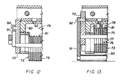
- Figure 11b depicts the housing 62 with the latch finger 68 "up” and the horizontal slider 67 moved to the right, against the latch finger 68. In this position, the vertical slider 70 is driven upward slightly so that its control rod 77 evens out, or "nulls" all plates 75 at a known dimension, Z' (see also Figure 12). The position of the elements in Figure 11b is utilized for programming all vertical, or Z-axis dimensions.
- Figure 11c depicts the latch finger 68 "down", and the horizontal slider 67 now fired to the fully-advanced position, all the way to the right.
- the vertical slider 70 is now driven to a new raised position where its control rod 77 drives the vertically-movable shoe plate stack 74 to a fully-retracted upward position into the housing 62, compressing the bladder spring 79 (see also Figure 13).
- the skid 84 will follow along with the stack 74.
- the first elongate link 91 is swung to a nearly vertical position, governed through most of its movement by the cam follower 96 travelling in the cam slot 97, so that the tail compaction roller 90 will be switched into the region of the tape laydown point 88, previously occupied by the now-retracted main compactor 73 (shoe plate stack 74).
- the linkage coupled with guidance provided by the cam follower 96, insures that the tail compaction roller 90 will move along a path which will not interfere with the substantial slope (approximately 15°) of the work surface 78 with respect to the horizontal plane 89.
- the tail compaction force is accomplished by the same bladder spring 79 which provides the main compactor force.
- the compressed bladder spring 79 attempts to drive the control rod downward along with the vertical slide 70, and the vertical slide 70 in turn, drives the first elongate link 91 and roller 90 downward against the tape tail 23a.
- the sides 97a,b of the cam slot 97 are slightly flared for clearance (see also Figure 14) when the cam follower 96 is positioned as in Figure 11c, so the first link 91 and roller 90 may move vertically against the tail 23a.
- the horizontal slider 67 is retracted to the left, causing the tail compaction roller 90 to swing back out to its home position, and permitting the main compactor 73 (shoe plate stack 74) to descend.
- Figures 6-9 depict an ideal situation for the invention, where it is assumed that the vertical slide 70 will move upward easily when the horizontal slide 67 is actuated. It is further assumed that the cam follower 96 moves without shake in the cam slot 97. In actual practice, though, frictional forces are present, and the cam slot 97 at each side 62a,b, of the housing 62 is manufactured with clearance; therefore, to ensure quick action and smoothness, a practical embodiment of the invention is further developed in Figure 14, where the following features may be seen:
- the vertical slide 70 may be provided with antifriction elements in certain applications. Similarly, provision of antifriction elements within the various slides, pivot joints and rollers herein, are deemed to be well within the ken of the machine designer.
- the actuator for the main compactor 73 comprises a bladder spring 79, having a closed chamber with a membrane covering
- the membrane 81 may be omitted, and fluid pressure may be applied directly against the top of the shoe plate stack 74 to bias the stack 74 in a downward direction.
- a resiliently faced element may be substituted for the main compactor 73, and other devices may be substituted for the tail compaction roller 90.
- FIG. 15 shows certain elements of Figure 9, wherein the main compactor 73, or shoe plate stack 74 is shown distributed across a tape strip 200 laid in a valley 201 of a work surface 202.
- the valve unit 82a is modified by command from the NC unit 14 to port a higher pressure P1 into the bladder spring 79 than is required for normal flat laying runs.
- the air valve unit 82a receives a supply of air or other fluid from a supply line 203, and is easily modulated or changed in response to an NC program, since the machine programmer will be well aware of the tool contours and tape strip placement requirements.
- Figure 16 depicts the elements of Figure 15 when changing to a profile which has a peak 204 occurring across the tape width.
- a lesser compaction force is needed than is required to lay the tape strip 200 into a valley 201 per Figure 15, and consequently, the valve unit 82a is managed by further instruction from the NC unit 14 to reduce the pressure from that of Figure 15 to a reduced pressure, P2.
- Figure 17 discloses a sequence drawing, in perspective, of application of a variable force tail compactor 205 to a linearly tapering tail 206 of a composite tape strip 207.
- a variable force tail compactor 205 to a linearly tapering tail 206 of a composite tape strip 207.
- five positions are shown along the tape tail 206 where it is desired to maintain a constant unit loading on the tail material with a tail compaction roller 90 which extends for the full width of the tape 207.
- the force applied to the roller 90 should decrease linearly from the beginning 208 of the tape tail 206 to the end 209.
- the five positions depicted illustrate force levels F1, F2, F3, F4 and F5, which correspond to pressure levels P1, P2, P3, P4 and P5.
- a pressure distribution graph 210 is shown in Figure 18, where the pressure varies linearly for the length of the tail, "L".
- the valve unit 82a is programmed for variable pressure along the tail 206.
- the tail compaction force is provided to the roller 90 by the bladder spring 79, pressurized by the valve unit 82a.
- FIG. 19 depicts a segmented compactor 211 from the '774 patent, which has a reference roller 212 at its centre position flanked by adjacent sliding rollers 213 which may move relative to the fixed reference roller 212.
- the actuator 214 for pressurizing the movable rollers 213 is also supplied with air from the valve unit 82a, and regulated by a numerical control program within the NC unit 14.
Landscapes
- Engineering & Computer Science (AREA)
- Robotics (AREA)
- Chemical & Material Sciences (AREA)
- Composite Materials (AREA)
- Mechanical Engineering (AREA)
- Moulding By Coating Moulds (AREA)
Applications Claiming Priority (2)
| Application Number | Priority Date | Filing Date | Title |
|---|---|---|---|
| US6801793A | 1993-05-27 | 1993-05-27 | |
| US68017 | 1993-05-27 |
Publications (1)
| Publication Number | Publication Date |
|---|---|
| EP0644040A1 true EP0644040A1 (fr) | 1995-03-22 |
Family
ID=22079900
Family Applications (1)
| Application Number | Title | Priority Date | Filing Date |
|---|---|---|---|
| EP94107979A Withdrawn EP0644040A1 (fr) | 1993-05-27 | 1994-05-24 | Procédé et machine pour l'application de matières composites |
Country Status (2)
| Country | Link |
|---|---|
| US (2) | US5738749A (fr) |
| EP (1) | EP0644040A1 (fr) |
Cited By (2)
| Publication number | Priority date | Publication date | Assignee | Title |
|---|---|---|---|---|
| US9656449B2 (en) | 2012-02-06 | 2017-05-23 | Rolls-Royce Plc | Consolidation device and method of using the same |
| US11040512B2 (en) | 2017-11-08 | 2021-06-22 | Northrop Grumman Systems Corporation | Composite structures, forming apparatuses and related systems and methods |
Families Citing this family (26)
| Publication number | Priority date | Publication date | Assignee | Title |
|---|---|---|---|---|
| EP0644040A1 (fr) * | 1993-05-27 | 1995-03-22 | Cincinnati Milacron Inc. | Procédé et machine pour l'application de matières composites |
| US6390169B1 (en) | 2000-02-23 | 2002-05-21 | The Boeing Company | Conformable compaction apparatus for use with a fiber placement machine |
| US7093641B2 (en) * | 2001-03-05 | 2006-08-22 | Henkel Corporation | Robotic tape applicator and method |
| US20050016671A1 (en) * | 2001-03-05 | 2005-01-27 | Sharp Terrance M. | Robotic tape applicator and method |
| US7249943B2 (en) * | 2003-08-01 | 2007-07-31 | Alliant Techsystems Inc. | Apparatus for forming composite stiffeners and reinforcing structures |
| US7836931B2 (en) * | 2004-06-22 | 2010-11-23 | Slyne William J | Tape laying apparatus and method |
| US7374625B2 (en) * | 2004-08-13 | 2008-05-20 | Henkel Corporation | Systems and methods for a robotic tape applicator |
| US7326312B1 (en) | 2004-09-09 | 2008-02-05 | Magus Intellectual Property Gmbh | Process for laying fiber tape |
| US7341086B2 (en) * | 2004-10-29 | 2008-03-11 | The Boeing Company | Automated fabric layup system and method |
| US7993480B2 (en) * | 2007-11-17 | 2011-08-09 | The Boeing Company | Method and apparatus for placing plies on curved substrates |
| US8220514B2 (en) * | 2005-06-10 | 2012-07-17 | North Cutting Systems, Llc | Tape laying apparatus and method |
| JP4953764B2 (ja) * | 2005-11-29 | 2012-06-13 | 株式会社東京精密 | 剥離テープ貼付方法および剥離テープ貼付装置 |
| US8042594B2 (en) * | 2006-06-28 | 2011-10-25 | Alliant Techsystems Inc. | Compaction device for fiber placement using interdependent segment travel |
| US7404868B2 (en) * | 2006-10-10 | 2008-07-29 | Accudyne Systems, Inc. | Tape placement head for applying thermoplastic tape to an object |
| US8052823B2 (en) | 2008-01-31 | 2011-11-08 | Alliant Techsystems Inc. | Stiffener tool positioning apparatus |
| DE102010010685A1 (de) | 2009-03-19 | 2011-02-03 | Airbus Operations Gmbh | Verfahren zur toleranzangepassten Klebstoffapplikation im Fahrzeugbau |
| DE102010010686A1 (de) * | 2009-03-19 | 2011-01-05 | Fraunhofer-Gesellschaft zur Förderung der angewandten Forschung e.V. | Verfahren und Vorrichtung zum klebtechnischen Fügen großflächiger Komponenten im Fahrzeugbau |
| US9662841B2 (en) | 2009-11-10 | 2017-05-30 | Orbital Atk, Inc. | Radially extending composite structures |
| US8282757B2 (en) * | 2009-11-10 | 2012-10-09 | Alliant Techsystems Inc. | Automated composite annular structure forming |
| US8721316B2 (en) * | 2012-01-26 | 2014-05-13 | Alliant Techsystems Inc. | Automated material delivery system |
| US9527237B2 (en) | 2013-01-04 | 2016-12-27 | Orbital Atk, Inc. | Induction heating compaction system |
| US9291060B2 (en) * | 2013-03-14 | 2016-03-22 | Rolls-Royce Corporation | High strength joints in ceramic matrix composite preforms |
| AT514550B1 (de) * | 2013-12-16 | 2015-02-15 | Gfm Gmbh | Vorrichtung zum Legen von Faserbändern |
| AT514797B1 (de) | 2013-12-16 | 2015-04-15 | Gfm Gmbh | Vorrichtung zum Legen von Faserbändern |
| US10829667B2 (en) * | 2015-07-24 | 2020-11-10 | The Boeing Company | Method and apparatus for applying a strip of material over an edge on a structure |
| JP7359654B2 (ja) * | 2019-11-07 | 2023-10-11 | 津田駒工業株式会社 | 自動積層装置 |
Citations (3)
| Publication number | Priority date | Publication date | Assignee | Title |
|---|---|---|---|---|
| EP0154321A1 (fr) * | 1984-03-05 | 1985-09-11 | Cincinnati Milacron Inc. | Appareil et machine pour étendre des cordes |
| EP0255425A1 (fr) * | 1986-07-21 | 1988-02-03 | Forest-Line | Dispositif pour la mise en forme automatique d'une nappe de fibres sur un moule, ainsi que machines comportant un tel dispositif |
| US5011563A (en) * | 1988-05-18 | 1991-04-30 | Shinnippon Koki Kabushiki Kaisha | Automatic tape affixing apparatus |
Family Cites Families (13)
| Publication number | Priority date | Publication date | Assignee | Title |
|---|---|---|---|---|
| US4351688A (en) * | 1979-12-10 | 1982-09-28 | General Dynamics Corporation | Composite tape laying machine |
| US4557783A (en) * | 1983-12-05 | 1985-12-10 | Cincinnati Milacron Inc. | Composite tape laying machine and method |
| US5022952A (en) * | 1985-12-13 | 1991-06-11 | Cincinnati Milacron Inc. | Fiber placement machine |
| US4750965A (en) * | 1986-03-28 | 1988-06-14 | The Ingersoll Milling Machine Company | Adaptive control for tape laying head having natural path generation |
| US4915771A (en) * | 1987-10-08 | 1990-04-10 | The Boeing Company | Segmented tape shoe |
| US4869774A (en) * | 1988-09-26 | 1989-09-26 | Cincinnati Milacron Inc. | Compliant presser member for fiber placement machine |
| US4954204A (en) * | 1988-11-25 | 1990-09-04 | Cincinnati Milacron Inc. | Presser member for contoured surfaces |
| DE4130269C2 (de) * | 1990-09-13 | 1996-05-23 | Toshiba Machine Co Ltd | Verfahren und Vorrichtung zum Herstellen laminierter Prepreg-Teile |
| US5269869A (en) * | 1993-02-12 | 1993-12-14 | Cincinnati Milacron Inc. | Tape laying apparatus |
| US5352306A (en) * | 1993-05-27 | 1994-10-04 | Cincinnati Milacron Inc. | Tape laying apparatus and method |
| US5316612A (en) * | 1993-05-27 | 1994-05-31 | Cincinnati Milacron Inc. | Tape compactor |
| EP0644040A1 (fr) * | 1993-05-27 | 1995-03-22 | Cincinnati Milacron Inc. | Procédé et machine pour l'application de matières composites |
| US5454897A (en) * | 1994-05-02 | 1995-10-03 | Cincinnati Milacron Inc. | Presser member for fiber laying machine |
-
1994
- 1994-05-24 EP EP94107979A patent/EP0644040A1/fr not_active Withdrawn
- 1994-07-06 US US08/271,320 patent/US5738749A/en not_active Expired - Lifetime
-
1996
- 1996-12-03 US US08/753,861 patent/US5989384A/en not_active Expired - Lifetime
Patent Citations (3)
| Publication number | Priority date | Publication date | Assignee | Title |
|---|---|---|---|---|
| EP0154321A1 (fr) * | 1984-03-05 | 1985-09-11 | Cincinnati Milacron Inc. | Appareil et machine pour étendre des cordes |
| EP0255425A1 (fr) * | 1986-07-21 | 1988-02-03 | Forest-Line | Dispositif pour la mise en forme automatique d'une nappe de fibres sur un moule, ainsi que machines comportant un tel dispositif |
| US5011563A (en) * | 1988-05-18 | 1991-04-30 | Shinnippon Koki Kabushiki Kaisha | Automatic tape affixing apparatus |
Cited By (4)
| Publication number | Priority date | Publication date | Assignee | Title |
|---|---|---|---|---|
| US9656449B2 (en) | 2012-02-06 | 2017-05-23 | Rolls-Royce Plc | Consolidation device and method of using the same |
| US11040512B2 (en) | 2017-11-08 | 2021-06-22 | Northrop Grumman Systems Corporation | Composite structures, forming apparatuses and related systems and methods |
| US12083766B2 (en) | 2017-11-08 | 2024-09-10 | Northrop Grumman Systems Corporation | Composite structures, forming apparatuses and related systems and methods |
| US12539685B2 (en) | 2017-11-08 | 2026-02-03 | Northrop Grumman Systems Corporation | Composite structures, forming apparatuses and related systems and methods |
Also Published As
| Publication number | Publication date |
|---|---|
| US5738749A (en) | 1998-04-14 |
| US5989384A (en) | 1999-11-23 |
Similar Documents
| Publication | Publication Date | Title |
|---|---|---|
| EP0644040A1 (fr) | Procédé et machine pour l'application de matières composites | |
| US5316612A (en) | Tape compactor | |
| US5352306A (en) | Tape laying apparatus and method | |
| EP0371289B1 (fr) | Machine pour appliquer de la matière composite et organe presseur pour cette machine | |
| EP0680818B1 (fr) | Machine d'application de fibres, organe presseur et procédé pour l'application et le compactage des mèches de fibres | |
| EP1035963B1 (fr) | Systeme de commande d'alimentation pour machines de placement de fibres | |
| CA2003545C (fr) | Systeme de bodinage de filaments | |
| US4208238A (en) | Gantry for use in the manufacture of laminar structures | |
| JP6859023B2 (ja) | 複合構造を自動的にレイアップするための装置及び方法 | |
| EP2310191B1 (fr) | Procédé et appareil pour produire des structures composites | |
| US5110395A (en) | Fiber placement head | |
| US4514246A (en) | Method of cutting and labeling sheet material | |
| EP0064976B1 (fr) | Tete d'application d'une bande d'enjambement bidirectionnelle | |
| US4627886A (en) | Composite tape laying machine with pivoting presser member | |
| US4708761A (en) | Laminating apparatus for prepreg materials | |
| DE3782727T3 (de) | Schneidtisch mit Vakuum-Ansaugung. | |
| DE3013961A1 (de) | Schneide- oder zeichentisch | |
| DE69005392T2 (de) | Auftragskopf für die Auflegung von Verbundwerkstoffbänder. | |
| EP0644041A1 (fr) | Machine d'application de bandes composites | |
| DE3805164C2 (fr) | ||
| US4997508A (en) | Automatic tape affixing apparatus | |
| DE7031331U (de) | Trommelmagazin fuer furnierkanten-maschine. | |
| US4200271A (en) | Work table | |
| US5974935A (en) | Belt splitting machine | |
| CN114228259A (zh) | 一种蜂窝纸板均匀涂胶装置及方法 |
Legal Events
| Date | Code | Title | Description |
|---|---|---|---|
| PUAI | Public reference made under article 153(3) epc to a published international application that has entered the european phase |
Free format text: ORIGINAL CODE: 0009012 |
|
| AK | Designated contracting states |
Kind code of ref document: A1 Designated state(s): DE ES FR IT |
|
| 17P | Request for examination filed |
Effective date: 19950428 |
|
| 17Q | First examination report despatched |
Effective date: 19960827 |
|
| STAA | Information on the status of an ep patent application or granted ep patent |
Free format text: STATUS: THE APPLICATION IS DEEMED TO BE WITHDRAWN |
|
| 18D | Application deemed to be withdrawn |
Effective date: 19970108 |