EP0644143A1 - Transporteur pour matériaux en forme de feuilles empilés sur des palettes - Google Patents
Transporteur pour matériaux en forme de feuilles empilés sur des palettes Download PDFInfo
- Publication number
- EP0644143A1 EP0644143A1 EP94112472A EP94112472A EP0644143A1 EP 0644143 A1 EP0644143 A1 EP 0644143A1 EP 94112472 A EP94112472 A EP 94112472A EP 94112472 A EP94112472 A EP 94112472A EP 0644143 A1 EP0644143 A1 EP 0644143A1
- Authority
- EP
- European Patent Office
- Prior art keywords
- transport
- sheet
- stack
- members
- sheet stack
- Prior art date
- Legal status (The legal status is an assumption and is not a legal conclusion. Google has not performed a legal analysis and makes no representation as to the accuracy of the status listed.)
- Granted
Links
- 239000000463 material Substances 0.000 title claims abstract description 8
- 230000001133 acceleration Effects 0.000 description 3
- 238000004519 manufacturing process Methods 0.000 description 3
- 239000000123 paper Substances 0.000 description 3
- 238000012545 processing Methods 0.000 description 3
- 238000010276 construction Methods 0.000 description 2
- 238000013461 design Methods 0.000 description 2
- 238000000034 method Methods 0.000 description 2
- 238000003825 pressing Methods 0.000 description 2
- 241001295925 Gegenes Species 0.000 description 1
- 229910000831 Steel Inorganic materials 0.000 description 1
- 230000015572 biosynthetic process Effects 0.000 description 1
- 239000011111 cardboard Substances 0.000 description 1
- 238000005520 cutting process Methods 0.000 description 1
- 238000000151 deposition Methods 0.000 description 1
- 238000011161 development Methods 0.000 description 1
- 230000018109 developmental process Effects 0.000 description 1
- 239000011888 foil Substances 0.000 description 1
- 238000003780 insertion Methods 0.000 description 1
- 230000037431 insertion Effects 0.000 description 1
- 239000002184 metal Substances 0.000 description 1
- 239000011087 paperboard Substances 0.000 description 1
- 239000012858 resilient material Substances 0.000 description 1
- 230000035939 shock Effects 0.000 description 1
- 229920006300 shrink film Polymers 0.000 description 1
- 239000007779 soft material Substances 0.000 description 1
- 239000010959 steel Substances 0.000 description 1
Images

Classifications
-
- B—PERFORMING OPERATIONS; TRANSPORTING
- B65—CONVEYING; PACKING; STORING; HANDLING THIN OR FILAMENTARY MATERIAL
- B65H—HANDLING THIN OR FILAMENTARY MATERIAL, e.g. SHEETS, WEBS, CABLES
- B65H31/00—Pile receivers
- B65H31/34—Apparatus for squaring-up piled articles
-
- B—PERFORMING OPERATIONS; TRANSPORTING
- B65—CONVEYING; PACKING; STORING; HANDLING THIN OR FILAMENTARY MATERIAL
- B65H—HANDLING THIN OR FILAMENTARY MATERIAL, e.g. SHEETS, WEBS, CABLES
- B65H2701/00—Handled material; Storage means
- B65H2701/10—Handled articles or webs
- B65H2701/17—Nature of material
- B65H2701/176—Cardboard
Definitions
- the invention relates to a transport device for sheet material stacked on pallets according to the preamble of claim 1.
- sheet-like material is understood to mean all flat structures, such as paper and cardboard sheets and corresponding plastic or metal foils, which are provided with rectangular outer dimensions. Regardless of the corresponding material present, only the term arch is therefore used in the present description of the invention.
- the sheets are stacked on top of one another on a transport pallet in accordance with the format and then, for example, tied up or packed with shrink film.
- the stack of sheets set up on such a transport pallet is generally transported back and forth between several processing stages.
- the individual sheets are varnished, coated, embossed, printed or otherwise processed there, for example.
- the individual sheets are usually stored again as a sheet stack on a transport pallet. This sheet stack can then be fed to further processing stages via the transport pallet.
- Forklift trucks or so-called pallet trucks are generally used to transport the stack of sheets on the transport pallet, for example from the paper warehouse of the printing house to the feeder of the printing press or from the delivery of the sheet-fed printing press for further processing Acquire via the transport pallet, lift and then either by the force of an operator, motorized remote control or fully automatic in the manner of a driverless transport system AGV to any place.
- a device for handling stacks formed from sheets in which each stack is assigned a clamp which holds the sheets in their position and which compresses the sheet stack between the top and bottom.
- this principle can only be used for sheet stacks that always have the same height.
- a device for the automatic stacking of plate-like flat elements in which flat or comb-shaped or fork-shaped stops act on the outer sides of the stack being formed. These stops are adjustable according to the format and can be switched on or off on the outside of the stack.
- these previously known means are used here in the formation of a stack and not in a device for transporting a stack of sheets.
- the present invention is therefore based on the object of developing a transport device according to the preamble of claim 1 in such a way that reliable protection against slipping of the individual sheet layers is always guaranteed even at higher transport accelerations and sheet stacks of different heights can also be transported securely.
- An advantage of the clamping members provided according to the invention and in particular of a flat design, which after lifting the sheet stack on two or more opposite outer sides of the stack of sheets are turned on or pressed on, is that even with different stack heights no slipping of the upper sheet layers can occur.
- the sheets are not pressed together by an additional force, so that the upper sheets in particular are not damaged by dents or other markings.
- the tendency of adjacent sheets to stick together or rub off is not supported by an additional compressive force.
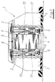
- the transport device 1 consists of a portal-shaped chassis 2 which can be moved on a transport plane via four steerable and drivable wheels 3. 1-5, the drive means and the corresponding devices for steering the wheels 3 are not shown and can be designed according to the prior art.
- the portal-shaped chassis 2 is constructed essentially in the manner of a bridge construction, with hollow steel profiles in particular being used.
- About the steerable and drivable wheels 3 can Portal-shaped chassis 2 of the transport device 1 can be moved over a sheet stack 5 located on a transport pallet 4 such that it is located exactly below the opening formed by the portal-shaped chassis 2.
- Sensor means (not shown) can be provided, by means of which the transport device 1 can be moved exactly into a precisely provided position with respect to the sheet stack 5 or the transport pallet 4.
- support members 6 are arranged vertically at their lower ends, which can be used to grasp and lift the sheet stack 5 by means of the transport pallet 4.
- Each transport member 6 is attached to a chain 7 according to its vertically movable mounting with respect to the portal frame of the chassis 2.
- a lifting device 8 is arranged which engages the four ends of the chains 7 and moves them uniformly by predetermined distances, so that the four support members 6 move simultaneously and by the same Move distances in the vertical guide of the portal-shaped chassis 2.
- the lifting device consists, for example, of a hydraulically actuated lifting cylinder with two piston rods, each piston rod being articulated via a bridge to two ends of the chains 7.
- the lifting device 8 can also be provided in connection with the chains 7.
- each support member 6 has, for example, a pneumatically or hydraulically actuated bolt which, in an extended position, grips under the surface of the transport pallet 4 and is retracted from the area of the underside of the transport pallet 4 in a retracted basic position .
- the bolts 9 are the Support members 6 extended and carry the transport pallet 4 along with the sheet stack 5 located thereon. The bolts can be movable via electromechanical lifting spindles.
- the clamping members 10 provided according to the invention are each formed as two surfaces, which act on the opposite outer sides of the sheet stack 5, for which purpose these clamping members 10 are suspended on the opposite sides of the portal-shaped chassis 2 via a pair of isosceles crank handles 11 (motion scissors) are.
- one end of the rods of the push crank 11 is articulated on the chassis 2 or on the flat clamping element 10 and is movably guided with the other end in a straight guide on the chassis 2 or on the clamping element 10.
- a pair of rods of the push cranks 11 is connected to one another by means of a joint.
- each push crank 11 is actuated pneumatically or hydraulically in a known manner, for example by a double-acting working cylinder (not shown).
- the double-acting working cylinder (not shown) for actuating the push crank 11 is supported with one end on the chassis 2 and with the other end in the region of the straight guide of the push crank linkage.
- the contact force of the clamping members 10 with respect to the outside of the sheet stack 5 can thus be made variable, so that deformations in the edge area or other damage can be avoided, particularly in the case of very sensitive sheet materials.
- the surfaces of the clamping members 10 can also be covered with a soft or resilient material. Pressure sensors can also detect and control the pressing force.
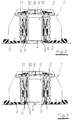
- the operation of the transport device 1 according to the invention is shown in four steps. 2, the portal-shaped chassis 2 of the transport device 1 was moved over the sheet stack located on the transport pallet 4 such that the sheet stack 5 completely and centrally located below the opening formed by the portal-shaped chassis 2. This is achieved in that the transport device 1 is first moved laterally next to the sheet stack 5 and then by swiveling the wheels 3 through 90 ° perpendicular to the previous direction of travel over the sheet stack 5. This wheel position is also indicated in FIGS. 2-5.
- the transport device 1 is a driverless vehicle.
- FIG. 4 shows the stack of sheets 5 lifted over the transport pallet 4 after the lifting device 8 has lifted the supporting members 6 over the chains 7.
- the adjusting means assigned to the pushing cranks 11 are actuated, so that the two clamping members 10 are pressed onto the two opposite sides of the sheet stack 5 facing the inside of the portal-shaped chassis 2.
- the sheet stack 5 can now be moved by means of the transport device 1, wherein a direction of travel is preferably chosen which runs parallel to the representation levels of FIGS. 1 to 5. This is done by swiveling back the wheels 3 of the transport device 1 accordingly.
- the individual sheets of the stack are secured against slipping even in the event of greater accelerations, decelerations and shocks to the transport device 1.
- the type of stack securing according to the invention even allows the sheet stack 5 to be conveyed over an inclined plane or ramp by means of the transport device 1.
- the sheet stack does not have to be removed from or placed on a flat floor - the depositing of a sheet stack 5 is carried out in the reverse order analogous to the previously described recording process - but a sheet stack 5 with the transport pallet 4 can also be used removed from a roller conveyor or picked up by one.
- the transport device 1 according to the invention with the portal-shaped chassis 2 is then moved over the roller conveyor such that the opening formed by the portal-shaped chassis 2 lies above the roller conveyor.
- the transport pallet 4 loaded with the sheet stack is raised until the underside of the transport pallet 4 is at a sufficient distance from the top of the roller conveyor.
- the driverless transport vehicle is then driven over the roller conveyor by swiveling the wheels through 90 ° and the transport pallet is lowered.
Landscapes
- Engineering & Computer Science (AREA)
- Mechanical Engineering (AREA)
- Stacking Of Articles And Auxiliary Devices (AREA)
- Sheets, Magazines, And Separation Thereof (AREA)
- Pallets (AREA)
Applications Claiming Priority (2)
| Application Number | Priority Date | Filing Date | Title |
|---|---|---|---|
| DE4331605A DE4331605C2 (de) | 1993-09-17 | 1993-09-17 | Transportfahrzeug für auf Paletten aufgestapeltes bogenförmiges Material |
| DE4331605 | 1993-09-17 |
Publications (2)
| Publication Number | Publication Date |
|---|---|
| EP0644143A1 true EP0644143A1 (fr) | 1995-03-22 |
| EP0644143B1 EP0644143B1 (fr) | 1997-10-29 |
Family
ID=6497929
Family Applications (1)
| Application Number | Title | Priority Date | Filing Date |
|---|---|---|---|
| EP94112472A Expired - Lifetime EP0644143B1 (fr) | 1993-09-17 | 1994-08-10 | Transporteur pour matériaux en forme de feuilles empilés sur des palettes |
Country Status (3)
| Country | Link |
|---|---|
| EP (1) | EP0644143B1 (fr) |
| AT (1) | ATE159693T1 (fr) |
| DE (2) | DE4331605C2 (fr) |
Cited By (2)
| Publication number | Priority date | Publication date | Assignee | Title |
|---|---|---|---|---|
| CN104924451A (zh) * | 2015-06-01 | 2015-09-23 | 中原工学院 | 落钢筋网装置 |
| CN110255200A (zh) * | 2019-06-28 | 2019-09-20 | 中集新型环保材料股份有限公司 | 坯板输送堆叠设备及坯板输送堆叠的方法 |
Families Citing this family (3)
| Publication number | Priority date | Publication date | Assignee | Title |
|---|---|---|---|---|
| DE10133815A1 (de) | 2001-07-16 | 2003-02-13 | Trepel Airport Equipment Gmbh | Flugzeugbeladevorrichtung |
| DE102007008691A1 (de) * | 2007-02-20 | 2008-08-21 | Behr, Uwe | System zum Transportieren von Gegenständen |
| CN104609237B (zh) * | 2014-12-10 | 2017-05-31 | 中原工学院 | 多连杆机构装板机 |
Citations (3)
| Publication number | Priority date | Publication date | Assignee | Title |
|---|---|---|---|---|
| US2069424A (en) * | 1934-02-10 | 1937-02-02 | Rudolph R Seft | Sheet stacking apparatus |
| US2788931A (en) * | 1946-03-05 | 1957-04-16 | Robert Gair Co Inc | Folding-box blanks with provision for accurate stacking |
| DE2447142A1 (de) * | 1973-10-25 | 1975-04-30 | Stobb Inc | Einrichtung und verfahren zur handhabung von einzelnen, aus aufeinanderliegenden bogen, vorzugsweise gefalzten druckbogen bestehenden stapeln, von denen die bogen in einer anlegerstation einzeln entnommen und zwecks bildung von buechern, zeitschriften o.dgl. zusammengetragen werden |
Family Cites Families (5)
| Publication number | Priority date | Publication date | Assignee | Title |
|---|---|---|---|---|
| DD217494B1 (de) * | 1983-09-14 | 1987-03-04 | Oranienburg Infrarot Veb | Einrichtung zum bewegen von gegenstaenden in zwei richtungen |
| US4726729A (en) * | 1986-05-02 | 1988-02-23 | Cascade Corporation | Electric motor-actuated load clamp with clamping force control |
| DE3714849C1 (en) * | 1987-05-05 | 1988-09-29 | Ernst Dipl-Kaufm Dr Ju Miebach | Industrial trucks, in particular pallet and forklift trucks, unmanned vehicles |
| DE4111523A1 (de) * | 1991-04-09 | 1992-10-15 | Fraunhofer Ges Forschung | Flurfoerderfahrzeug |
| IT1257750B (it) * | 1992-02-24 | 1996-02-13 | Gd Spa | Unita' robottizzata per il trasporto di articoli su pallet |
-
1993
- 1993-09-17 DE DE4331605A patent/DE4331605C2/de not_active Expired - Fee Related
-
1994
- 1994-08-10 EP EP94112472A patent/EP0644143B1/fr not_active Expired - Lifetime
- 1994-08-10 DE DE59404464T patent/DE59404464D1/de not_active Expired - Fee Related
- 1994-08-10 AT AT94112472T patent/ATE159693T1/de not_active IP Right Cessation
Patent Citations (3)
| Publication number | Priority date | Publication date | Assignee | Title |
|---|---|---|---|---|
| US2069424A (en) * | 1934-02-10 | 1937-02-02 | Rudolph R Seft | Sheet stacking apparatus |
| US2788931A (en) * | 1946-03-05 | 1957-04-16 | Robert Gair Co Inc | Folding-box blanks with provision for accurate stacking |
| DE2447142A1 (de) * | 1973-10-25 | 1975-04-30 | Stobb Inc | Einrichtung und verfahren zur handhabung von einzelnen, aus aufeinanderliegenden bogen, vorzugsweise gefalzten druckbogen bestehenden stapeln, von denen die bogen in einer anlegerstation einzeln entnommen und zwecks bildung von buechern, zeitschriften o.dgl. zusammengetragen werden |
Cited By (3)
| Publication number | Priority date | Publication date | Assignee | Title |
|---|---|---|---|---|
| CN104924451A (zh) * | 2015-06-01 | 2015-09-23 | 中原工学院 | 落钢筋网装置 |
| CN110255200A (zh) * | 2019-06-28 | 2019-09-20 | 中集新型环保材料股份有限公司 | 坯板输送堆叠设备及坯板输送堆叠的方法 |
| CN110255200B (zh) * | 2019-06-28 | 2024-05-28 | 徐州中集新材科技发展有限公司 | 坯板输送堆叠设备及坯板输送堆叠的方法 |
Also Published As
| Publication number | Publication date |
|---|---|
| EP0644143B1 (fr) | 1997-10-29 |
| DE59404464D1 (de) | 1997-12-04 |
| ATE159693T1 (de) | 1997-11-15 |
| DE4331605C2 (de) | 1995-11-30 |
| DE4331605A1 (de) | 1995-03-30 |
Similar Documents
| Publication | Publication Date | Title |
|---|---|---|
| EP1847490B1 (fr) | Dispositif et procédé de palettisation et/ou de dépalettisation automatique de réservoirs | |
| DE3718601C2 (fr) | ||
| DD292205A5 (de) | Palettierroboter | |
| EP0482406A1 (fr) | Dispositif de maniement pour articles tels que cartons | |
| EP0560112A1 (fr) | Dispositif pour amener des couches intercalaires à une pile | |
| DE4213301C2 (de) | Vorrichtung und Verfahren zur Entnahme von oben offenen gestapelten Kästen | |
| DE19926822B4 (de) | Plattenwechselvorrichtung | |
| DE19501637C2 (de) | Palettiervorrichtung | |
| EP0644143B1 (fr) | Transporteur pour matériaux en forme de feuilles empilés sur des palettes | |
| WO2015124750A2 (fr) | Dispositif et procédé de transbordement d'unités de chargement | |
| DE2447142C2 (de) | Verfahren und Einrichtung zur Handhabung von einzelnen, aus aufeinanderliegenden Bogen, vorzugsweise gefalzten Druckbogen bestehenden Stapeln, bei denen die Bogen in einer Anlegerstation einzeln entnommen und zwecks Bildung von Büchern, Zeitschriften o.dgl. zusammengetragen werden | |
| EP0161513A1 (fr) | Dispositif pour l'empilage de palettes chargées avec des objets, notamment des sacs larges | |
| DE2925426C2 (de) | Vorrichtung zum Stapeln von Paletten | |
| DE2802345A1 (de) | Vorrichtung zum umschlagen von ladeeinheiten | |
| EP0283042B1 (fr) | Méthode et dispositif pour la palettisation de couches unitaires | |
| DE102005001250B4 (de) | Wendeeinrichtung für Halbfertigteile | |
| DE19607563C1 (de) | Handhabungseinrichtung, insbesondere Palettenumsetzeinrichtung | |
| DE3033682C2 (de) | Vorrichtung zum Be- und/oder Entladen aus übereinandergestapelter Wandanordnung in lineare Transportanordnung | |
| DE20303962U1 (de) | Vorrichtung zur Handhabung von Kartonagenbündeln | |
| DE29712663U1 (de) | Vorrichtung zum Stapeln und Entstapeln | |
| DE4013172A1 (de) | Verfahren und vorrichtung zum beschicken von bogenanlegern mit von paletten getragenen bogenstapeln und abfuehren der paletten | |
| EP0210172B1 (fr) | Dispositif pour empiler des pieces a paroi mince | |
| DE10030796A1 (de) | Verfahren für das Umsetzen eines Plattenstapels und Hilfsmittel zur Durchführung des Verfahrens | |
| DE2311871C3 (de) | Vorrichtung zum ausgerichteten Auslegen von Palettenreihen | |
| DE19838346A1 (de) | Fördersystem mit einer Stapel- und Entstapelvorrichtung für Paletten |
Legal Events
| Date | Code | Title | Description |
|---|---|---|---|
| PUAI | Public reference made under article 153(3) epc to a published international application that has entered the european phase |
Free format text: ORIGINAL CODE: 0009012 |
|
| 17P | Request for examination filed |
Effective date: 19940902 |
|
| AK | Designated contracting states |
Kind code of ref document: A1 Designated state(s): AT CH DE FR GB LI |
|
| 17Q | First examination report despatched |
Effective date: 19960228 |
|
| GRAG | Despatch of communication of intention to grant |
Free format text: ORIGINAL CODE: EPIDOS AGRA |
|
| GRAH | Despatch of communication of intention to grant a patent |
Free format text: ORIGINAL CODE: EPIDOS IGRA |
|
| GRAH | Despatch of communication of intention to grant a patent |
Free format text: ORIGINAL CODE: EPIDOS IGRA |
|
| GRAA | (expected) grant |
Free format text: ORIGINAL CODE: 0009210 |
|
| AK | Designated contracting states |
Kind code of ref document: B1 Designated state(s): AT CH DE FR GB LI |
|
| REF | Corresponds to: |
Ref document number: 159693 Country of ref document: AT Date of ref document: 19971115 Kind code of ref document: T |
|
| REG | Reference to a national code |
Ref country code: CH Ref legal event code: NV Representative=s name: E. BLUM & CO. PATENTANWAELTE Ref country code: CH Ref legal event code: EP |
|
| ET | Fr: translation filed | ||
| GBT | Gb: translation of ep patent filed (gb section 77(6)(a)/1977) |
Effective date: 19971031 |
|
| REF | Corresponds to: |
Ref document number: 59404464 Country of ref document: DE Date of ref document: 19971204 |
|
| PLBE | No opposition filed within time limit |
Free format text: ORIGINAL CODE: 0009261 |
|
| STAA | Information on the status of an ep patent application or granted ep patent |
Free format text: STATUS: NO OPPOSITION FILED WITHIN TIME LIMIT |
|
| 26N | No opposition filed | ||
| PGFP | Annual fee paid to national office [announced via postgrant information from national office to epo] |
Ref country code: GB Payment date: 20010713 Year of fee payment: 8 |
|
| PGFP | Annual fee paid to national office [announced via postgrant information from national office to epo] |
Ref country code: AT Payment date: 20010725 Year of fee payment: 8 |
|
| REG | Reference to a national code |
Ref country code: GB Ref legal event code: IF02 |
|
| PGFP | Annual fee paid to national office [announced via postgrant information from national office to epo] |
Ref country code: CH Payment date: 20020717 Year of fee payment: 9 |
|
| PGFP | Annual fee paid to national office [announced via postgrant information from national office to epo] |
Ref country code: DE Payment date: 20020809 Year of fee payment: 9 |
|
| PG25 | Lapsed in a contracting state [announced via postgrant information from national office to epo] |
Ref country code: GB Free format text: LAPSE BECAUSE OF NON-PAYMENT OF DUE FEES Effective date: 20020810 Ref country code: AT Free format text: LAPSE BECAUSE OF NON-PAYMENT OF DUE FEES Effective date: 20020810 |
|
| PGFP | Annual fee paid to national office [announced via postgrant information from national office to epo] |
Ref country code: FR Payment date: 20020812 Year of fee payment: 9 |
|
| GBPC | Gb: european patent ceased through non-payment of renewal fee |
Effective date: 20020810 |
|
| PG25 | Lapsed in a contracting state [announced via postgrant information from national office to epo] |
Ref country code: LI Free format text: LAPSE BECAUSE OF NON-PAYMENT OF DUE FEES Effective date: 20030831 Ref country code: CH Free format text: LAPSE BECAUSE OF NON-PAYMENT OF DUE FEES Effective date: 20030831 |
|
| PG25 | Lapsed in a contracting state [announced via postgrant information from national office to epo] |
Ref country code: DE Free format text: LAPSE BECAUSE OF NON-PAYMENT OF DUE FEES Effective date: 20040302 |
|
| REG | Reference to a national code |
Ref country code: CH Ref legal event code: PL |
|
| PG25 | Lapsed in a contracting state [announced via postgrant information from national office to epo] |
Ref country code: FR Free format text: LAPSE BECAUSE OF NON-PAYMENT OF DUE FEES Effective date: 20040430 |
|
| REG | Reference to a national code |
Ref country code: FR Ref legal event code: ST |