EP0644351B1 - Anneau de serrage pour ressort pneumatique - Google Patents
Anneau de serrage pour ressort pneumatique Download PDFInfo
- Publication number
- EP0644351B1 EP0644351B1 EP94114210A EP94114210A EP0644351B1 EP 0644351 B1 EP0644351 B1 EP 0644351B1 EP 94114210 A EP94114210 A EP 94114210A EP 94114210 A EP94114210 A EP 94114210A EP 0644351 B1 EP0644351 B1 EP 0644351B1
- Authority
- EP
- European Patent Office
- Prior art keywords
- annular
- clamp ring
- air spring
- projections
- sleeve
- Prior art date
- Legal status (The legal status is an assumption and is not a legal conclusion. Google has not performed a legal analysis and makes no representation as to the accuracy of the status listed.)
- Expired - Lifetime
Links
- 238000007789 sealing Methods 0.000 claims description 33
- 239000013536 elastomeric material Substances 0.000 claims description 13
- 239000012530 fluid Substances 0.000 claims description 10
- 230000003014 reinforcing effect Effects 0.000 claims description 10
- 239000000463 material Substances 0.000 description 7
- 238000005096 rolling process Methods 0.000 description 4
- 238000010276 construction Methods 0.000 description 3
- 239000012528 membrane Substances 0.000 description 3
- 230000000712 assembly Effects 0.000 description 2
- 238000000429 assembly Methods 0.000 description 2
- 230000015572 biosynthetic process Effects 0.000 description 2
- 230000006835 compression Effects 0.000 description 2
- 238000007906 compression Methods 0.000 description 2
- 230000000694 effects Effects 0.000 description 2
- 230000035939 shock Effects 0.000 description 2
- 229910052782 aluminium Inorganic materials 0.000 description 1
- XAGFODPZIPBFFR-UHFFFAOYSA-N aluminium Chemical compound [Al] XAGFODPZIPBFFR-UHFFFAOYSA-N 0.000 description 1
- 238000004873 anchoring Methods 0.000 description 1
- 230000009172 bursting Effects 0.000 description 1
- 230000002542 deteriorative effect Effects 0.000 description 1
- 238000003754 machining Methods 0.000 description 1
- 238000012423 maintenance Methods 0.000 description 1
- 230000014759 maintenance of location Effects 0.000 description 1
- 229910052751 metal Inorganic materials 0.000 description 1
- 239000002184 metal Substances 0.000 description 1
- 239000004033 plastic Substances 0.000 description 1
- 230000002028 premature Effects 0.000 description 1
- 239000007787 solid Substances 0.000 description 1
- 230000003068 static effect Effects 0.000 description 1
- 230000007704 transition Effects 0.000 description 1
- 239000011800 void material Substances 0.000 description 1
Images


Classifications
-
- F—MECHANICAL ENGINEERING; LIGHTING; HEATING; WEAPONS; BLASTING
- F16—ENGINEERING ELEMENTS AND UNITS; GENERAL MEASURES FOR PRODUCING AND MAINTAINING EFFECTIVE FUNCTIONING OF MACHINES OR INSTALLATIONS; THERMAL INSULATION IN GENERAL
- F16F—SPRINGS; SHOCK-ABSORBERS; MEANS FOR DAMPING VIBRATION
- F16F9/00—Springs, vibration-dampers, shock-absorbers, or similarly-constructed movement-dampers using a fluid or the equivalent as damping medium
- F16F9/02—Springs, vibration-dampers, shock-absorbers, or similarly-constructed movement-dampers using a fluid or the equivalent as damping medium using gas only or vacuum
- F16F9/04—Springs, vibration-dampers, shock-absorbers, or similarly-constructed movement-dampers using a fluid or the equivalent as damping medium using gas only or vacuum in a chamber with a flexible wall
- F16F9/0454—Springs, vibration-dampers, shock-absorbers, or similarly-constructed movement-dampers using a fluid or the equivalent as damping medium using gas only or vacuum in a chamber with a flexible wall characterised by the assembling method or by the mounting arrangement, e.g. mounting of the membrane
- F16F9/0463—Springs, vibration-dampers, shock-absorbers, or similarly-constructed movement-dampers using a fluid or the equivalent as damping medium using gas only or vacuum in a chamber with a flexible wall characterised by the assembling method or by the mounting arrangement, e.g. mounting of the membrane with separate crimping rings
Definitions
- the invention relates to clamping means and more particularly to the clamping means adapted to affix a resilient elastomeric sleeve member to a relatively rigid piston member or end cap of an air spring.
- the invention relates to a clamp ring assembly employing a clamping ring having at least a pair of recesses on the inner diameter thereof which coact with a corresponding member of projections on the outer diameter of the piston member or end cap to positionally locate the clamping ring on the piston member and to effectively seal the open end of the elastomeric sleeve therebetween.
- the air spring usually consists of a flexible rubber sleeve or bellows containing a supply of compressible fluid and has one or more pistons movable with respect to the flexible sleeve.
- the piston causes compression and expansion of the fluid within the sleeve as the sleeve compresses and expands as the vehicle experiences the road shock.
- the spring sleeve is formed of a flexible elastomeric material containing reinforcing cords, and permits the piston to move axially with respect to another piston or end cap secured within open ends of the sleeve.
- the open ends of the sleeves are sealingly connected to the piston and/or opposite end cap, and the integrity of this connection is always one of the important and major aspects in producing an efficient and maintenance free air spring.
- Another problem with existing air springs, and in particular, the clamp ring therefore, is that the clamp ring will move in its clamped position under dynamic air spring conditions causing movement of the clamped elastomeric material therebetween tending to loosen the sealing engagement and deteriorating the clamp integrity and causing ultimate air spring leakage and failure. This ring movement is especially critical during the jounce or collapsing stroke.
- Another problem with existing air springs and the clamping of the elastomeric sleeve ends to the piston member and/or end cap is to secure a sufficiently tight seal to be able to withstand high fluid pressures contained in the fluid chamber without premature leakage or bursting even upon experiencing severe air spring movement and being exposed to the harsh environments on the undercarriage of a vehicle.
- U.S. Patent No. 3,788,628 discloses a pneumatic spring-type system which includes a structure for anchoring the inner ends of a flexible rolling sleeve.
- the sleeve is positioned between surfaces characterized by having a saw-toothed shape with a circumferential groove and rib on an inner circumferential surface and two ribs on an outer circumferential surface.
- the opposite sides of the grooves converge at predefined angles with predetermined and matching radius of curvatures, the combination of which provides a gripping action to hold the flexible sleeve firmly in place by means of the saw-tooth design, in cooperation with the matching recess of the ring and sleeve flange.
- U.S. Patent No. 3,870,286 shows a fluid spring wherein the ends of the rolling sleeve are secured by annular clamping rings which engage against the internal surface of the sleeve.
- the clamping ring secures the rolling sleeve to the working cylinder.
- the clamping ring contains an annular groove deformation by which the rolling sleeve is held in place by virtue of this interacting groove-shaped design in combination with the clamping force exerted by the ring.
- U.S. Patent No. 4,489,474 relates to means for connecting a tubular flexible member to a piston which includes a recess near the piston end to which is secured a flexible member.
- the flexible member is wrapped over and around a ring-shaped fitting which secures the flexible member to the piston.
- the piston comprises a circumferentially extending recess adjacent to its end with the flexible sleeve being positioned and substantially filling the recess of the piston.
- the ring-shaped fitting is a conventional swaged ring and the end portion of the flexible member is trimmed from the portion extending from the piston ring with the flexible member substantially filling the recess of the shoulder of the piston.
- the piston employs a serrated edge to assist in griping of the flexible member.
- U.S. Patent No. 4,573,692 discloses an assembly for sealing two members, one of which has a cylindrical surface which supports the seal, wherein a sealing lip is provided to bear against the second member.
- a cylindrical surface supports the seal which comprises a hollow-cylindrical body having a lip which extends outwardly from the body with an elastomeric band circling the body to hold it firmly in place.
- the cylindrical surface contains a recess which extends circumferentially around the surface and receives a matching projecting element of the seal which extends from the inside diameter of the cylindrical body.
- British Patent No. 199,789 discloses a metal securing band which grips a diaphragm and forces it against a tapered end portion of a tubular member.
- U.S. Patent No. 4,718,650 shows an air spring in which the ends of the flexible sleeves are connected to the sealing surfaces of a pair of axially spaced pistons by swaged or crimped clamping rings.
- the piston clamping surfaces are formed with serrations to assist the retention of the elastomeric material when forced therein by the clamping rings.
- Another known prior art air spring construction includes a radially extending shoulder formed on the piston member on which the clamping ring seats and sealingly clamps the cut end of the flexible sleeve against a plurality of uniformly raised ribs formed on the axially extending sealing surface of the piston member adjacent the annular shoulder.
- the clamp ring is not positively positioned on the annular shoulder, and is free to move in an upward axial direction upon the air spring experiencing severe jounce or extended positioning.
- Objectives of the invention include providing an improved clamp ring assembly for air springs, primarily used for motor vehicles, having a piston at one end and an end cap at an axially spaced opposite end, with a flexible elastomeric sleeve extending therebetween and clamped against the respective end cap and piston member by clamp rings to form a fluid tight seal therebetween and provide an intervening pressure chamber.
- a further objective is to provide such an improved clamp ring assembly in which annular expansion grooves are formed between the projections on the piston member and end cap member sealing surfaces to permit the elastomeric material to flow therein to form bead-like holding members.
- Another objective is to provide such an improved clamp ring assembly in which the outer surface of the clamp ring generally aligns with the adjacent outer surface of the piston or end cap to provide a generally continuous surface between the clamp ring and piston member or end cap over which the elastomeric sleeve rolls, to provide a smooth interface therebetween to reduce wear on the elastomeric sleeve as it moves along the surfaces of the piston member or end cap and clamping ring during dynamic operation of the air spring.
- a further objective is to provide such an improved clamp ring assembly in which the radial distance between the outer surfaces of the annular projections of the piston and/or end member sealing surfaces is spaced from the bottom curved surfaces of the concave recesses in the clamp ring a distance generally equal to 50% of the thickness of the elastomeric sleeve to be sealingly clamped therebetween.
- Still another objective of the invention is to provide such a clamp ring assembly in which the concave recesses of the clamp ring are separated by generally flat surfaces having the same diameter as the remaining portions of the clamp ring inner surface thereby enabling the clamp ring to be formed from a ring blank having a uniform inner thickness or diameter to achieve the most efficient use of the clamp ring material and to reduce costs of constructing the clamp ring.
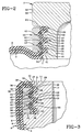
- an improved axially extending clamping surface indicated generally at 10 is formed on a reduced diameter upper end portion 11 of piston member 3, shown in detail in FIG. 3.
- Clamping surface 10 is connected to conical outer wall 4 of the piston member by a radially extending shoulder 12 and a curved corner 13.
- the open outer end of piston end portion 11 has a radially extending flat surface 14 which terminates in an annular stepped surface having first and second annular portions indicated at 15 and 16, respectively, with portion 15 having a larger diameter than portion 16.
- clamping surface 10 includes a pair of annular radially extending clamping projections 19 and 20.
- Annular projections 19 and 20 are of equal diameters and preferably terminate in convex outer ends 21 and 22, respectively.
- Projections 19 and 20 are separated by an annular material expansion groove 23 which has an inwardly tapered configuration formed by flat sides which terminate in a generally flat bottom surface, providing a generally truncated configuration.
- a pair of material expansion grooves 26 and 27 are formed on the other sides of projections 19 and 20, with groove 26 being formed by one tapered side of projection 19 and a generally flat radially surface 28 which merges with stepped portion 16.
- Groove 27 is formed by a tapered side of projection 20 and the innermost portion of radial shoulder 12.
- Grooves 23, 26 and 27 provide expansion areas or zones for the movement of the elastomeric material of flexible sleeve 8 therein, and provide for the formation of three bead-like members 29 which assist greatly to prevent axial pull out of the sleeve end when clamped thereon as described below.
- recesses 33 and 34 of clamp ring 32 radially align and cooperate with convex projections 19 and 20 of piston clamping surface 10 to positionally align the clamp ring on the piston sealing surface for receiving the open end of flexible sleeve 8 therebetween.
- circumferential end surface 37 of the clamp ring seats upon or is located closely adjacent to annular shoulder 12, which prevents movement of clamp ring 32 in the downward axial direction in reference to FIGS. 1 and 3, during the operation of the air spring. This is especially critical during the jounce of collapse position of the air spring in which piston 3 moves axially towards end cap 2.
- convex outer ends 21 and 22 of projections 19 and 20 are spaced from the curved bottom surfaces of clamp ring recesses 33 and 34 a distance within the range of 40% to 60% of the thickness of sleeve 8, which is represented by arrow A in FIG. 3, to provide a pair of spaced pinch areas 42 and 43 on the elastomeric sleeve material.
- the distance between outer ends 21 and 22 and the bottom curved surfaces of recesses 33 and 34 is 50% of the thickness of sleeve 8.
- top annular portion of inner clamp ring surface 35 is spaced from a rounded corner 30 which connects radial surface 28 with annular portion 16, and is separated therefrom by a distance indicated by arrow B, which again is generally equal to distances A described above, that is between 40% and 60% of the material thickness of sleeve 8 to provide another pinch area.
- expansion grooves 23, 26 and 27 receive the elastomeric material of sleeve 8 as it is squeezed between the bottom surfaces of recesses 33 and 34 and ends 21 and 22 of projections 19 and 20, which further assists in providing a tight clamping engagement between clamp ring 32 and piston clamping surface 10.
- the volume provided by the three expansion grooves preferably is greater than the volume of the rubber which is squeezed thereinto, which will permit annular void areas at the bottoms of grooves 23, 26 and 27 to ensure that the desired clamping force is achieved between the projections and ring recesses.
- end cap 2 is formed with an annular axially extending body 44 having an outer axially extending annular sealing surface indicated generally at 45. Sealing surface 45 is formed with a pair of projections 46 and 47 similar to piston projections 19 and 20, and three material expansion grooves 48, 49 and 50, similar to expansion grooves 23, 26 and 27 of piston 3. End cap 2 preferably is provided with a radially extending annular top flange 52 having an annular radial shoulder 53 which communicates with end expansion groove 50.
- end cap sealing surface 45 in cooperation with clamp ring 55 is similar to that described above with respect to piston clamping surface 10 and clamp ring 32.
- outer annular surface 56 of end cap flange 52 axially aligns with outer annular surface 57 of clamp ring 55 to provide a generally continuous surface over which flexible sleeve 8 will move when the air spring is in the jounce position to avoid any sharp bends and to provide continuous transition between the aligned surfaces in a similar manner as provided by outer surface 38 of clamp ring 32 and outer wall 4 of the piston member as shown in FIG. 3.
- annular projections 19 and 20, and projections 46 and 47 in cooperation with the bottom surfaces of the corresponding concave recesses formed in clamp rings 32 and 55, provides increased holding power for maintaining the trapped sleeve ends, than that provided by the pair of spaced pinch zones provided by the single projection and recess and pair of adjacent projections of the clamp ring assembly of Patent No. 4,899,995. This increased holding power is believed to occur due to the additional direction changes of the sleeve material and in particular by changes of direction of the reinforcing cords 9 embedded therein.
- this groove configuration in the piston and end cap sealing surfaces provides for the formation of three bead-like members 29 which further assist in trapping the sleeve ends in their respective end members and further resist pull-out, even when a relatively high internal pressure is placed within fluid chamber 18.
- the improved clamp ring assembly for an air spring is simplified, provides an effective, safe, inexpensive, and efficient assembly which achieves all the enumerated objectives, provides for eliminating difficulties encountered with prior clamping assemblies, and solves problems and obtains new results in the art.
Landscapes
- Engineering & Computer Science (AREA)
- General Engineering & Computer Science (AREA)
- Mechanical Engineering (AREA)
- Fluid-Damping Devices (AREA)
- Vehicle Body Suspensions (AREA)
Claims (10)
- Dans un ressort pneumatique (1) ayant une paire d'organes d'extrémité (2, 3) adaptés pour être montés en des emplacements globalement espacés axialement, une douille flexible (8) constituée d'un matériau élastomère contenant des cordes de renforcement (9) et ayant des extrémités ouvertes placées en contact étanche avec les organes d'extrémité en constituant entre eux une chambre à fluide (18), une surface d'étanchéité (10, 45) annulaire s'étendant axialement, constituée d'au moins l'un desdits organes d'extrémité, d'un anneau de serrage annulaire (32, 55) ayant une surface de serrage intérieur (35) s'étendant axialement, placée concentriquement par rapport à la surface d'étanchéité annulaire dudit organe d'extrémité, pour serrer entre eux de façon étanche une extrémité de ladite douille flexible, et un épaulement annulaire (12, 53) s'étendant radialement vers l'extérieur, formé à une extrémité de la surface d'étanchéité annulaire dudit organe d'extrémité, afin de servir de butée à l'anneau de serrage afin de limiter le déplacement dudit anneau de serrage dans la direction axiale pendant le fonctionnement du ressort pneumatique, caractérisé en ce que la surface d'étanchéité annulaire (10, 45) est constituée d'une paire de saillies annulaires (19, 20, 46, 47) espacées axialement, s'étendant radialement vers l'extérieur, et en ce que l'anneau de serrage (32, 55) est constitué d'une paire de cavités (33, 34), chaque cavité coopérant avec une saillie respective des saillies annulaires, pour placer en position ledit anneau par rapport audit organe d'extrémité et pour constituer une paire d'aires de pincement (42, 43) espacées axialement, pour assurer le serrage entre elles de la douille flexible et pour modifier la direction de déplacement des cordes de renforcement dans la douille serrée, et en ce qu'au moins trois gorges (23, 26, 27, 48, 49, 50) sont ménagées dans la surface d'étanchéité dudit organe d'extrémité, constituant des zones d'expansion prévues pour recevoir en leur sein le matériau élastomère de la douille, une desdites gorges (23, 48) étant en position intermédiaire vis-à-vis de la paire de saillies, les deux autres gorges (26, 27, 49, 50) étant placées sur les autres côtés desdites saillies.
- Le ressort pneumatique selon la revendication 1, caractérisé en ce que les diamètres des deux saillies annulaires (19, 20, 46, 47) sont identiques.
- Le ressort pneumatique selon la revendication 1, caractérisé en ce que les saillies annulaires s'achèvent en des extrémités extérieures (21, 23) espacées radialement des surfaces de fond des cavités (33, 34) concaves à une distance située dans la plage allant de 40 % à 60 % de l'épaisseur de la douille flexible.
- Le ressort pneumatique selon la revendication 3, caractérisé en ce que les extrémités extérieures (21, 23) des saillies annulaires (19, 20, 46, 47) ont une incurvation convexe.
- Le ressort pneumatique selon la revendication 1, caractérisé en ce que chacune desdites gorges d'expansion s'étend radialement vers l'intérieur dans l'anneau de serrage (32, 55), globalement sur la même distance que l'autre gorge.
- Le ressort pneumatique selon la revendication 1, caractérisé en ce que les cavités (33, 34) de l'anneau de serrage ont une incurvation concave.
- Le ressort pneumatique selon la revendication 1, caractérisé en ce qu'une extrémité de la surface d'étanchéité (10, 45) de l'organe d'extrémité, opposée à l'épaulement annulaire, s'achève en une surface étagée annulaire et en ce que ladite surface étagée annulaire a des première (15, 54) et deuxième (16, 51) parties annulaires, ladite première partie (15, 54) ayant un diamètre globalement égal au diamètre de la paire de saillies annulaires.
- Le ressort pneumatique selon la revendication 7, caractérisé en ce que la deuxième partie de la surface étagée annulaire constitue une aire de pincement (B, C) avec un bord intérieur de l'anneau de serrage.
- Le ressort pneumatique selon la revendication 1, caractérisé en ce que les deux cavités (33, 34) sont séparées par une surface annulaire (40) globalement plate faisant partie de la surface de serrage intérieure (35) s'étendant axialement de l'anneau de serrage, ladite surface plate étant sensiblement du même diamètre que ladite surface intérieure, s'étendant axialement, de l'anneau de serrage.
- Le ressort pneumatique selon la revendication 1, caractérisé en ce que ledit organe d'extrémité est un piston (3) ayant un corps; l'épaulement annulaire (12) s'achève en le corps de piston par un angle arrondi (13); et l'anneau de serrage (32) a une surface extérieure annulaire (38) s'étendant axialement, qui est globalement alignée avec ledit angle incurvé du corps pour constituer une surface pratiquement continue sur laquelle la douille flexible peut rouler pendant le fonctionnement du ressort pneumatique.
Applications Claiming Priority (2)
| Application Number | Priority Date | Filing Date | Title |
|---|---|---|---|
| US123825 | 1993-09-20 | ||
| US08/123,825 US5374037A (en) | 1993-09-20 | 1993-09-20 | Clamp ring assembly for air spring |
Publications (2)
| Publication Number | Publication Date |
|---|---|
| EP0644351A1 EP0644351A1 (fr) | 1995-03-22 |
| EP0644351B1 true EP0644351B1 (fr) | 1996-07-24 |
Family
ID=22411119
Family Applications (1)
| Application Number | Title | Priority Date | Filing Date |
|---|---|---|---|
| EP94114210A Expired - Lifetime EP0644351B1 (fr) | 1993-09-20 | 1994-09-09 | Anneau de serrage pour ressort pneumatique |
Country Status (7)
| Country | Link |
|---|---|
| US (1) | US5374037A (fr) |
| EP (1) | EP0644351B1 (fr) |
| JP (1) | JPH07151178A (fr) |
| BR (1) | BR9403771A (fr) |
| CA (1) | CA2132371C (fr) |
| DE (1) | DE69400330T2 (fr) |
| ES (1) | ES2089877T3 (fr) |
Families Citing this family (32)
| Publication number | Priority date | Publication date | Assignee | Title |
|---|---|---|---|---|
| US5460354A (en) * | 1994-06-24 | 1995-10-24 | Bridgestone/Firestone, Inc. | Clamp assembly for air spring |
| DE4445902A1 (de) * | 1994-12-22 | 1996-06-27 | Continental Ag | Spannringbefestigung für einen Schlauchrollbalg einer Luftfeder |
| US5941509A (en) * | 1997-04-18 | 1999-08-24 | Bridgestone/Firestone, Inc. | Clamp assembly for air actuator |
| US6036180A (en) * | 1998-02-26 | 2000-03-14 | Bridgestone/Firestone, Inc. | Tear-drop shaped clamp assembly and tapered end cap for an air spring |
| DE10103493A1 (de) * | 2000-02-17 | 2001-08-23 | Phoenix Ag | Luftfederanordnung |
| DE10105769A1 (de) * | 2000-02-28 | 2001-08-30 | Phoenix Ag | Luftfederanordnung |
| DE10050777B4 (de) * | 2000-10-13 | 2004-09-30 | Continental Aktiengesellschaft | Luftfeder und Verfahren zur Herstellung einer Luftfeder |
| WO2002084142A1 (fr) * | 2001-04-17 | 2002-10-24 | Phoenix Ag | Ensemble de suspension pneumatique |
| US6474630B1 (en) * | 2001-04-24 | 2002-11-05 | Bfs Diversified Products, Llc | Air spring swage assembly |
| DE10163818B4 (de) * | 2001-12-22 | 2020-08-20 | Contitech Luftfedersysteme Gmbh | Schlauchrollbalg-Feder |
| US6619635B1 (en) | 2002-04-08 | 2003-09-16 | Bfs Diversified Products, Llc | Air spring clamping assembly |
| DE10216750A1 (de) * | 2002-04-16 | 2003-10-30 | Contitech Luftfedersyst Gmbh | Schlauchrollbalg-Luftfeder |
| EP1388441A3 (fr) * | 2002-08-09 | 2004-03-24 | Kerler, Johann, jun. | Dispositif de réglage pneumatique de la hauteur pour véhicules |
| US6719279B1 (en) | 2002-08-21 | 2004-04-13 | Bfs Diversified Products, Llc | Air spring sleeve |
| US8306696B2 (en) | 2003-04-17 | 2012-11-06 | Driveright Holdings, Ltd. | Method and system for aligning a vehicle with an artificial horizon |
| WO2005005178A2 (fr) * | 2003-04-17 | 2005-01-20 | Bfs Diversified Products, Llc | Procede et systeme d'alignement d'un vehicule a l'arret a l'aide d'un horizon artificiel |
| DE10354574B3 (de) * | 2003-11-21 | 2005-01-27 | Contitech Luftfedersysteme Gmbh | Luftfeder mit einem wulstlosen Schlauchrollbalg |
| US7744099B2 (en) * | 2004-11-04 | 2010-06-29 | Driveright Holdings, Ltd. | Method and system for adjusting a vehicle aligned with an artificial horizon |
| DE102004054205A1 (de) * | 2004-11-10 | 2006-05-11 | Zf Friedrichshafen Ag | Luftfeder |
| DE202005004099U1 (de) * | 2005-03-11 | 2006-10-05 | Kerler Jun., Johann | Pneumatische Höhenverstelleinrichtung bzw. Feder für Kraftfahrzeuge |
| US7325794B2 (en) | 2005-06-06 | 2008-02-05 | Bfs Diversified Products, Llc | Air spring assembly and method |
| US7404547B2 (en) * | 2005-07-27 | 2008-07-29 | Bfs Diversified Products, Llc | Multi-component end member assembly and air spring assembly including the same |
| JP2007255587A (ja) * | 2006-03-23 | 2007-10-04 | Kayaba Ind Co Ltd | ダイヤフラムの連結構造 |
| US8800974B2 (en) | 2006-11-14 | 2014-08-12 | Firestone Industrial Products Company, Llc | Air spring sleeve |
| CN100443761C (zh) * | 2007-03-08 | 2008-12-17 | 中国人民解放军海军工程大学 | 高压大载荷空气弹簧 |
| DE102007055077A1 (de) * | 2007-11-16 | 2009-05-20 | Continental Aktiengesellschaft | Klemmkontur für ein druckbeaufschlagbares Bauteil und Spannmittel dafür |
| US8155835B2 (en) * | 2008-02-21 | 2012-04-10 | Driveright Holdings, Ltd. | Vehicle chassis height adjustment method and system |
| US9541150B2 (en) * | 2012-08-31 | 2017-01-10 | Firestone Industrial Products Company, Llc | End members and gas spring assemblies including same |
| DE102019110034A1 (de) * | 2019-04-16 | 2020-10-22 | Carl Freudenberg Kg | Dichtungsbalg |
| US11267305B2 (en) * | 2019-12-09 | 2022-03-08 | Continental Automotive Systems, Inc. | Double rolling lobe crimpless guide tube |
| KR102585126B1 (ko) * | 2022-03-23 | 2023-10-04 | 장윤호 | 충격완화효율을 높인 에어스프링 |
| KR20240030164A (ko) * | 2022-08-30 | 2024-03-07 | 주식회사 일진 | 차량용 에어 스프링 어셈블리 |
Family Cites Families (16)
| Publication number | Priority date | Publication date | Assignee | Title |
|---|---|---|---|---|
| NL48460C (fr) * | 1937-03-30 | |||
| US3819166A (en) * | 1972-10-12 | 1974-06-25 | Gen Motors Corp | Gas bladder for combination liquid gas suspension device |
| US3788628A (en) * | 1972-11-10 | 1974-01-29 | Wright Barry Corp | Pneumatic isolator |
| US4378935A (en) * | 1979-03-08 | 1983-04-05 | The Goodyear Tire & Rubber Company | Rolling lobe airspring |
| US4489474A (en) * | 1979-03-08 | 1984-12-25 | The Goodyear Tire & Rubber Company | Assembling method of rolling lobe airspring |
| US4564177A (en) * | 1983-04-21 | 1986-01-14 | The Firestone Tire & Rubber Company | Clamp for non-beaded pneumatic assemblies |
| US4629170A (en) * | 1984-06-29 | 1986-12-16 | The Goodyear Tire & Rubber Company | Dual chamber air spring |
| DE3426805A1 (de) * | 1984-07-20 | 1986-01-23 | INA Wälzlager Schaeffler KG, 8522 Herzogenaurach | Abdichtung |
| US4718650A (en) * | 1986-06-23 | 1988-01-12 | The Firestone Tire & Rubber Company | Air spring for vehicle |
| US4787607A (en) * | 1986-09-24 | 1988-11-29 | The Firestone Tire & Rubber Company | Air spring having internal sealing band and method of installing same |
| US4787606A (en) * | 1987-06-17 | 1988-11-29 | The Firestone Tire & Rubber Company | Beadless air spring |
| US4784376A (en) * | 1987-06-17 | 1988-11-15 | The Firestone Tire & Rubber Company | End cap assembly for air spring |
| US5005808A (en) * | 1987-12-01 | 1991-04-09 | The Goodyear Tire & Rubber Company | Airspring end member and airspring assembly |
| US4899995A (en) * | 1988-12-29 | 1990-02-13 | Bridgestone/Firestone, Inc. | Clamp ring assembly for air spring |
| US4852861A (en) * | 1988-12-29 | 1989-08-01 | The Firestone Tire & Rubber Company | End cap assembly for air spring |
| DE4006480A1 (de) * | 1990-03-02 | 1991-09-05 | Continental Ag | Rollbalg-luftfeder mit einem schlauchrollbalg aus elastomerem werkstoff |
-
1993
- 1993-09-20 US US08/123,825 patent/US5374037A/en not_active Expired - Lifetime
-
1994
- 1994-09-09 EP EP94114210A patent/EP0644351B1/fr not_active Expired - Lifetime
- 1994-09-09 ES ES94114210T patent/ES2089877T3/es not_active Expired - Lifetime
- 1994-09-09 DE DE69400330T patent/DE69400330T2/de not_active Expired - Lifetime
- 1994-09-19 CA CA002132371A patent/CA2132371C/fr not_active Expired - Fee Related
- 1994-09-19 BR BR9403771A patent/BR9403771A/pt not_active IP Right Cessation
- 1994-09-19 JP JP6248284A patent/JPH07151178A/ja active Pending
Also Published As
| Publication number | Publication date |
|---|---|
| CA2132371A1 (fr) | 1995-03-21 |
| BR9403771A (pt) | 1995-05-23 |
| CA2132371C (fr) | 2005-02-08 |
| DE69400330D1 (de) | 1996-08-29 |
| EP0644351A1 (fr) | 1995-03-22 |
| JPH07151178A (ja) | 1995-06-13 |
| US5374037A (en) | 1994-12-20 |
| DE69400330T2 (de) | 1996-12-12 |
| ES2089877T3 (es) | 1996-10-01 |
Similar Documents
| Publication | Publication Date | Title |
|---|---|---|
| EP0644351B1 (fr) | Anneau de serrage pour ressort pneumatique | |
| EP0378748B1 (fr) | Cloche de montage pour un ressort pneumatique | |
| EP0379667B1 (fr) | Anneau de serrage pour ressort pneumatique | |
| US4787606A (en) | Beadless air spring | |
| US4946144A (en) | External clamping band for air spring | |
| US4787607A (en) | Air spring having internal sealing band and method of installing same | |
| EP0295393B1 (fr) | Assemblage d'une plaque d'extrémité pour ressort pneumatique | |
| US5941509A (en) | Clamp assembly for air actuator | |
| US6474630B1 (en) | Air spring swage assembly | |
| US6036180A (en) | Tear-drop shaped clamp assembly and tapered end cap for an air spring | |
| US6619635B1 (en) | Air spring clamping assembly | |
| EP0264573A2 (fr) | Ressort pneumatique avec anneau d'étanchéité interne et son procédé de montage | |
| US4793598A (en) | Air spring having internal sealing band and method of installing same | |
| CA1293005C (fr) | Embout de ressort hydraulique | |
| CA2235171A1 (fr) | Ensemble bague pour actionneur a air | |
| MXPA98003033A (en) | Clamp assembly for actuator of a |
Legal Events
| Date | Code | Title | Description |
|---|---|---|---|
| PUAI | Public reference made under article 153(3) epc to a published international application that has entered the european phase |
Free format text: ORIGINAL CODE: 0009012 |
|
| 17P | Request for examination filed |
Effective date: 19950118 |
|
| AK | Designated contracting states |
Kind code of ref document: A1 Designated state(s): DE ES FR GB IT |
|
| GRAG | Despatch of communication of intention to grant |
Free format text: ORIGINAL CODE: EPIDOS AGRA |
|
| GRAH | Despatch of communication of intention to grant a patent |
Free format text: ORIGINAL CODE: EPIDOS IGRA |
|
| 17Q | First examination report despatched |
Effective date: 19951218 |
|
| GRAH | Despatch of communication of intention to grant a patent |
Free format text: ORIGINAL CODE: EPIDOS IGRA |
|
| GRAA | (expected) grant |
Free format text: ORIGINAL CODE: 0009210 |
|
| AK | Designated contracting states |
Kind code of ref document: B1 Designated state(s): DE ES FR GB IT |
|
| REF | Corresponds to: |
Ref document number: 69400330 Country of ref document: DE Date of ref document: 19960829 |
|
| ET | Fr: translation filed | ||
| ITF | It: translation for a ep patent filed | ||
| REG | Reference to a national code |
Ref country code: ES Ref legal event code: FG2A Ref document number: 2089877 Country of ref document: ES Kind code of ref document: T3 |
|
| REG | Reference to a national code |
Ref country code: ES Ref legal event code: FG2A Ref document number: 2089877 Country of ref document: ES Kind code of ref document: T3 |
|
| PLBE | No opposition filed within time limit |
Free format text: ORIGINAL CODE: 0009261 |
|
| STAA | Information on the status of an ep patent application or granted ep patent |
Free format text: STATUS: NO OPPOSITION FILED WITHIN TIME LIMIT |
|
| 26N | No opposition filed | ||
| PGFP | Annual fee paid to national office [announced via postgrant information from national office to epo] |
Ref country code: ES Payment date: 20010919 Year of fee payment: 8 |
|
| REG | Reference to a national code |
Ref country code: GB Ref legal event code: IF02 |
|
| PG25 | Lapsed in a contracting state [announced via postgrant information from national office to epo] |
Ref country code: ES Free format text: LAPSE BECAUSE OF NON-PAYMENT OF DUE FEES Effective date: 20020910 |
|
| REG | Reference to a national code |
Ref country code: GB Ref legal event code: 732E |
|
| REG | Reference to a national code |
Ref country code: ES Ref legal event code: FD2A Effective date: 20031011 |
|
| REG | Reference to a national code |
Ref country code: FR Ref legal event code: TP |
|
| REG | Reference to a national code |
Ref country code: FR Ref legal event code: TP |
|
| PG25 | Lapsed in a contracting state [announced via postgrant information from national office to epo] |
Ref country code: IT Free format text: LAPSE BECAUSE OF NON-PAYMENT OF DUE FEES;WARNING: LAPSES OF ITALIAN PATENTS WITH EFFECTIVE DATE BEFORE 2007 MAY HAVE OCCURRED AT ANY TIME BEFORE 2007. THE CORRECT EFFECTIVE DATE MAY BE DIFFERENT FROM THE ONE RECORDED. Effective date: 20050909 |
|
| PGFP | Annual fee paid to national office [announced via postgrant information from national office to epo] |
Ref country code: GB Payment date: 20120829 Year of fee payment: 19 |
|
| PGFP | Annual fee paid to national office [announced via postgrant information from national office to epo] |
Ref country code: FR Payment date: 20120910 Year of fee payment: 19 |
|
| PGFP | Annual fee paid to national office [announced via postgrant information from national office to epo] |
Ref country code: DE Payment date: 20130930 Year of fee payment: 20 |
|
| GBPC | Gb: european patent ceased through non-payment of renewal fee |
Effective date: 20130909 |
|
| REG | Reference to a national code |
Ref country code: FR Ref legal event code: ST Effective date: 20140530 |
|
| PG25 | Lapsed in a contracting state [announced via postgrant information from national office to epo] |
Ref country code: GB Free format text: LAPSE BECAUSE OF NON-PAYMENT OF DUE FEES Effective date: 20130909 |
|
| PG25 | Lapsed in a contracting state [announced via postgrant information from national office to epo] |
Ref country code: FR Free format text: LAPSE BECAUSE OF NON-PAYMENT OF DUE FEES Effective date: 20130930 |
|
| REG | Reference to a national code |
Ref country code: DE Ref legal event code: R071 Ref document number: 69400330 Country of ref document: DE |
|
| PG25 | Lapsed in a contracting state [announced via postgrant information from national office to epo] |
Ref country code: DE Free format text: LAPSE BECAUSE OF EXPIRATION OF PROTECTION Effective date: 20140910 |