EP0644360B1 - Händische Verstellung der Schaltpunkte im Automatikbetrieb - Google Patents
Händische Verstellung der Schaltpunkte im Automatikbetrieb Download PDFInfo
- Publication number
- EP0644360B1 EP0644360B1 EP94306786A EP94306786A EP0644360B1 EP 0644360 B1 EP0644360 B1 EP 0644360B1 EP 94306786 A EP94306786 A EP 94306786A EP 94306786 A EP94306786 A EP 94306786A EP 0644360 B1 EP0644360 B1 EP 0644360B1
- Authority
- EP
- European Patent Office
- Prior art keywords
- transmission
- engine speed
- shift
- values
- upshift
- Prior art date
- Legal status (The legal status is an assumption and is not a legal conclusion. Google has not performed a legal analysis and makes no representation as to the accuracy of the status listed.)
- Expired - Lifetime
Links
Images


Classifications
-
- F—MECHANICAL ENGINEERING; LIGHTING; HEATING; WEAPONS; BLASTING
- F16—ENGINEERING ELEMENTS AND UNITS; GENERAL MEASURES FOR PRODUCING AND MAINTAINING EFFECTIVE FUNCTIONING OF MACHINES OR INSTALLATIONS; THERMAL INSULATION IN GENERAL
- F16H—GEARING
- F16H59/00—Control inputs to control units of change-speed- or reversing-gearings for conveying rotary motion
- F16H59/02—Selector apparatus
- F16H59/08—Range selector apparatus
-
- F—MECHANICAL ENGINEERING; LIGHTING; HEATING; WEAPONS; BLASTING
- F16—ENGINEERING ELEMENTS AND UNITS; GENERAL MEASURES FOR PRODUCING AND MAINTAINING EFFECTIVE FUNCTIONING OF MACHINES OR INSTALLATIONS; THERMAL INSULATION IN GENERAL
- F16H—GEARING
- F16H59/00—Control inputs to control units of change-speed- or reversing-gearings for conveying rotary motion
-
- F—MECHANICAL ENGINEERING; LIGHTING; HEATING; WEAPONS; BLASTING
- F16—ENGINEERING ELEMENTS AND UNITS; GENERAL MEASURES FOR PRODUCING AND MAINTAINING EFFECTIVE FUNCTIONING OF MACHINES OR INSTALLATIONS; THERMAL INSULATION IN GENERAL
- F16H—GEARING
- F16H61/00—Control functions within control units of change-speed- or reversing-gearings for conveying rotary motion ; Control of exclusively fluid gearing, friction gearing, gearings with endless flexible members or other particular types of gearing
- F16H61/02—Control functions within control units of change-speed- or reversing-gearings for conveying rotary motion ; Control of exclusively fluid gearing, friction gearing, gearings with endless flexible members or other particular types of gearing characterised by the signals used
- F16H61/0202—Control functions within control units of change-speed- or reversing-gearings for conveying rotary motion ; Control of exclusively fluid gearing, friction gearing, gearings with endless flexible members or other particular types of gearing characterised by the signals used the signals being electric
- F16H61/0204—Control functions within control units of change-speed- or reversing-gearings for conveying rotary motion ; Control of exclusively fluid gearing, friction gearing, gearings with endless flexible members or other particular types of gearing characterised by the signals used the signals being electric for gearshift control, e.g. control functions for performing shifting or generation of shift signal
- F16H61/0213—Control functions within control units of change-speed- or reversing-gearings for conveying rotary motion ; Control of exclusively fluid gearing, friction gearing, gearings with endless flexible members or other particular types of gearing characterised by the signals used the signals being electric for gearshift control, e.g. control functions for performing shifting or generation of shift signal characterised by the method for generating shift signals
-
- B—PERFORMING OPERATIONS; TRANSPORTING
- B60—VEHICLES IN GENERAL
- B60W—CONJOINT CONTROL OF VEHICLE SUB-UNITS OF DIFFERENT TYPE OR DIFFERENT FUNCTION; CONTROL SYSTEMS SPECIALLY ADAPTED FOR HYBRID VEHICLES; ROAD VEHICLE DRIVE CONTROL SYSTEMS FOR PURPOSES NOT RELATED TO THE CONTROL OF A PARTICULAR SUB-UNIT
- B60W2510/00—Input parameters relating to a particular sub-units
- B60W2510/06—Combustion engines, Gas turbines
- B60W2510/0638—Engine speed
-
- F—MECHANICAL ENGINEERING; LIGHTING; HEATING; WEAPONS; BLASTING
- F16—ENGINEERING ELEMENTS AND UNITS; GENERAL MEASURES FOR PRODUCING AND MAINTAINING EFFECTIVE FUNCTIONING OF MACHINES OR INSTALLATIONS; THERMAL INSULATION IN GENERAL
- F16H—GEARING
- F16H59/00—Control inputs to control units of change-speed- or reversing-gearings for conveying rotary motion
- F16H2059/006—Overriding automatic control
-
- F—MECHANICAL ENGINEERING; LIGHTING; HEATING; WEAPONS; BLASTING
- F16—ENGINEERING ELEMENTS AND UNITS; GENERAL MEASURES FOR PRODUCING AND MAINTAINING EFFECTIVE FUNCTIONING OF MACHINES OR INSTALLATIONS; THERMAL INSULATION IN GENERAL
- F16H—GEARING
- F16H59/00—Control inputs to control units of change-speed- or reversing-gearings for conveying rotary motion
- F16H59/02—Selector apparatus
- F16H59/08—Range selector apparatus
- F16H2059/082—Range selector apparatus for different transmission modes
-
- F—MECHANICAL ENGINEERING; LIGHTING; HEATING; WEAPONS; BLASTING
- F16—ENGINEERING ELEMENTS AND UNITS; GENERAL MEASURES FOR PRODUCING AND MAINTAINING EFFECTIVE FUNCTIONING OF MACHINES OR INSTALLATIONS; THERMAL INSULATION IN GENERAL
- F16H—GEARING
- F16H59/00—Control inputs to control units of change-speed- or reversing-gearings for conveying rotary motion
- F16H59/02—Selector apparatus
- F16H59/08—Range selector apparatus
- F16H59/10—Range selector apparatus comprising levers
- F16H59/105—Range selector apparatus comprising levers consisting of electrical switches or sensors
-
- F—MECHANICAL ENGINEERING; LIGHTING; HEATING; WEAPONS; BLASTING
- F16—ENGINEERING ELEMENTS AND UNITS; GENERAL MEASURES FOR PRODUCING AND MAINTAINING EFFECTIVE FUNCTIONING OF MACHINES OR INSTALLATIONS; THERMAL INSULATION IN GENERAL
- F16H—GEARING
- F16H59/00—Control inputs to control units of change-speed- or reversing-gearings for conveying rotary motion
- F16H59/36—Inputs being a function of speed
- F16H59/38—Inputs being a function of speed of gearing elements
- F16H59/40—Output shaft speed
-
- F—MECHANICAL ENGINEERING; LIGHTING; HEATING; WEAPONS; BLASTING
- F16—ENGINEERING ELEMENTS AND UNITS; GENERAL MEASURES FOR PRODUCING AND MAINTAINING EFFECTIVE FUNCTIONING OF MACHINES OR INSTALLATIONS; THERMAL INSULATION IN GENERAL
- F16H—GEARING
- F16H59/00—Control inputs to control units of change-speed- or reversing-gearings for conveying rotary motion
- F16H59/36—Inputs being a function of speed
- F16H59/38—Inputs being a function of speed of gearing elements
- F16H59/42—Input shaft speed
-
- F—MECHANICAL ENGINEERING; LIGHTING; HEATING; WEAPONS; BLASTING
- F16—ENGINEERING ELEMENTS AND UNITS; GENERAL MEASURES FOR PRODUCING AND MAINTAINING EFFECTIVE FUNCTIONING OF MACHINES OR INSTALLATIONS; THERMAL INSULATION IN GENERAL
- F16H—GEARING
- F16H59/00—Control inputs to control units of change-speed- or reversing-gearings for conveying rotary motion
- F16H59/36—Inputs being a function of speed
- F16H59/44—Inputs being a function of speed dependent on machine speed, e.g. the vehicle speed
-
- F—MECHANICAL ENGINEERING; LIGHTING; HEATING; WEAPONS; BLASTING
- F16—ENGINEERING ELEMENTS AND UNITS; GENERAL MEASURES FOR PRODUCING AND MAINTAINING EFFECTIVE FUNCTIONING OF MACHINES OR INSTALLATIONS; THERMAL INSULATION IN GENERAL
- F16H—GEARING
- F16H59/00—Control inputs to control units of change-speed- or reversing-gearings for conveying rotary motion
- F16H59/36—Inputs being a function of speed
- F16H59/46—Inputs being a function of speed dependent on a comparison between speeds
-
- F—MECHANICAL ENGINEERING; LIGHTING; HEATING; WEAPONS; BLASTING
- F16—ENGINEERING ELEMENTS AND UNITS; GENERAL MEASURES FOR PRODUCING AND MAINTAINING EFFECTIVE FUNCTIONING OF MACHINES OR INSTALLATIONS; THERMAL INSULATION IN GENERAL
- F16H—GEARING
- F16H61/00—Control functions within control units of change-speed- or reversing-gearings for conveying rotary motion ; Control of exclusively fluid gearing, friction gearing, gearings with endless flexible members or other particular types of gearing
- F16H61/04—Smoothing ratio shift
- F16H61/0403—Synchronisation before shifting
-
- F—MECHANICAL ENGINEERING; LIGHTING; HEATING; WEAPONS; BLASTING
- F16—ENGINEERING ELEMENTS AND UNITS; GENERAL MEASURES FOR PRODUCING AND MAINTAINING EFFECTIVE FUNCTIONING OF MACHINES OR INSTALLATIONS; THERMAL INSULATION IN GENERAL
- F16H—GEARING
- F16H61/00—Control functions within control units of change-speed- or reversing-gearings for conveying rotary motion ; Control of exclusively fluid gearing, friction gearing, gearings with endless flexible members or other particular types of gearing
- F16H61/70—Control functions within control units of change-speed- or reversing-gearings for conveying rotary motion ; Control of exclusively fluid gearing, friction gearing, gearings with endless flexible members or other particular types of gearing specially adapted for change-speed gearing in group arrangement, i.e. with separate change-speed gear trains arranged in series, e.g. range or overdrive-type gearing arrangements
- F16H61/702—Control functions within control units of change-speed- or reversing-gearings for conveying rotary motion ; Control of exclusively fluid gearing, friction gearing, gearings with endless flexible members or other particular types of gearing specially adapted for change-speed gearing in group arrangement, i.e. with separate change-speed gear trains arranged in series, e.g. range or overdrive-type gearing arrangements using electric or electrohydraulic control means
-
- Y—GENERAL TAGGING OF NEW TECHNOLOGICAL DEVELOPMENTS; GENERAL TAGGING OF CROSS-SECTIONAL TECHNOLOGIES SPANNING OVER SEVERAL SECTIONS OF THE IPC; TECHNICAL SUBJECTS COVERED BY FORMER USPC CROSS-REFERENCE ART COLLECTIONS [XRACs] AND DIGESTS
- Y10—TECHNICAL SUBJECTS COVERED BY FORMER USPC
- Y10T—TECHNICAL SUBJECTS COVERED BY FORMER US CLASSIFICATION
- Y10T74/00—Machine element or mechanism
- Y10T74/19—Gearing
- Y10T74/19219—Interchangeably locked
- Y10T74/19251—Control mechanism
- Y10T74/19256—Automatic
- Y10T74/1926—Speed responsive
Definitions
- the present invention relates to fully or partially automated vehicular transmission systems having at least one mode of operation wherein shifts from a currently engaged gear ratio into an automatically selected target gear ratio are automatically initiated at a selected engine speed for a given set of vehicle operating parameters.
- the present invention relates to fully or partially automated transmission systems of the above-described type wherein the vehicle driver can manually modify, within limits, the engine speeds, often referred to as shift points or shift profiles, at which shifts will be automatically initiated in the automatic shift initiation mode.
- upshifts may be delayed by increasing the engine speeds at which upshifts are initiated.
- the engine speeds at which upshifts are initiated may be increased and/or for a period of time after an upshift, the engine speeds at which downshifts are initiated may be decreased.
- EP-A- 0513424 discloses a control system for an automatic transmission comprising a switch to manually select different shift patterns, a manual mode and a learning mode.
- DE-A- 36 26 100 discloses a vehicle transmission system of the type comprising an automated gear select and implement mode and a semi-automatic mode for automatically engaging manually selected gear shifts.
- a mode selector is provided for manually selecting the automatic and the semi-automatic mode, respectively.
- the mode selector is adapted to command upshifts and downshifts merely in the manual mode position, thereof.
- the system comprises an electronic control unit receiving a plurality of signals generated by throttle position and brake actuation sensors, a steering wheel sensor, several speed sensors, a brake actuation sensor, and an engine brake actuation sensor.
- the control unit generates output signals according to shift profiles supplied to a transmission actuator, a main clutch actuator, and to a torque converter actuator according to the sensed input signals when operating in the automatic mode. While generated shift commands base upon the sensor signals no selector or switching means is provided for deliberately changing the shift profiles by manipulating the mode selector.
- the drawbacks of the prior art are minimized or overcome by the provision of a fully or partially automated vehicular transmission having at least one automatic shift implementation mode of operation wherein the vehicle operator may manually adjust the performance of the transmission system by manually increasing and/or decreasing, within limits, the engine speeds at which shifts from a currently engaged ratio into a selected target ratio will be automatically initiated, and one manual shift implementation mode of operation.
- the above is accomplished in a fully or partially automated transmission system by providing the vehicle operator with a mode selector by which the automatic shift initiation mode of operation may be selected and a preference selector, independent of the mode selector, by which the operator can indicate a desire to advance or delay the occurrence of automatically implemented upshifts and downshifts.
- the mode selector will allow selection of a manual shift implementation mode of operation
- the preference selector in the manual shift initiation mode of operation will comprise an "up" selector and a "down" selector to allow manual selection of upshifts or downshifts, respectively.
- an object of the present invention to provide an at least partially automated vehicular transmission system having a manual and an automatic shift initiation mode of operation in which the vehicle operator can manually modify the shifts points/shift profiles to selectively advance or delay the automatic initiation of upshifts and downshifts from the currently engaged gear ratio.
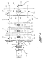
- FIG. 1 is a schematic illustration of a partially automated vehicular mechanical transmission system advantageously utilizing the present invention.
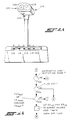
- FIG. 2 is a schematic illustration of a partially automatic shift implementation system for a mechanical transmission system advantageously utilizing the present invention.
- FIG. 2A is an elevational view of an alternate driver control for the automated transmission system of FIG. 2 .
- FIG. 3 is a schematic illustration of typical shift profiles for a heavy duty vehicular automated mechanical transmission.
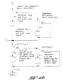
- FIGS. 4A and 4B are schematic illustrations, in flowchart format, of the present invention.
- compound transmission is used to designate a change speed or change gear transmission having a multiple forward speed main transmission section and a multiple speed auxiliary transmission section connected in series whereby the selected gear reduction in the main transmission section may be compounded by further selected gear reduction in the auxiliary transmission section.
- Synchronized clutch assembly shall designate a clutch assembly utilized to non-rotatably couple a selected gear to a shaft by means of a positive clutch in which attempted engagement of said clutch is prevented until the members of the clutch are at substantially synchronous rotation in a relatively large capacity friction means are utilized with the clutch members and are sufficient, upon initiation of a clutch engagement, to cause the clutch members and all members rotating therewith to rotate at substantially synchronous speed.
- upshift shall mean the shifting from a lower speed gear ratio into a higher speed gear ratio.
- downshift shall mean the shifting from a higher speed gear ratio to a lower speed gear ratio.
- low speed gear shall all designate the gear ratio utilized for lowest forward speed operation in a transmission or transmission section, i.e., that set of gears having the highest ratio of reduction relative to the input shaft of the transmission.
- automated shift initiation is intended to apply to initiation of fully automatic shifts as seen in above-mentioned U.S. Patent Nos. 4,361,060 and 5,109,721, to initiation of fully automatic shifts in only selected groupings of ratios as seen in above-mentioned U.S. Patent No. 4,722,248 and to automatic preselection of a shift and/or issuing of a shift prompt as seen in above-mentioned U.S. Patent Nos. 5,053,961 and 5,053,962.
- Compound transmission 10 comprises a multiple speed main transmission section 12 connected in series with a range type auxiliary section 14.
- Transmission 10 is housed within a housing H and includes an input shaft 16 driven by a prime mover such as diesel engine E through a selectively disengaged, normally engaged friction master clutch C having an input or driving portion 18 drivingly connected to the engine crankshaft 20 and a driven portion 22 rotatably fixed to the transmission input shaft 16.
- a prime mover such as diesel engine E
- a selectively disengaged, normally engaged friction master clutch C having an input or driving portion 18 drivingly connected to the engine crankshaft 20 and a driven portion 22 rotatably fixed to the transmission input shaft 16.
- the engine E is fuel throttle controlled by a manually or automatically controlled throttle device (not shown) and the master clutch C is manually controlled by a clutch pedal (not shown) or automatically controlled by a clutch actuator, or the like.
- An input shaft brake B usually operated by overtravel of the clutch pedal, is preferably provided to provide quicker upshifting as is well known in the prior art.
- a sensor 11 may be provided for sensing the rotational speed of the engine and providing a signal indicative thereof.
- the input shaft 16 carries an input gear 24 for simultaneously driving a plurality of substantially identical countershaft assemblies 26 and 26A at substantially identical rotational speeds.
- the two substantially identical countershaft assemblies are provided on diametrically opposite sides of mainshaft 28 which is generally coaxially aligned with the input shaft 16.
- Each of the countershaft assemblies comprises a countershaft 30 supported by bearings 32 and 34 in housing H, only a portion of which is schematically illustrated.
- Each of the countershafts is provided with an identical grouping of countershaft gears 38, 40, 42, 44, 46 and 48, fixed for rotation therewith.
- a plurality of mainshaft gears 50, 52, 54, 56 and 58 surround the mainshaft 28 and are selectively clutchable, one at a time, to the mainshaft 28 for rotation therewith by sliding clutch collars 60, 62 and 64 as is well known in the prior art.
- Clutch collar 60 may also be utilized to clutch input gear 24 to mainshaft 28 to provide a direct drive relationship between input shaft 16 and mainshaft 28.
- clutch collars 60, 62 and 64 are axially positioned by means of shift forks associated with the shift housing assembly 70, as well known in the prior art.
- Clutch collars 60, 62 and 64 may be of the well known acting nonsynchronized double acting jaw clutch type.
- Shift housing or actuator 70 may be actuated by electric motors or by compressed fluid, such as compressed air, and is of the type automatically controllable by a control unit as may be seen by reference to U.S. Patent Nos. 4,445,393; 4,555,959; 4,361,060; 4,676,115; 4,873,881 and 4,899,607.
- Mainshaft gear 58 is the reverse gear and is in continuous meshing engagement with countershaft gears 48 by means of conventional intermediate idler gears (not shown). It should also be noted that while main transmission section 12 does provide five selectable forward speed ratios, the lowest forward speed ratio, namely that provided by drivingly connecting mainshaft drive gear 56 to mainshaft 28, is often of such a high gear reduction it has to be considered a low or "creeper" gear which is utilized only for starting of a vehicle under severe conditions and is not usually utilized in the high transmission range. Accordingly, while main transmission section 12 does provide five forward speeds, it is usually referred to as a "four plus one" main section as only four of the forward speeds are compounded by the auxiliary range transmission section 14 utilized therewith. Similar transmissions provide 10, 13, 16 or 18 forward speeds as may be seen by reference to U.S. Patent Nos. 4,754,665 and 4,974,468.
- Jaw clutches 60, 62, and 64 are three-position clutches in that they may be positioned in the centered, nonengaged position as illustrated, or in a fully rightwardly engaged or fully leftwardly engaged position by means of actuator 70. As is well known, only one of the clutches 60, 62 and 64 is engageable at a given time and main section interlock means (not shown) are provided to lock the other clutches in the neutral condition.
- Auxiliary transmission range section 14 includes two substantially identical auxiliary countershaft assemblies 74 and 74A, each comprising an auxiliary countershaft 76 supported by bearings 78 and 80 in housing H and carrying two auxiliary section countershaft gears 82 and 84 for rotation therewith.
- Auxiliary countershaft gears 82 are constantly meshed with and support range/output gear 86 while auxiliary section countershaft gears 84 are constantly meshed with output gear 88 which is fixed to transmission output shaft 90.
- a two-position synchronized jaw clutch assembly 92 which is axially positioned by means of a shift fork (not shown) and the range section shifting actuator assembly 96, is provided for clutching either gear 86 to mainshaft 28 for low range operation or gear 88 to mainshaft 28 for direct or high range operation of the compound transmission 10.
- Range section actuator 96 may be of the type illustrated in U.S. Patent Nos. 3,648,546; 4,440,037 and 4,614,126.
- range type auxiliary section 14 is illustrated as a two-speed section utilizing spur or helical type gearing, it is understood that the present invention is also applicable to simple transmissions and to range type transmissions utilizing combined splitter/range type auxiliary sections, having three or more selectable range ratios and/or utilizing planetary type gearing. Also, any one or more of clutches 60, 62 or 64 may be of the synchronized jaw clutch type and transmission sections 12 and/or 14 may be of the single countershift type. Further, the present invention is also applicable to automated transmissions utilizing friction clutches rather than jaw clutches to engage selected ratios.
- Control system 104 for a mechanical transmission system of the present invention is schematically illustrated in Figure 2.
- Control system 104 in addition to the mechanical transmission system 10 described above, includes an electronic control unit 106, preferably microprocessor based, for receiving input signals from the engine speed sensor 11, input shaft speed sensor 98, from the output shaft speed sensor 100 (or, alternatively, the mainshaft speed sensor 102) and from the driver control console 108.
- the ECU 106 may also receive inputs from an auxiliary section position sensor 110.
- the ECU is effective to process the inputs in accordance with predetermined logic rules to issue issue command output signals to a transmission operator, such as solenoid manifold 112 which controls the mainsection section actuator 70 and the auxiliary section actuator 96, and to the driver control console 108.
- a transmission operator such as solenoid manifold 112 which controls the mainsection section actuator 70 and the auxiliary section actuator 96, and to the driver control console 108.
- ECU's of this type are well known in the prior art as may be seen by reference to U.S. Patent 4,595,986.
- the driver control and display console allows the operator to select a manual or hold mode of operation for manually selecting a shift in a given direction (i.e. upshifts or downshifts) or to neutral from the currently engaged ratio, or to select a semi-automatic preselect mode of operation, and provides a display for informing the operator of the current mode of operation (automatic or manual preselection of shifting), the current transmission operation condition (forward, reverse or neutral) and of any ratio change or shift (upshift, downshift or shift to neutral) which has been preselected but not yet implemented.
- Console 108 includes three indicator lights 114, 116 and 118 which will be lit to indicate that the transmission 10 is in a forward drive, neutral or reverse drive, respectively, condition.
- the console also includes three selectively lighted pushbuttons 120, 122, and 124 which allow the operator to select an upshift, automatic preselection mode or a downshift, respectively.
- a pushbutton 126 allows selection of a shift into neutral.
- buttons 120, 122, 124 or 126 may be cancelled (prior to execution in the case of buttons 120, 124 and 126) by redepressing the buttons.
- multiple depressions of buttons 120 and 124 may be used as commands for skip shifts.
- the buttons and lighted buttons can be replaced by other selection means, such as a toggle switch and/or a toggle switch and light or other indicia member.
- a separate button or switch for selection of reverse may be provided or reverse may be selected as a downshift from neutral. Also, neutral may be selected as an upshift from reverse or as a downshift from low.
- buttons 120 or button 124 are buttons 120 or button 124 as appropriate.
- the selected button will then be lighted until the selected shift is implemented or until the selection is cancelled.
- a mode selector 210 is utilized to select reverse (R) 212, neutral (N) 214, drive (automatic) (D) 216, hold (manual) (H) 218 and low (L) 220.
- the mode selector includes a handle 222 having a reverse interlock release button 224 and upshift 226 and downshift 228 selection buttons.
- the function of mode selector 210 is substantially identical to console 108 described above.
- the manifold 112 is preselected to cause actuator 70 to be biased to shift main transmission section 12 into neutral. This is accomplished by the operator causing a torque break or reversal by manually momentarily decreasing and/or increasing the supply of fuel to the engine and/or manually disengaging the master clutch C. As the transmission is shifted into neutral, and neutral is verified by the ECU (neutral sensed for a period of time such as 1.5 seconds), the neutral condition indicia button 116 is lighted. If the selected shift is a compound shift, i.e.
- the ECU will issue issue command output signals to manifold 112 to cause the auxiliary section actuator 96 to complete the range shift after neutral is sensed in the front box.
- the ECU When the range auxiliary section is engaged in the proper ratio, the ECU will calculate or otherwise determine, and continue to update, an enabling range or band of input shaft speeds, based upon sensed output shaft (vehicle) speed and the ratio to be engaged, which will result in an acceptably synchronous engagement of the ratio to be engaged.
- the ECU 106 will issue issue command output signals to manifold 112 to cause actuator 70 to engage the mainsection ratio to be engaged.
- the actuator will respond very quickly not requiring the operator to maintain the input shaft speed within the acceptable range for an extended period of time.
- selection button 126 is pushed. Indicating light 116 will flash until the ECU confirms that neutral is obtained at which time the light 116 will assume a continuously lighted condition while the transmission remains in neutral.
- the issuing of command output signals for engagement of a target gear is dependent upon the transmission (i.e. the input shaft) being manually brought to within an acceptable synchronous point.
- the error bands are selected to give the best shift quality for each gear ratio. These error bands are usually stored in software in the form of tables that are indexed as a function of target gear.
- U.S. Patent No. 5,063,511 provided a missed shift recovery algorithm that will access a second set of tables a short time after neutral has been sensed (one second). In a normal shift, one second is ample time for the driver to have brought the transmission to the synchronous point. If the neutral state has existed for more than the allowed time the algorithms will assume the driver has missed the shift and call for the new set of tables. This second set of tables will open the error bands to allow for a harsher shift which enhances the probability that the driver's efforts will result in engagement of the target gear instead of remaining in a neutral state.
- the ECU In the automatic preselection mode of operation, selected by use of lighted pushbutton 122, or by moving selector 210 to the "D" position, the ECU will, based upon stored logic rules, currently engaged ratio (which may be position sensed and/or calculated by comparing input shaft to output shaft speed) and output shaft speed, determine if an upshift or a downshift is required and preselect same.
- the operator is informed that an upshift or downshift is preselected and will be semi-automatically implemented by a command output signal from ECU 106 causing either lighted pushbutton 120 or lighted pushbutton 124 to flash and/or an audible shift alert signal.
- the operator may initiate semi-automatic implementation of the automatically preselected shift as indicated above or may cancel the automatic mode by depression of pushbutton 122.
- the minimum value (ES MIN ) is usually about the stall speed of the engine while the maximum value (ES MAX ) is slightly below a destructive speed.
- the minimum speed is usually about 600 RPM
- the maximum speed is about 2200 RPM
- the desirable range is about 1300-1600 RPM.
- shifts are automatically initiated, in this transmission system embodiment preselected, in accordance with shift profiles as is well known in the prior art.
- Typical shift profiles are schematically illustrated in Figure 3 and are usually determined in the ECU 106 by calculation and/or look-up table methods.
- lines 240 and 242 represent typical default values for upshift and downshift, respectively, shift profiles. Operation in area 244 between the upshift and downshift profiles requires no action, operation in area 246 to the right of upshift profiles 240 requires initiation of an upshift and operation in area 248 to the left of downshift profile 242 requires initiation of a downshift.
- the upshift profile may be temporarily offset to the right after a downshift and/or the downshift profile may be temporarily offset to left after an upshift.
- Lines 250 and 252, respectively, represent the anti-hunt offset upshift and downshift, respectively, profiles.
- the offsets 254 may be by 150 or more RPM.
- the shift profiles will return to the default values from the offset values thereof upon the passage of time and/or upon obtaining a certain vehicle or engine speed.
- the control of the present invention allows the vehicle operator or driver to manually modify vehicle performance, while operating in the automatic or drive mode of transmission system 10 by manually causing the engine speeds at which shifts are automatically initiated to be increased or decreased, within limits.
- off-set profile 252 represents the minimum downshift engine speeds (ES MIN DS ) and off-set profile 250 represents the maximum upshift engine speeds (ES MAX US ), lines 256 and 258, respectively, will represent the minimum upshift engine speeds (ES MIN US ) and maximum downshift engine speeds (ES MAX DS ) of partially automated mechanical transmission 10.
- the vehicle driver may use the upshift and downshift buttons 226 and 228 to adjust vehicle performance.
- Manual operation of the upshift button 226 while in the drive mode will signal a selection of advanced upshifts, and delayed downshifts, causing the ECU to temporarily decrease the engine speeds (ES US and ES DS ) at which upshifts and downshifts will be automatically initiated.
- this can result in moving from shift profiles 240 and/or 242 to shift profiles 256 and/or 252 and/or from shift profiles 250 and/or 258 to shift profiles 240 and/or 258 to shift profiles 240 and/or 242.
- the manually selected shift profile offsets be only temporary and that, after the occurrence of defined preconditions, such as the passage of time, the completion of a shift and/or engine or vehicle speed obtained a reference value, the shift point engine speeds return to the default value (240/242) thereof.
- the present invention allows the operator of a vehicle equipped with an automated transmission and operating in an automatic shift initiation mode to temporarily advance or delay automatic shift initiation to modify vehicle performance for then existing conditions. For example, if a vehicle driver sees a steep grade ahead, he may push the "downshift" button 228 to delay automatic upshifts and/or advance automatic downshifts.
Landscapes
- Engineering & Computer Science (AREA)
- General Engineering & Computer Science (AREA)
- Mechanical Engineering (AREA)
- Control Of Transmission Device (AREA)
- Arrangement Or Mounting Of Control Devices For Change-Speed Gearing (AREA)
- Radar Systems Or Details Thereof (AREA)
- Measuring Pulse, Heart Rate, Blood Pressure Or Blood Flow (AREA)
- Control Of Vehicle Engines Or Engines For Specific Uses (AREA)
- Control Of Driving Devices And Active Controlling Of Vehicle (AREA)
Claims (8)
- Automatisches Fahrzeugetriebesystem mit einem durch Kraftstoff- oder Gemischdrosselung gesteuerten Motor (E), mit einem mehrgängigen mechanischen Gangwechselgetriebe (10), das eine Eingangswelle (16) und eine Ausgangswelle (90) aufweist, mit einer Reibungskupplung die kraftübertragend zwischen dem Motor und der Getriebeeingangswelle angeordnet ist, mit einem ersten Sensor (11/98/100) der ein erstens die Motordrehzahl (ES/IS/OS*GR) kennzeichnendes Eingangssignal liefert, mit einem Betriebsartenwähler (210) zur manuellen Wahl von Getriebebetriebsarten, zu denen eine Betriebsart (H) mit manueller Auslösung von Schaltvorgängen und eine Betriebsart (D) mit automatischer Auslösung von Schaltvorgängen gehören, der ein zweites die ausgewählte Getriebsbetriebsart kennzeichnendes Eingangssignal liefert, mit einem Hochschalt/Zurückschalt- Wähler (226/228) zur Auswahl der manuellen Auslösung von Hochschalt- bzw. Zurückschaltvorgängen in der Betriebsart mit manueller Schaltauslösung, und zum Liefern von dritten bzw. vierten Eingangssignalen, die die Richtung des manuell ausgewählten Schaltvorgangs kennzeichnen, mit einer zentralen Verarbeitungseinheit (106), die die Eingangssignale empfängt und dieselben gemäß vorbestimmter logischer Regeln verarbeitet, um Befehlsausgangssignale zu erzeugen, und mit Aktuatoren (112,70,96), die auf die Ausgangssignale reagieren, um das Schalten des Getriebes zu kontrollieren,
wobei das System in der Betriebsart mit automatischer Schaltauslösung automatisch Hochschaltvorgänge auslöst, wenn erfasst wird, dass die Motordrehzahl (ESS) größer ist als ein Motordrehzahl-Hochschaltwert (ESUS), und das automatisch Zurückschaltvorgänge auslöst, wenn die erfaßte Motordrehzahl geringer ist als ein Motordrehzahl-Zurückschaltwert (ESDS) wobei die Hochschalt- und Zurückschalt-Motordrehzahlwerte maximale (ESMAX US, ESMAX DS) und minimale (ESMIN US und ESMIN DS) Werte beinhalten,
wobei das System gekennzeichnet ist durch:
Mittel, die in der Betriebsart mit automatischer Schaltauslösung auf eine manuelle Wahl einer Hochschaltauslösung so reagieren, dass der jeweilige Wert des Motordrehzahlhochschalt- und des Motordrehzahlzurückschaltwertes vermindert, jedoch nicht unter die Minimalwerte (ES MIN US und ES MIN DS) vermindert wird, und die auf eine Manuelle Auswahl eines Zurückschaltauslösens reagieren, indem die Werte der Motordrehzahlhochschalt- und Zurückschaltwerte erhöht, jedoch nicht über die Maximalwerte (ES MAX US und ES MAX DS) erhöht werden. - System nach Anspruch 1, bei dem die Motordrehzahlwerte um ungefähr 150 U/Min erhöht werden.
- System nach Anspruch 1, bei dem die Motordrehzahlwerte um ungefähr 150 U/Min vermindert werden.
- System nach Anspruch 1, bei dem die Steuerung bewirkt, dass ein Motordrehzahl-Standarthochschaltwert (240) zwischen deren Maximal- und Minimalwert gebildet wird und dass das System den Motordrehzahlhochschaltwert von dem Standardwert auf den Maximalwert und von dem Minimalwert auf den Standardwert erhöht.
- System nach Anspruch 4, bei dem das System den Motordrehzahl-Hochschaltstandartwert von dem Standardwert auf den Minimalwert und von dem Maximalwert auf den Standardwert vermindert.
- System nach Anspruch 4 oder 5, bei dem die Motordrehzahlwerte nach einer vorbestimmte Zeitspanne nach Empfang des dritten oder vierten Eingangssignals ihren Standardwert annehmen.
- System nach Anspruch 4 oder 5, bei dem die Motordrehzahlwerte, wenn die Motordrehzahlwerte nach dem Empfang des dritten oder vierten Eingangssignals mit einem Referenzwert übereinstimmen, ihre jeweilige Standardwert annehmen.
- System nach Anspruch 1, wobei das System in der Betriebsart mit manueller Schaltauslösung Mittel enthält, die auf (i) eine Auswahl eines Schaltvorganges aus einer gegenwärtig eingerückten Gangstufe heraus oder aus dem Leerlauf heraus in eine ausgewählte Zielgangstufe und (ii) auf die Bestätigung eines Getriebeleerlaufzustandes reagieren, um (i) die dann aktuelle Fahrzeuggeschwindigkeit als eine anfängliche Fahrzeuggeschwindigkeit VSi (ii) zu erfassen, (ii) und danach die weitgehende Synchronisierung des Getriebes zu erfassen und (iii) danach Befehlsausgangssignale an den Aktuator abzugeben, um dem Getriebe zu gestatten, in die ausgewählte Gangstufe geschaltet zu werden, wobei das Mittel den weitgehenden Synchronlauf des Getriebes erfasst, indem das erste Signal mit einem Vergleichsbereich verglichen wird, der als eine Funktion der ausgewählten Gangstufe und des zweiten Signals bestimmt wird.
Applications Claiming Priority (2)
| Application Number | Priority Date | Filing Date | Title |
|---|---|---|---|
| US126843 | 1993-09-22 | ||
| US08/126,843 US5406861A (en) | 1993-09-22 | 1993-09-22 | Manual modification of automatic mode shift points |
Publications (2)
| Publication Number | Publication Date |
|---|---|
| EP0644360A1 EP0644360A1 (de) | 1995-03-22 |
| EP0644360B1 true EP0644360B1 (de) | 1997-08-20 |
Family
ID=22426972
Family Applications (1)
| Application Number | Title | Priority Date | Filing Date |
|---|---|---|---|
| EP94306786A Expired - Lifetime EP0644360B1 (de) | 1993-09-22 | 1994-09-16 | Händische Verstellung der Schaltpunkte im Automatikbetrieb |
Country Status (10)
| Country | Link |
|---|---|
| US (1) | US5406861A (de) |
| EP (1) | EP0644360B1 (de) |
| JP (1) | JPH07167289A (de) |
| KR (1) | KR100299016B1 (de) |
| AT (1) | ATE157151T1 (de) |
| AU (1) | AU672524B2 (de) |
| BR (1) | BR9403613A (de) |
| CA (1) | CA2132562C (de) |
| DE (1) | DE69405066T2 (de) |
| ES (1) | ES2107754T3 (de) |
Cited By (1)
| Publication number | Priority date | Publication date | Assignee | Title |
|---|---|---|---|---|
| DE102006050325B4 (de) * | 2005-10-31 | 2017-06-01 | Honda Motor Co., Ltd. | Schaltsteuervorrichtung für ein Automatikgetriebe |
Families Citing this family (30)
| Publication number | Priority date | Publication date | Assignee | Title |
|---|---|---|---|---|
| GB9525055D0 (en) * | 1995-12-07 | 1996-02-07 | Eaton Corp | Controled for automated mechanical transmission system |
| US5678453A (en) * | 1996-02-01 | 1997-10-21 | Eaton Corporation | Start ratio selection for vehicular automated transmissions |
| GB9617956D0 (en) * | 1996-08-28 | 1996-10-09 | Eaton Corp | Downshift control method/system for vehicular automated mechanical transmission |
| US5846161A (en) * | 1996-12-03 | 1998-12-08 | Caterpillar Inc. | Control system for an automatic transmission having shift points based on part throttle positions which are used when engine speed is lowered below an adjustable minimum engine speed setting |
| US5809835A (en) * | 1997-01-21 | 1998-09-22 | Ford Global Technologies, Inc. | Manual transmission shift lever |
| GB9721823D0 (en) | 1997-10-16 | 1997-12-17 | Eaton Corp | Shift into optimal engine braking control system and method |
| DE19747262A1 (de) * | 1997-10-25 | 1999-05-06 | Deere & Co | Getriebesteuerung und Steuerverfahren für ein Lastschaltgetriebe |
| US6285941B1 (en) | 1998-08-31 | 2001-09-04 | Eaton Corporation | Method/system for controlling shifting in an automated mechanical transmission system |
| US6157886A (en) * | 1998-08-31 | 2000-12-05 | Eaton Corporation | Method/system for controlling upshifting in an automated mechanical transmission system |
| US6233512B1 (en) | 1998-09-08 | 2001-05-15 | Eaton Corporation | Method/system for controlling upshifting in an automated mechanical transmission system |
| US6085606A (en) * | 1998-11-03 | 2000-07-11 | Eaton Corporation | Mechanical transmission with reduced ratio steps in upper transmission ratios |
| GB9828452D0 (en) | 1998-12-24 | 1999-02-17 | Eaton Corp | Automated transmission downshift control |
| US6042507A (en) * | 1999-04-22 | 2000-03-28 | Eaton Corporation | Torque converter lockup control |
| US6178366B1 (en) | 1999-07-19 | 2001-01-23 | Eaton Corporation | Method/system for initiating automatic upshifting in an automated mechanical transmission system |
| US6480774B1 (en) | 1999-07-23 | 2002-11-12 | Eaton Corporation | Convertible transmission system |
| US6658339B1 (en) | 1999-11-26 | 2003-12-02 | Eaton Corporation | Driver-programmable driving mode system for automatic transmissions |
| JP2001213201A (ja) * | 1999-12-17 | 2001-08-07 | Getrag Getriebe & Zahnradfab Hermann Hagenmeyer Gmbh & Co | 自動車のための自動的な駆動機構列並びに駆動機構列を制御する方法 |
| DE10003140C1 (de) * | 2000-01-26 | 2001-08-09 | Daimler Chrysler Ag | Betriebsarten-Wähleinrichtung für Fahrzeuggetriebe |
| EP1355209A1 (de) | 2002-04-18 | 2003-10-22 | Ford Global Technologies, LLC | Fahrzeugsteuerungssystem |
| EP1730046B1 (de) * | 2004-03-16 | 2008-08-06 | The Dial Corporation | Auftragsvorrichtung |
| GB0502867D0 (en) * | 2005-02-11 | 2005-03-16 | Agco Sa | Transmission controllers |
| GB2446958B (en) * | 2005-02-11 | 2009-09-02 | Agco Sa | Multi ratio transmission |
| US7717823B2 (en) | 2006-11-27 | 2010-05-18 | Zf Friedrichshafen Ag | Method and apparatus for changing shift scheduling modes of automated mechanical transmission |
| JP5139520B2 (ja) * | 2007-06-08 | 2013-02-06 | ボルボ ラストバグナー アーベー | 車両における自動的に選択された変速回転数制限を調整する方法 |
| US7747372B2 (en) * | 2007-07-03 | 2010-06-29 | Toyota Motor Engineering & Manufacturing North America, Inc. | Systems and methods for user control of vehicular transmission shift points |
| US7859394B1 (en) * | 2008-01-23 | 2010-12-28 | Fes Llc | Shift light system and method |
| DE102009055833A1 (de) * | 2009-11-26 | 2011-06-01 | GM Global Technology Operations LLC, ( n. d. Ges. d. Staates Delaware ), Detroit | Verfahren zur Steuerung eines Schaltvorganges eines Automatikgetriebes |
| JP5244169B2 (ja) * | 2010-12-24 | 2013-07-24 | 富士重工業株式会社 | 車両の駆動力制御装置 |
| US9079575B2 (en) | 2012-11-14 | 2015-07-14 | Caterpillar Inc. | Machine powertrain control system and method |
| DE102014017175B4 (de) * | 2014-11-20 | 2016-11-10 | Audi Ag | Verfahren und Vorrichtung zum Betreiben eines Kraftfahrzeugs |
Citations (3)
| Publication number | Priority date | Publication date | Assignee | Title |
|---|---|---|---|---|
| EP0109759B1 (de) * | 1982-11-17 | 1987-03-18 | Eaton Corporation | Steuereinrichtung für automatische Getriebe |
| US4669335A (en) * | 1983-11-28 | 1987-06-02 | Mazda Motor Corporation | Control of a vehicle automatic transmission |
| EP0513424A1 (de) * | 1991-05-17 | 1992-11-19 | Siemens Aktiengesellschaft | Kraftfahrzeug-Getriebe mit einem Steuergerät |
Family Cites Families (17)
| Publication number | Priority date | Publication date | Assignee | Title |
|---|---|---|---|---|
| JPS598698B2 (ja) * | 1978-09-05 | 1984-02-27 | 日産自動車株式会社 | 自動変速機の変速制御装置 |
| CA1159536A (en) * | 1978-09-29 | 1983-12-27 | Alan L. Miller | Transmission control system for multi-ratio gear arrangement |
| CA1123202A (en) * | 1978-10-04 | 1982-05-11 | William H. Pullen | Machine tool for dressing the end face of an engine cylinder liner |
| GB8418749D0 (en) * | 1984-07-23 | 1984-08-30 | Eaton Ltd | Semi-automatic transmission control |
| AU577882B2 (en) * | 1984-08-10 | 1988-10-06 | Toyota Jidosha Kabushiki Kaisha | Vehicle transmission control in power and economy modes |
| AU591666B2 (en) * | 1985-03-23 | 1989-12-14 | Zahnradfabrik Friedrichshafen Ag | Control device for shifting step-by-step shift gears |
| DE3626100C2 (de) * | 1985-08-10 | 1995-12-14 | Zahnradfabrik Friedrichshafen | Steuereinrichtung zum selbsttätigen Schalten von Stufenwechselgetrieben |
| US4843551A (en) * | 1987-09-28 | 1989-06-27 | Saturn Corporation | Failure mode shift pattern alteration for an electronically controlled transmission |
| US5053961A (en) * | 1989-06-19 | 1991-10-01 | Eaton Corporation | Semi-automatic shift implementation for mechanical transmission system |
| US5053962A (en) * | 1989-06-19 | 1991-10-01 | Eaton Corporation | Automatic shift preselection mode for mechanical transmission system with semi-automatic shift implementation |
| US4991455A (en) * | 1989-12-01 | 1991-02-12 | Ford New Holland, Inc. | High speed deceleration of a power shift transmission |
| EP0471102B1 (de) * | 1990-08-14 | 1994-01-05 | Siemens Aktiengesellschaft | Getriebesteuerung für ein Kraftfahrzeug |
| US5050079A (en) * | 1990-08-17 | 1991-09-17 | Eaton Corporation | Mode control for mechanical transmission system with semi-automatic shift implementation and manual and automatic shift preselection modes |
| US5315514A (en) * | 1990-08-17 | 1994-05-24 | Eaton Corporation | Unexpected N logic for vehicular semi-automated mechanical transmissions |
| US5109721A (en) * | 1991-05-09 | 1992-05-05 | Eaton Corporation | Range shifting only fault tolerance method/system |
| US5323669A (en) * | 1992-10-29 | 1994-06-28 | Eaton Corporation | Fault tolerant method of transmission gear selection |
| US5261288A (en) * | 1992-12-18 | 1993-11-16 | Eaton Corporation | Enhanced missed shift from neutral recovery for automated or semi-automated mechanical transmission system |
-
1993
- 1993-09-22 US US08/126,843 patent/US5406861A/en not_active Expired - Lifetime
-
1994
- 1994-09-16 AT AT94306786T patent/ATE157151T1/de not_active IP Right Cessation
- 1994-09-16 ES ES94306786T patent/ES2107754T3/es not_active Expired - Lifetime
- 1994-09-16 EP EP94306786A patent/EP0644360B1/de not_active Expired - Lifetime
- 1994-09-16 DE DE69405066T patent/DE69405066T2/de not_active Expired - Fee Related
- 1994-09-20 AU AU73097/94A patent/AU672524B2/en not_active Ceased
- 1994-09-21 CA CA002132562A patent/CA2132562C/en not_active Expired - Fee Related
- 1994-09-22 JP JP6254321A patent/JPH07167289A/ja active Pending
- 1994-09-22 BR BR9403613A patent/BR9403613A/pt not_active IP Right Cessation
- 1994-09-22 KR KR1019940023891A patent/KR100299016B1/ko not_active Expired - Fee Related
Patent Citations (3)
| Publication number | Priority date | Publication date | Assignee | Title |
|---|---|---|---|---|
| EP0109759B1 (de) * | 1982-11-17 | 1987-03-18 | Eaton Corporation | Steuereinrichtung für automatische Getriebe |
| US4669335A (en) * | 1983-11-28 | 1987-06-02 | Mazda Motor Corporation | Control of a vehicle automatic transmission |
| EP0513424A1 (de) * | 1991-05-17 | 1992-11-19 | Siemens Aktiengesellschaft | Kraftfahrzeug-Getriebe mit einem Steuergerät |
Cited By (1)
| Publication number | Priority date | Publication date | Assignee | Title |
|---|---|---|---|---|
| DE102006050325B4 (de) * | 2005-10-31 | 2017-06-01 | Honda Motor Co., Ltd. | Schaltsteuervorrichtung für ein Automatikgetriebe |
Also Published As
| Publication number | Publication date |
|---|---|
| AU672524B2 (en) | 1996-10-03 |
| ES2107754T3 (es) | 1997-12-01 |
| JPH07167289A (ja) | 1995-07-04 |
| US5406861A (en) | 1995-04-18 |
| ATE157151T1 (de) | 1997-09-15 |
| KR950009029A (ko) | 1995-04-21 |
| CA2132562A1 (en) | 1995-03-23 |
| DE69405066D1 (de) | 1997-09-25 |
| DE69405066T2 (de) | 1998-03-19 |
| AU7309794A (en) | 1995-04-06 |
| CA2132562C (en) | 2000-09-19 |
| BR9403613A (pt) | 1995-05-23 |
| KR100299016B1 (ko) | 2001-12-01 |
| EP0644360A1 (de) | 1995-03-22 |
Similar Documents
| Publication | Publication Date | Title |
|---|---|---|
| EP0644360B1 (de) | Händische Verstellung der Schaltpunkte im Automatikbetrieb | |
| EP0404353B1 (de) | Halbautomatische Schaltdurchführung eines mechanischen Getriebesystems | |
| CA2049242C (en) | Mode control for mechanical transmission system with semi-automatic shift implementation and manual and automatic shift preselection modes | |
| EP0651181B1 (de) | Drehmomentermittlung in einem Antriebsstrang | |
| EP0404387B1 (de) | Automatische Schaltvorwahl für ein mechanisches Getriebesystem mit halbautomatischer Schaltung | |
| EP0404354B1 (de) | Steuersystem und Methode zur Erfassung und Signalisierung der Leerlaufstellung in einem halbautomatischen Getriebe | |
| EP0449499B1 (de) | Anfahr-Steuerungsverfahren | |
| EP0651180B1 (de) | Wiederherstellung des Betriebszustandes eines Bereichsgetriebes nach einer Getriebestrangunterbrechung | |
| CA2049239C (en) | Unexpected n logic | |
| CA2020109C (en) | Shift implementation control system and method for mechanical transmission system | |
| EP0413412B1 (de) | Halbautomatisches Schaltdurchführungs-Steuerungssystem | |
| EP0602849B1 (de) | Verfahren zur Fehlerbeseitigung bei erfolglosen Schaltversuchen aus dem Leerlauf in automatischen oder halbautomatischen mechanischen Getriebesystemen | |
| US5429559A (en) | Forced engagement logic | |
| EP0576156B1 (de) | Verbessertes mechanisches semi-automatisches Getriebesystem | |
| EP0565257A1 (de) | Mechanisches semi-automatisches Getriebesystem |
Legal Events
| Date | Code | Title | Description |
|---|---|---|---|
| PUAI | Public reference made under article 153(3) epc to a published international application that has entered the european phase |
Free format text: ORIGINAL CODE: 0009012 |
|
| AK | Designated contracting states |
Kind code of ref document: A1 Designated state(s): AT DE ES FR GB IT NL SE |
|
| 17P | Request for examination filed |
Effective date: 19950518 |
|
| 17Q | First examination report despatched |
Effective date: 19960207 |
|
| GRAG | Despatch of communication of intention to grant |
Free format text: ORIGINAL CODE: EPIDOS AGRA |
|
| GRAH | Despatch of communication of intention to grant a patent |
Free format text: ORIGINAL CODE: EPIDOS IGRA |
|
| GRAH | Despatch of communication of intention to grant a patent |
Free format text: ORIGINAL CODE: EPIDOS IGRA |
|
| GRAA | (expected) grant |
Free format text: ORIGINAL CODE: 0009210 |
|
| AK | Designated contracting states |
Kind code of ref document: B1 Designated state(s): AT DE ES FR GB IT NL SE |
|
| REF | Corresponds to: |
Ref document number: 157151 Country of ref document: AT Date of ref document: 19970915 Kind code of ref document: T |
|
| REF | Corresponds to: |
Ref document number: 69405066 Country of ref document: DE Date of ref document: 19970925 |
|
| ET | Fr: translation filed | ||
| ITF | It: translation for a ep patent filed | ||
| REG | Reference to a national code |
Ref country code: ES Ref legal event code: FG2A Ref document number: 2107754 Country of ref document: ES Kind code of ref document: T3 |
|
| PLBE | No opposition filed within time limit |
Free format text: ORIGINAL CODE: 0009261 |
|
| STAA | Information on the status of an ep patent application or granted ep patent |
Free format text: STATUS: NO OPPOSITION FILED WITHIN TIME LIMIT |
|
| 26N | No opposition filed | ||
| REG | Reference to a national code |
Ref country code: GB Ref legal event code: IF02 |
|
| PGFP | Annual fee paid to national office [announced via postgrant information from national office to epo] |
Ref country code: AT Payment date: 20050701 Year of fee payment: 12 |
|
| PGFP | Annual fee paid to national office [announced via postgrant information from national office to epo] |
Ref country code: NL Payment date: 20050808 Year of fee payment: 12 |
|
| PGFP | Annual fee paid to national office [announced via postgrant information from national office to epo] |
Ref country code: FR Payment date: 20050902 Year of fee payment: 12 |
|
| PGFP | Annual fee paid to national office [announced via postgrant information from national office to epo] |
Ref country code: ES Payment date: 20050919 Year of fee payment: 12 |
|
| PG25 | Lapsed in a contracting state [announced via postgrant information from national office to epo] |
Ref country code: AT Free format text: LAPSE BECAUSE OF NON-PAYMENT OF DUE FEES Effective date: 20060916 |
|
| PGFP | Annual fee paid to national office [announced via postgrant information from national office to epo] |
Ref country code: IT Payment date: 20060930 Year of fee payment: 13 |
|
| PG25 | Lapsed in a contracting state [announced via postgrant information from national office to epo] |
Ref country code: NL Free format text: LAPSE BECAUSE OF NON-PAYMENT OF DUE FEES Effective date: 20070401 |
|
| NLV4 | Nl: lapsed or anulled due to non-payment of the annual fee |
Effective date: 20070401 |
|
| REG | Reference to a national code |
Ref country code: FR Ref legal event code: ST Effective date: 20070531 |
|
| REG | Reference to a national code |
Ref country code: ES Ref legal event code: FD2A Effective date: 20060918 |
|
| PG25 | Lapsed in a contracting state [announced via postgrant information from national office to epo] |
Ref country code: ES Free format text: LAPSE BECAUSE OF NON-PAYMENT OF DUE FEES Effective date: 20060918 |
|
| PG25 | Lapsed in a contracting state [announced via postgrant information from national office to epo] |
Ref country code: FR Free format text: LAPSE BECAUSE OF NON-PAYMENT OF DUE FEES Effective date: 20061002 |
|
| PGFP | Annual fee paid to national office [announced via postgrant information from national office to epo] |
Ref country code: GB Payment date: 20080808 Year of fee payment: 15 |
|
| PGFP | Annual fee paid to national office [announced via postgrant information from national office to epo] |
Ref country code: DE Payment date: 20080930 Year of fee payment: 15 |
|
| PGFP | Annual fee paid to national office [announced via postgrant information from national office to epo] |
Ref country code: SE Payment date: 20080905 Year of fee payment: 15 |
|
| PG25 | Lapsed in a contracting state [announced via postgrant information from national office to epo] |
Ref country code: IT Free format text: LAPSE BECAUSE OF NON-PAYMENT OF DUE FEES Effective date: 20070916 |
|
| EUG | Se: european patent has lapsed | ||
| GBPC | Gb: european patent ceased through non-payment of renewal fee |
Effective date: 20090916 |
|
| PG25 | Lapsed in a contracting state [announced via postgrant information from national office to epo] |
Ref country code: DE Free format text: LAPSE BECAUSE OF NON-PAYMENT OF DUE FEES Effective date: 20100401 |
|
| PG25 | Lapsed in a contracting state [announced via postgrant information from national office to epo] |
Ref country code: GB Free format text: LAPSE BECAUSE OF NON-PAYMENT OF DUE FEES Effective date: 20090916 |
|
| PG25 | Lapsed in a contracting state [announced via postgrant information from national office to epo] |
Ref country code: SE Free format text: LAPSE BECAUSE OF NON-PAYMENT OF DUE FEES Effective date: 20090917 |