EP0644508A1 - Méthode sûre d'identification optique et moyens associés - Google Patents
Méthode sûre d'identification optique et moyens associés Download PDFInfo
- Publication number
- EP0644508A1 EP0644508A1 EP94306458A EP94306458A EP0644508A1 EP 0644508 A1 EP0644508 A1 EP 0644508A1 EP 94306458 A EP94306458 A EP 94306458A EP 94306458 A EP94306458 A EP 94306458A EP 0644508 A1 EP0644508 A1 EP 0644508A1
- Authority
- EP
- European Patent Office
- Prior art keywords
- diffraction grating
- article
- strip
- pattern
- secure identification
- Prior art date
- Legal status (The legal status is an assumption and is not a legal conclusion. Google has not performed a legal analysis and makes no representation as to the accuracy of the status listed.)
- Granted
Links
Images


Classifications
-
- G—PHYSICS
- G06—COMPUTING OR CALCULATING; COUNTING
- G06K—GRAPHICAL DATA READING; PRESENTATION OF DATA; RECORD CARRIERS; HANDLING RECORD CARRIERS
- G06K7/00—Methods or arrangements for sensing record carriers, e.g. for reading patterns
- G06K7/10—Methods or arrangements for sensing record carriers, e.g. for reading patterns by electromagnetic radiation, e.g. optical sensing; by corpuscular radiation
- G06K7/10544—Methods or arrangements for sensing record carriers, e.g. for reading patterns by electromagnetic radiation, e.g. optical sensing; by corpuscular radiation by scanning of the records by radiation in the optical part of the electromagnetic spectrum
- G06K7/10821—Methods or arrangements for sensing record carriers, e.g. for reading patterns by electromagnetic radiation, e.g. optical sensing; by corpuscular radiation by scanning of the records by radiation in the optical part of the electromagnetic spectrum further details of bar or optical code scanning devices
- G06K7/10831—Arrangement of optical elements, e.g. lenses, mirrors, prisms
-
- G—PHYSICS
- G06—COMPUTING OR CALCULATING; COUNTING
- G06K—GRAPHICAL DATA READING; PRESENTATION OF DATA; RECORD CARRIERS; HANDLING RECORD CARRIERS
- G06K19/00—Record carriers for use with machines and with at least a part designed to carry digital markings
- G06K19/06—Record carriers for use with machines and with at least a part designed to carry digital markings characterised by the kind of the digital marking, e.g. shape, nature, code
- G06K19/06009—Record carriers for use with machines and with at least a part designed to carry digital markings characterised by the kind of the digital marking, e.g. shape, nature, code with optically detectable marking
- G06K19/06046—Constructional details
-
- G—PHYSICS
- G06—COMPUTING OR CALCULATING; COUNTING
- G06K—GRAPHICAL DATA READING; PRESENTATION OF DATA; RECORD CARRIERS; HANDLING RECORD CARRIERS
- G06K19/00—Record carriers for use with machines and with at least a part designed to carry digital markings
- G06K19/06—Record carriers for use with machines and with at least a part designed to carry digital markings characterised by the kind of the digital marking, e.g. shape, nature, code
- G06K19/08—Record carriers for use with machines and with at least a part designed to carry digital markings characterised by the kind of the digital marking, e.g. shape, nature, code using markings of different kinds or more than one marking of the same kind in the same record carrier, e.g. one marking being sensed by optical and the other by magnetic means
- G06K19/10—Record carriers for use with machines and with at least a part designed to carry digital markings characterised by the kind of the digital marking, e.g. shape, nature, code using markings of different kinds or more than one marking of the same kind in the same record carrier, e.g. one marking being sensed by optical and the other by magnetic means at least one kind of marking being used for authentication, e.g. of credit or identity cards
- G06K19/16—Record carriers for use with machines and with at least a part designed to carry digital markings characterised by the kind of the digital marking, e.g. shape, nature, code using markings of different kinds or more than one marking of the same kind in the same record carrier, e.g. one marking being sensed by optical and the other by magnetic means at least one kind of marking being used for authentication, e.g. of credit or identity cards the marking being a hologram or diffraction grating
-
- G—PHYSICS
- G06—COMPUTING OR CALCULATING; COUNTING
- G06K—GRAPHICAL DATA READING; PRESENTATION OF DATA; RECORD CARRIERS; HANDLING RECORD CARRIERS
- G06K7/00—Methods or arrangements for sensing record carriers, e.g. for reading patterns
- G06K7/10—Methods or arrangements for sensing record carriers, e.g. for reading patterns by electromagnetic radiation, e.g. optical sensing; by corpuscular radiation
- G06K7/10544—Methods or arrangements for sensing record carriers, e.g. for reading patterns by electromagnetic radiation, e.g. optical sensing; by corpuscular radiation by scanning of the records by radiation in the optical part of the electromagnetic spectrum
- G06K7/10712—Fixed beam scanning
- G06K7/10762—Relative movement
- G06K7/10782—Slot readers
Definitions
- the present invention relates to secure identification generally and, more particularly, but not by way of limitation, to unique identification method and means that that employ a compound diffraction grating strip.
- Identification has become increasingly more important in a variety of settings. For example, employee identification cards may be used to gain access to security areas of a facility and/or in time and attendance reporting. Drivers' licenses are often used to verify the identification of the possessors thereof.
- Various types of credit and debit cards are employed to make purchases, obtain cash or traveler's checks, and/or to transfer funds, for example. In all of these settings, forgery and copying of such identification means result in the compromising of secret information and the loss of hundreds of millions of dollars worth of merchandise and cash annually.
- credit card type identification is verified at the point of sale; however, as the need for more unattended credit card use expands, there is a greater need to verify the authenticity of the credit card to which the transaction is being charged.
- One of the major methods used by forgers of credit cards is to obtain the numbers encoded on a valid credit card during a legitimate transaction and, at a later time, to include this number on another credit card.
- the charge is applied to the valid number and the account of the owner of the valid credit card is charged accordingly.
- the only way to prevent this type of theft is to computer validate each transaction as the purchase is taking place and to have a cashier check the identification of the person purchasing the items against the name returned by the validation computer.
- identification means There have been a number of attempts to create secure identification means involving optical and/or magnetic information recorded on identification means.
- none of such known identification means provides a high level of protection against forgery and/or copying.
- many such identification means do not provide a high degree of assurance that duplicate identification means will not be issued to two or more users.
- a method of providing secure identification for an article comprising: providing on said article a diffraction grating strip comprising a pattern of a series of diffraction grating elements, each said diffraction grating element to diffract light, from a light source, in one of at least three selected different planes; serially illuminating said diffraction grating elements, detecting changes in plane of diffracted light as said diffraction grating elements are serially illuminated, and generating first information representative of said changes in plane; storing said first information representative of said changes in plane; subsequently, serially illuminating said diffraction grating elements, detecting changes in plane of diffracted light as said diffraction grating elements are serially illuminated, and generating second information representative of said changes in plane; and then, comparing said first and second information to determine the authenticity or not of said article.
- a coded pattern is placed on said diffraction grating strip, with one of said coded pattern and said pattern of diffraction grating elements precessing with respect to the other and the coded pattern is read, stored, and compared as part of said first and second information, as above.
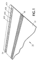
- Figure 1 is an enlarged, fragmentary, perspective view of an identification card with a secure optical identification illustrating one aspect of the present invention.
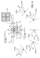
- Figure 2 is an enlarged, fragmentary, perspective, schematic view of an apparatus for reading the optical identification of Figure 1.
- Figures 3 and 4 are enlarged, top plan views illustrating how the apparatus of Figure 2 reads the optical identification of Figure 1.
- Figure 5 is a top plan view indicating how an identifying number is derived for the optical identification of Figure 1.
- Figure 6 is an enlarged, fragmentary, top plan view of an alternative secure optical identification being read.
- Figure 7 is an enlarged, fragmentary, top plan view indicating how an additional identifying number is derived for the optical identification of Figure 1.
- Figure 8 is an enlarged, fragmentary, perspective view indicating how the apparatus of Figure 2 reads the additional identifying number of Figure 7.
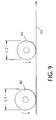
- Figure 9 is a schematic side elevational view indicating how the relative patterns of Figures 5 and 7 can be made to shift.
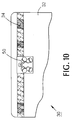
- Figure 10 is an enlarged, fragmentary, perspective view indicating a further method of providing security to the secure optical identification.
- Figure 11 is a block/schematic diagram illustrating decoding/encoding circuitry for the present invention.
- Figure 1 illustrates an identification card, generally indicated by the reference numeral 30, which may be assumed to be a bank credit card, or employee identification card, or the like.
- Card 30 includes a substrate 32 which has disposed thereon a foil strip 34 containing a plurality of diffraction grating elements.
- Substrate 32 may have disposed thereon a conventional magnetic strip 36 in which information may be magnetically encrypted.
- Magnetic strip 36 may be separate from foil strip 34, as shown on Figure 1, or it may have the foil strip superjacent it, such as is described in US Patent No. 4,631,222, issued December 23, 1986, to Sander, and titled EMBOSSING FOILS, and US Patent No. 4,684, issued August 4, 1987, to Colgate, and titled SECURITY TAPE WITH INTEGRATED HOLOGRAM AND MAGNETIC STRIP, the disclosures of which patents are incorporated by reference hereinto.
- Foil strip 34 is parallel to and spaced from the upper edge of card 30 and comprises a linear array of diffraction grating elements 40, designated as 40A, 40B, 40C, and 40D, to indicate A, B, C, and D type gratings and, thus, will diffract light in different planes.
- all diffraction grating elements 40 are identical, except that the rotational orientation of each type uniquely differs from the others.
- Grating elements 40 are arranged so as to form sequential patterns, i.e. , D, B, A, D, C, A, B..., with, preferably, no two adjacent gratings of the same type.
- Foil strip 34 can be produced by any conventional technique, such as photographic or embossing techniques used in the art.
- the sequential patterns can be made highly variable to provide protection against two or more cards 30 with identical strips 34 being issued.
- Techniques for producing the high degree of variability are disclosed in copending US Patent Applications Serial Nos. 07/962,931 and 07/962,934, filed October 19, 1992, which applications are continuations-in-part of S/N 07/957,882, filed October 7, 1993, abandoned, which is a continuation-in-part of S/N 07/921,460, filed July 28, 1992, now US Patent No.
- foil strips 34 are introduced during the manufacture of cards 30.
- a foil segment of 3.785 inches in length is used in producing a 3-1/2-inch card.
- embossing roll for example, it is only necessary to ensure that the diameter of the roll is such that the pattern will increment one element 40 at a time through a length of 3.785 inches before repeating.
- foil strip 34 is placed on substrate 32 in a random manner positionally.
- an optical block 50 is disposed above foil strip 34 so as to sequentially detect grating elements 40 as card 50 is moved relative to the optical block as indicated by the arrow.
- Optical block 50 includes a light source 52 and a lens 54 arranged to direct light orthogonally onto strip 34 to serially illuminate elements 40.
- Disposed within optical block 50 are four photodetectors 56-59 arranged so as to receive light diffracted by elements 40A-40D, respectively.
- one of photodetectors 56-59 will output a signal as each element 40 passes under optical block 50 and the light is diffracted in one of four optical planes. This is illustrated on Figure 3, for example, where element 40A is illuminated by light source 52 and that element diffracts light to photodetector 56.
- Figure 4 for example, where element 40A is illuminated by light source 52 and that element diffracts light to photodetector 56.
- light source 52 as a 0.3 milliWatt laser diode producing light at 780 nanometers with a 0.007x0.021-inch spot has been found to be satisfactory for detecting diffraction grating elements 40.
- Other combinations can be employed as well.
- a pattern identification number, "X”, for example, consists of a synchronization number followed by a 16 bit binary number.
- the start of each grating number is marked by a unique grating sequence referred to as a "synchronization character”.
- Synchronization characters are encoded as a "DBAB" sequence. Since only "D" gratings are used in the synchronization character, this unique sequence provides a means for identifying the start of each grating number.
- the asymmetry of the synchronization pattern allows the direction in which the grating sequence is read to be determined, i.e. , "DBAD" versus "DABD".
- a 16 bit grating number is formed from four six bit digits.
- a complete grating number consists of 28 grating elements: four synchronization characters followed by 24 gratings (4x6).
- foil strip 34 is placed on card 30 in essentially a random manner with respect to the edge of the card, there will be an offset, "sync offset", from the edge of the first readable grating element 40 card to the first synchronization character, the sync offset being, in the assumed case, between 0 and 27 grating elements in length.
- the first readable grating element 40 is detected, the number of grating elements to the first synchronization character is counted, and the first grating number, "X”, is decoded. Then the second grating number "X+1", is decoded, etc.
- the card identification number consists of the sync offset plus one or more of the grating numbers. This card identification number can then be encrypted and may be encoded in magnetic strip 36 ( Figure 1) on card 30 and/or stored in a validation computer.
- the use of the first readable grating element 40 is advantageous over, for example, using the edge of card 30 as a reference point.
- the latter has the disadvantage that, as the card wears, the reference point would be moving. Since a diffraction grating element 40, of the size under consideration, can be read when little as 10 percent of the width of the grating element is present, the use of the first readable grating element as a reference point means that the edge of card 30 can wear at least nine-tenths of a grating element width (plus whatever fraction of a grating element precedes it) before the reference point is changed.
- the validation process permits the sync offset to vary plus or minus one grating element width. This allowance also compensates for the situation, for example, in which an encoding reader is not sensitive enough to read a small sliver of grating element 40, but the validation reader does read the sliver.
- the preferred method for encrypting the card identification number is to encrypt the image data with a user's account or other identification number and with a secret password known only to the issuer of card 30.
- foil strip 34 is read in the manner described above and also the information in magnetic strip 36 is read.
- the image data and the account number read are then used by a security module to decipher the encrypted information and generate a password. If the calculated password is identical to the user's secret password, the card is presumed to be authentic.
- the grating numbers on a card bear some determinable relationship to one another, such as is indicated on Figure 5. This permits authentication of card 30 when, say, only the first grating number is used in determining the card number, as above, but one or more gratings in the first grating number have been destroyed and that number cannot be read directly. Knowing the relationship between the first grating number and one or more other grating numbers permits reconstruction of the first grating. Also, it is useful to check all the grating numbers on foil strip 34 so make sure that they are authentic. This requires that a forger forge the entire strip, not just the portion thereof used in generating a card identification number.
- grating elements 40 When symmetrical grating elements 40 are employed, it is possible to use certain "contact" copying processes to copy foil strip 34 and, thereby, make unauthorized duplicates of card 30.
- grating elements formed from asymmetrical grating segments may be employed, such as in grating element 40A' shown on Figure 6.
- Grating element 40A' comprises three quadrants of asymmetrical 80/20 "A” grating and the fourth quadrant of an asymmetrical 80/20 "S” grating. It will be understood that similar asymmetrical 80/20 grating elements 40B'-40D' would be present in foil strip 34', each having a quadrant of asymmetrical 80/20 "S” grating.
- An optical block 50' is positioned above foil strip 34' to read the strip as described above with reference to Figure 2-4.
- the light source is not shown on Figure 6, for greater clarity.
- a photodetector 60 is provided and oriented, as shown, so as to detect the low intensity beam diffracted by the "S" grating segments, while photodetectors 56'-59' are oriented, as shown, so as to detect the high intensity beams diffracted by the 40A'-40D' gratings, detecting of the latter beams being essentially as described above with reference to Figure 2. If the asymmetric 80/20 "S" grating is copied using a contact process, that grating will be recorded in the copy as a symmetric grating with a 40 degree diffraction angle.
- This concept is based on the fact that an asymmetric grating with two diffraction beams at X and -X, with X at the high intensity, approximately 80%, and -X at the lower intensity, approximately 20%, will record as a symmetric grating with two diffraction beams at X and -X having approximately the same intensity, 50%.
- a contact copy, then, of foil strip 34' will produce symmetric gratings, the intensity of the A, B, C, and D grating will be reduced, and the S diffraction beam will not be detected at all.
- a card bearing such a contact copied foil strip will be detected as such and can be rejected as not being authentic.
- a secure identification means which provides a high degree of variability to minimize the likelihood that two or more duplicate identification means will be produced. This is due to the variability of the diffraction grating pattern in itself, in part because a large number of different such strips may be employed, and having foil strips 34 and 34' placed on card 30 in a random manner.
- the secure identification means is read without the need for a timing signal being provided on the identification means or derived therefrom, no time reference being required for reading the secure identification means, since all data is in encoded in the transitions.
- Grating elements 40 may be wide or thinner, they can overlap, and/or they can overlap, none of which will affect the operation of the invention. Also, diffraction efficiency is unimportant, since the invention does not measure amplitude, only the presence or absence of a grating element 40.
- a second encoded identifying number can be placed on foil strip 34 or 34'.
- Figure 7 illustrates foil strip 34 with a bar pattern consisting of a series of bars and spaces superposed thereon. Similar to the construction of the grating pattern on foil strip 34, the bar pattern comprises a series of related numbers, here, "N", "N+1", etc.
- the bar width is always 0.010 inch wide and two different space widths of 0.030 inch and 0.060 inch, "n" and "w", respectively, are used to create the number pattern, with the narrow element used to represent a "1" and the wide element used to represent a "0".
- a third width of 0.150 inch, known as a superwide or "sw" space is used to form synchronization characters.
- Numbers are developed by combining a sequence of narrow and wide spaces.
- the start of a number is identified by a synchronization character formed, in this case, as "nswswnn”. This is followed by the two digit hexadecimal representation of the bar number.
- the bar pattern has a finite length and, therefore, will repeat after that length, it "walks" with respect to foil strip 34, so that it is randomly placed on the foil strip and also appears randomly on a card 30. Consequently, the bar pattern has its own sync offset from the edge of the card to the first synchronization character.
- the sync offset of the bar pattern is combined with one or more of the encoded numbers to produce a second card number which may be encrypted in magnetic strip 36 ( Figure 1).
- the bars are detected by optical block 50 as the absence of any signal from photodetectors 56-59.
- the pattern of bars is decoded using conventional bar code reading techniques.
- grating elements 40 can be used in reading the bar pattern since they can be used to determine the rate of reading which improves discrimination in measuring the widths of spaces between bars and helps negate the effect of scratches.
- the bar pattern can also be read with reference to the synchronization character of the grating pattern, rather than the first bar read, in order to eliminate any ambiguity in the bar pattern.
- the spaces occupied by the bar pattern can be embossed with an "S" grating to achieve the advantages discussed above with respect to Figure 6.
- the bars of the bar pattern are shown sloped which is the preferred arrangement when the bars are printed on foil strip 34 by a rotogravure process.
- the bars may also be orthogonal to the axis of foil strip 34 and may be formed by formed by demetallizing areas of foil strip 34 or by means such as heating or the bars may be formed by other printing techniques.
- One such technique according to the present invention is to use a thermal transfer printer, such as is used in printing conventional bar codes, to melt the bars into a protective layer placed over foil 34.
- An advantage of this method is that it can be used to personalize card 30 after it has been manufactured. A large number of unique number sets and offsets can be provided with this method.
- the diameter of the rotogravure printing roll will be selected to provide precession of one of the bar and grating patterns with respect to the other with as high a degree of variability as possible.
- rotogravure roll 80 will be selected to have a diameter "D1”
- a roll 82 will be selected to have a diameter "D2”, differing from "D1”.
- the difference in lengths of the grating pattern and the bar pattern between repeating patterns of each, divided by the width of a grating element 40 ( Figure 1) will be a prime number or a rational fraction.
- Figure 10 illustrates means by which additional security may be provided for card 30.
- foil strip 34 has a superposed optical filter, indicated by the cross-hatching, which has spectral response when the strip is being read by IR light, but which filters the lower frequency light required by contact copiers. This renders normal contact copying unusable for duplicating card 30.
- Figure 11 illustrates circuitry for reading the diffraction grating elements and the bar pattern on foil strip 34', which includes optical block 50' containing a laser light source 52' and photodetectors 56'-59' and 60.
- Optical block 50' is connected to a signal conditioner 80 which includes therein level comparators 81-85 connected to photodetectors 56'-59' and 60, respectively, and a laser controller 90 connected to light source 52'.
- the elements in signal conditioner 80 are also connected to a microprocessor 100 which includes an internal memory (not shown).
- a magnetic read/write head 102 may be connected to microprocessor 100 to read the image data in strip 36 ( Figure 1) or the data may be retrieved from a validation computer memory.
- foil strip 34' When card 30 ( Figure 1) is being encoded, foil strip 34' will be read by optical head 50' and microprocessor 100 will receive signals from signal conditioner 80 representative of the sync offsets for the grating and bar patterns on foil strip 34' and one or more of each of the grating and bar pattern numbers.
- This information may be encrypted and encoded in magnetic strip 36, as described above, along with other information supplied to microprocessor 100, depending on the use of the card, or it may be stored in a validation computer. This other information may include customer identification, account number, etc.
- Microprocessor 100 may also provide the card identification numbers to a host computer or an external memory.
- microprocessor 100 When card 30 is presented for authentication, microprocessor 100 will receive inputs representative of the image on foil strip 34' then being read and will receive image information stored in magnetic strip 36 or in a validation computer memory and the microprocessor will then determine authenticity of the card as described above. If the processing is being done by a host computer, then the image information will be transferred to the host computer to do the comparison with image information stored in the host computer.
Landscapes
- Physics & Mathematics (AREA)
- Engineering & Computer Science (AREA)
- General Physics & Mathematics (AREA)
- Theoretical Computer Science (AREA)
- Electromagnetism (AREA)
- Health & Medical Sciences (AREA)
- General Health & Medical Sciences (AREA)
- Toxicology (AREA)
- Artificial Intelligence (AREA)
- Computer Vision & Pattern Recognition (AREA)
- Credit Cards Or The Like (AREA)
Applications Claiming Priority (2)
| Application Number | Priority Date | Filing Date | Title |
|---|---|---|---|
| US11541293A | 1993-08-31 | 1993-08-31 | |
| US115412 | 1993-08-31 |
Publications (2)
| Publication Number | Publication Date |
|---|---|
| EP0644508A1 true EP0644508A1 (fr) | 1995-03-22 |
| EP0644508B1 EP0644508B1 (fr) | 1999-12-22 |
Family
ID=22361230
Family Applications (1)
| Application Number | Title | Priority Date | Filing Date |
|---|---|---|---|
| EP94306458A Expired - Lifetime EP0644508B1 (fr) | 1993-08-31 | 1994-08-31 | Méthode sûre d'identification optique et moyens associés |
Country Status (3)
| Country | Link |
|---|---|
| US (2) | US5627663A (fr) |
| EP (1) | EP0644508B1 (fr) |
| DE (1) | DE69422246T2 (fr) |
Cited By (4)
| Publication number | Priority date | Publication date | Assignee | Title |
|---|---|---|---|---|
| WO1995023350A1 (fr) * | 1994-02-28 | 1995-08-31 | Mikoh Technology Limited | Surfaces de diffraction et leurs procedes de fabrication |
| DE10234431A1 (de) * | 2002-07-29 | 2004-02-12 | Giesecke & Devrient Gmbh | Vorrichtung und Verfahren zur Bearbeitung von Wertdokumenten |
| EP3074236B1 (fr) | 2013-11-28 | 2018-01-17 | Authentic Vision GmbH | Marquage d'objets pour l'authentification optique et son procédé de fabrication |
| WO2025262620A1 (fr) | 2024-06-19 | 2025-12-26 | Istituto Poligrafico E Zecca Dello Stato S.P.A. | Code de sécurité holographique et produit et système de vérification correspondant |
Families Citing this family (73)
| Publication number | Priority date | Publication date | Assignee | Title |
|---|---|---|---|---|
| US5876068A (en) * | 1988-03-04 | 1999-03-02 | Gao Gessellschaft Fur Automation Und Organisation Gmbh | Security element in the form of a thread or strip to be embedded in security documents and methods of producing it |
| ATE100880T1 (de) | 1988-03-04 | 1994-02-15 | Gao Ges Automation Org | Sicherheitselement in form eines fadens oder bandes zur einbettung in sicherheitsdokumente sowie verfahren zur herstellung desselben. |
| EP0704066B1 (fr) | 1993-05-25 | 2001-10-17 | Commonwealth Scientific And Industrial Research Organisation | Dispositif diffracteur a images multiples |
| DE69422246T2 (de) * | 1993-08-31 | 2000-05-11 | Control Module, Inc. | Gesichertes optisches Identifikationsverfahren und die hierzu erforderlichen Mittel |
| US5531482A (en) * | 1993-09-10 | 1996-07-02 | Blank; Eric | Card with removable reusable element |
| DE4423295C2 (de) * | 1994-07-02 | 1996-09-19 | Kurz Leonhard Fa | Beugungsoptisch wirksame Strukturanordnung |
| US5969863A (en) * | 1996-01-26 | 1999-10-19 | Electrowatt Technology Innovation Corp. | Surface pattern including light-diffracting relief structures |
| US5920058A (en) * | 1996-10-23 | 1999-07-06 | Weber; David C. | Holographic labeling and reading machine for authentication and security applications |
| CH693517A5 (de) * | 1997-06-06 | 2003-09-15 | Ovd Kinegram Ag | Flächenmuster. |
| DE19819571A1 (de) * | 1998-04-30 | 1999-11-04 | Giesecke & Devrient Gmbh | Wertdokument mit Sicherheitselement |
| DE19924750C2 (de) | 1999-04-08 | 2002-11-14 | Ovd Kinegram Ag Zug | Leseanordnung für Informationsstreifen mit optisch kodierter Information |
| US6622916B1 (en) * | 1999-05-03 | 2003-09-23 | James S. Bianco | Optical indicia scanner and method of use |
| US7047883B2 (en) | 2002-07-15 | 2006-05-23 | Jds Uniphase Corporation | Method and apparatus for orienting magnetic flakes |
| US7667895B2 (en) * | 1999-07-08 | 2010-02-23 | Jds Uniphase Corporation | Patterned structures with optically variable effects |
| US7604855B2 (en) * | 2002-07-15 | 2009-10-20 | Jds Uniphase Corporation | Kinematic images formed by orienting alignable flakes |
| US7517578B2 (en) * | 2002-07-15 | 2009-04-14 | Jds Uniphase Corporation | Method and apparatus for orienting magnetic flakes |
| US20070195392A1 (en) * | 1999-07-08 | 2007-08-23 | Jds Uniphase Corporation | Adhesive Chromagram And Method Of Forming Thereof |
| US11768321B2 (en) | 2000-01-21 | 2023-09-26 | Viavi Solutions Inc. | Optically variable security devices |
| PT1849621E (pt) * | 2000-01-21 | 2014-06-03 | Jds Uniphase Corp | Dispositivos de segurança oticamente variáveis |
| DE10032128A1 (de) * | 2000-07-05 | 2002-01-17 | Giesecke & Devrient Gmbh | Sicherheitspapier und daraus hergestelltes Wertdokument |
| EP1399446B1 (fr) * | 2001-06-27 | 2005-08-03 | Cyclacel Limited | Derives de purine 2,6,9-substitues et leur utilisation dans le traitement de maladies proliferantes |
| US6902807B1 (en) | 2002-09-13 | 2005-06-07 | Flex Products, Inc. | Alignable diffractive pigment flakes |
| US7625632B2 (en) * | 2002-07-15 | 2009-12-01 | Jds Uniphase Corporation | Alignable diffractive pigment flakes and method and apparatus for alignment and images formed therefrom |
| AU2002367089A1 (en) * | 2001-12-22 | 2003-07-15 | Ovd Kinegram Ag | Diffractive safety element |
| US6808118B2 (en) * | 2001-12-31 | 2004-10-26 | Zebra Atlantek, Inc. | Security code verification for identification cards |
| DE10212734B4 (de) * | 2002-03-21 | 2022-06-02 | Accu-Sort Systems, Inc. | Verfahren und Vorrichtung zur Identifikation und Authentifikation eines Gegenstandes |
| US7934451B2 (en) | 2002-07-15 | 2011-05-03 | Jds Uniphase Corporation | Apparatus for orienting magnetic flakes |
| US20100208351A1 (en) * | 2002-07-15 | 2010-08-19 | Nofi Michael R | Selective and oriented assembly of platelet materials and functional additives |
| US11230127B2 (en) | 2002-07-15 | 2022-01-25 | Viavi Solutions Inc. | Method and apparatus for orienting magnetic flakes |
| US7872804B2 (en) | 2002-08-20 | 2011-01-18 | Illumina, Inc. | Encoded particle having a grating with variations in the refractive index |
| US7164533B2 (en) | 2003-01-22 | 2007-01-16 | Cyvera Corporation | Hybrid random bead/chip based microarray |
| US7901630B2 (en) | 2002-08-20 | 2011-03-08 | Illumina, Inc. | Diffraction grating-based encoded microparticle assay stick |
| EP1535241A1 (fr) * | 2002-08-20 | 2005-06-01 | Cyvera Corporation | Element d'identification optique base sur un reseau de diffraction |
| US7508608B2 (en) | 2004-11-17 | 2009-03-24 | Illumina, Inc. | Lithographically fabricated holographic optical identification element |
| US7441703B2 (en) | 2002-08-20 | 2008-10-28 | Illumina, Inc. | Optical reader for diffraction grating-based encoded optical identification elements |
| US7126755B2 (en) * | 2002-09-12 | 2006-10-24 | Moon John A | Method and apparatus for labeling using diffraction grating-based encoded optical identification elements |
| JP4485949B2 (ja) * | 2002-08-20 | 2010-06-23 | シヴェラ コーポレイション | マルチプレックス実験用の回折格子ベースのコード化マイクロパーティクル |
| US7923260B2 (en) | 2002-08-20 | 2011-04-12 | Illumina, Inc. | Method of reading encoded particles |
| US7900836B2 (en) | 2002-08-20 | 2011-03-08 | Illumina, Inc. | Optical reader system for substrates having an optically readable code |
| AU2003270726A1 (en) * | 2002-09-12 | 2004-04-30 | Cidra Corporation | Diffraction grating-based encoded micro-particles for multiplexed experiments |
| US7092160B2 (en) | 2002-09-12 | 2006-08-15 | Illumina, Inc. | Method of manufacturing of diffraction grating-based optical identification element |
| US20100255603A9 (en) | 2002-09-12 | 2010-10-07 | Putnam Martin A | Method and apparatus for aligning microbeads in order to interrogate the same |
| CA2498933C (fr) * | 2002-09-12 | 2012-08-28 | Cyvera Corporation | Procede et appareil d'alignement de microbilles allongees de maniere a les interroger |
| WO2004025560A1 (fr) * | 2002-09-12 | 2004-03-25 | Cyvera Corporation | Dispositif d'analyse comprenant des microbilles codees |
| WO2004025561A1 (fr) * | 2002-09-12 | 2004-03-25 | Cyvera Corporation | Synthese chimique utilisant des elements optiques codes fondes sur un reseau de diffraction |
| US9164575B2 (en) * | 2002-09-13 | 2015-10-20 | Jds Uniphase Corporation | Provision of frames or borders around pigment flakes for covert security applications |
| US7258915B2 (en) * | 2003-08-14 | 2007-08-21 | Jds Uniphase Corporation | Flake for covert security applications |
| US8025952B2 (en) * | 2002-09-13 | 2011-09-27 | Jds Uniphase Corporation | Printed magnetic ink overt security image |
| US9458324B2 (en) | 2002-09-13 | 2016-10-04 | Viava Solutions Inc. | Flakes with undulate borders and method of forming thereof |
| US7645510B2 (en) | 2002-09-13 | 2010-01-12 | Jds Uniphase Corporation | Provision of frames or borders around opaque flakes for covert security applications |
| US7674501B2 (en) * | 2002-09-13 | 2010-03-09 | Jds Uniphase Corporation | Two-step method of coating an article for security printing by application of electric or magnetic field |
| US7241489B2 (en) * | 2002-09-13 | 2007-07-10 | Jds Uniphase Corporation | Opaque flake for covert security applications |
| US7063260B2 (en) * | 2003-03-04 | 2006-06-20 | Lightsmyth Technologies Inc | Spectrally-encoded labeling and reading |
| US7550197B2 (en) * | 2003-08-14 | 2009-06-23 | Jds Uniphase Corporation | Non-toxic flakes for authentication of pharmaceutical articles |
| US7433123B2 (en) | 2004-02-19 | 2008-10-07 | Illumina, Inc. | Optical identification element having non-waveguide photosensitive substrate with diffraction grating therein |
| WO2006020363A2 (fr) | 2004-07-21 | 2006-02-23 | Illumina, Inc. | Procede et dispositif de suivi de produits medicamenteux au moyen d'elements d'identification optique codes |
| ATE459933T1 (de) | 2004-11-16 | 2010-03-15 | Illumina Inc | Verfahren und vorrichtung zum lesen von kodierten mikrokugeln |
| US7602952B2 (en) | 2004-11-16 | 2009-10-13 | Illumina, Inc. | Scanner having spatial light modulator |
| US7604173B2 (en) | 2004-11-16 | 2009-10-20 | Illumina, Inc. | Holographically encoded elements for microarray and other tagging labeling applications, and method and apparatus for making and reading the same |
| CA2541568C (fr) | 2005-04-06 | 2014-05-13 | Jds Uniphase Corporation | Dispositifs optiques a changement dynamique d'apparence (dacod) imprimes dans un champ magnetique mis en forme comprenant des structures de fresnel imprimables |
| EP1746531A1 (fr) * | 2005-07-19 | 2007-01-24 | Hueck Folien Ges.m.b.H | Matériel de feuille lisible par machine avec une structure optiquement active, procédés pour sa fabrication et son utilisation |
| CA2564764C (fr) | 2005-10-25 | 2014-05-13 | Jds Uniphase Corporation | Structures optiques a motif avec fonction de securite amelioree |
| US7623624B2 (en) | 2005-11-22 | 2009-11-24 | Illumina, Inc. | Method and apparatus for labeling using optical identification elements characterized by X-ray diffraction |
| AU2006249295A1 (en) * | 2005-12-15 | 2007-07-05 | Jds Uniphase Corporation | Security device with metameric features using diffractive pigment flakes |
| US10343436B2 (en) | 2006-02-27 | 2019-07-09 | Viavi Solutions Inc. | Security device formed by printing with special effect inks |
| US12204120B2 (en) | 2006-03-06 | 2025-01-21 | Viavi Solutions Inc. | Optically variable security devices |
| US7830575B2 (en) | 2006-04-10 | 2010-11-09 | Illumina, Inc. | Optical scanner with improved scan time |
| CA2592667C (fr) * | 2006-07-12 | 2014-05-13 | Jds Uniphase Corporation | Etampage d'un revetement de paillettes durcies avec effets speciaux a alignement de champ et image resultante |
| JP2009193069A (ja) | 2008-02-13 | 2009-08-27 | Jds Uniphase Corp | 光学的な特殊効果フレークを含むレーザ印刷用の媒体 |
| IT1400414B1 (it) * | 2010-05-12 | 2013-05-31 | Zecca Dello Ist Poligrafico | Dispositivo di lettura di supporti dati ottici |
| CN102855811A (zh) * | 2011-06-28 | 2013-01-02 | 山东泰宝防伪技术产品有限公司 | 具有语音功能的防伪胶带及其制备方法 |
| ES2703755T3 (es) | 2012-01-12 | 2019-03-12 | Viavi Solutions Inc | Artículo con motivos curvos formados por copos de pigmento alineados |
| US10453105B2 (en) * | 2012-03-30 | 2019-10-22 | Ent. Services Development Corporation Lp | Encrypted payment image |
Citations (5)
| Publication number | Priority date | Publication date | Assignee | Title |
|---|---|---|---|---|
| DE8811789U1 (de) * | 1988-09-16 | 1990-01-25 | Bartsch Verlag Kg, 8012 Ottobrunn | Dokument mit aufgedruckter visuell lesbarer Information |
| EP0366858A1 (fr) * | 1988-09-30 | 1990-05-09 | Landis & Gyr Technology Innovation AG | Champs de code à barres et lecteurs de code à barres |
| EP0492954A2 (fr) * | 1990-12-22 | 1992-07-01 | Nhk Spring Co.Ltd. | Système de code à barres utilisant des segments pourvus de directivités de réflexion différentes |
| JPH04233684A (ja) * | 1990-12-28 | 1992-08-21 | Toppan Printing Co Ltd | バーコード及びそのデータ記録方式、データ記録媒体 |
| DE4200746A1 (de) * | 1992-01-14 | 1993-07-15 | Inform Vertriebsgesellschaft F | Maschinenlesbarer ausweis und lesegeraet hierfuer |
Family Cites Families (15)
| Publication number | Priority date | Publication date | Assignee | Title |
|---|---|---|---|---|
| US4034211A (en) * | 1975-06-20 | 1977-07-05 | Ncr Corporation | System and method for providing a security check on a credit card |
| US4108367A (en) * | 1977-02-25 | 1978-08-22 | Rca Corporation | Token and reader for vending machines |
| CH616254A5 (fr) * | 1977-06-21 | 1980-03-14 | Landis & Gyr Ag | |
| CH638632A5 (de) * | 1979-01-31 | 1983-09-30 | Landis & Gyr Ag | Verfahren und einrichtung zur kennzeichnung und zur nachtraeglichen erkennung von dokumenten. |
| CH659433A5 (de) * | 1982-10-04 | 1987-01-30 | Landis & Gyr Ag | Dokument mit einem beugungsoptischen sicherheitselement. |
| DE3422910C1 (de) * | 1984-06-20 | 1985-09-05 | Leonhard Kurz GmbH & Co, 8510 Fürth | Praegefolie,insbesondere Heisspraegefolie mit einer Magnetschicht |
| US4684795A (en) * | 1985-01-07 | 1987-08-04 | United States Banknote Company L.P. | Security tape with integrated hologram and magnetic strip |
| JPS61192075A (ja) * | 1985-02-20 | 1986-08-26 | Canon Inc | 情報記録担体およびその再生方法 |
| US5010243A (en) * | 1986-10-15 | 1991-04-23 | Kyodo Printing Co., Ltd. | Method of producing an optical recording card having a hologram contained therein |
| US5145212A (en) * | 1988-02-12 | 1992-09-08 | American Banknote Holographics, Inc. | Non-continuous holograms, methods of making them and articles incorporating them |
| US5128779A (en) * | 1988-02-12 | 1992-07-07 | American Banknote Holographics, Inc. | Non-continuous holograms, methods of making them and articles incorporating them |
| US5083850A (en) * | 1989-08-29 | 1992-01-28 | American Bank Note Holographics, Inc. | Technique of forming a separate information bearing printed pattern on replicas of a hologram or other surface relief diffraction pattern |
| US5044707A (en) * | 1990-01-25 | 1991-09-03 | American Bank Note Holographics, Inc. | Holograms with discontinuous metallization including alpha-numeric shapes |
| WO1993012506A1 (fr) * | 1991-12-19 | 1993-06-24 | Control Module Inc. | Identification optomagnetique de securite |
| DE69422246T2 (de) * | 1993-08-31 | 2000-05-11 | Control Module, Inc. | Gesichertes optisches Identifikationsverfahren und die hierzu erforderlichen Mittel |
-
1994
- 1994-08-31 DE DE69422246T patent/DE69422246T2/de not_active Expired - Fee Related
- 1994-08-31 EP EP94306458A patent/EP0644508B1/fr not_active Expired - Lifetime
-
1995
- 1995-07-03 US US08/497,778 patent/US5627663A/en not_active Expired - Fee Related
-
1997
- 1997-05-06 US US08/852,181 patent/US5841555A/en not_active Expired - Fee Related
Patent Citations (5)
| Publication number | Priority date | Publication date | Assignee | Title |
|---|---|---|---|---|
| DE8811789U1 (de) * | 1988-09-16 | 1990-01-25 | Bartsch Verlag Kg, 8012 Ottobrunn | Dokument mit aufgedruckter visuell lesbarer Information |
| EP0366858A1 (fr) * | 1988-09-30 | 1990-05-09 | Landis & Gyr Technology Innovation AG | Champs de code à barres et lecteurs de code à barres |
| EP0492954A2 (fr) * | 1990-12-22 | 1992-07-01 | Nhk Spring Co.Ltd. | Système de code à barres utilisant des segments pourvus de directivités de réflexion différentes |
| JPH04233684A (ja) * | 1990-12-28 | 1992-08-21 | Toppan Printing Co Ltd | バーコード及びそのデータ記録方式、データ記録媒体 |
| DE4200746A1 (de) * | 1992-01-14 | 1993-07-15 | Inform Vertriebsgesellschaft F | Maschinenlesbarer ausweis und lesegeraet hierfuer |
Non-Patent Citations (1)
| Title |
|---|
| PATENT ABSTRACTS OF JAPAN vol. 16, no. 586 (P - 1463) 25 December 1992 (1992-12-25) * |
Cited By (7)
| Publication number | Priority date | Publication date | Assignee | Title |
|---|---|---|---|---|
| WO1995023350A1 (fr) * | 1994-02-28 | 1995-08-31 | Mikoh Technology Limited | Surfaces de diffraction et leurs procedes de fabrication |
| DE10234431A1 (de) * | 2002-07-29 | 2004-02-12 | Giesecke & Devrient Gmbh | Vorrichtung und Verfahren zur Bearbeitung von Wertdokumenten |
| WO2004013817A3 (fr) * | 2002-07-29 | 2004-12-29 | Giesecke & Devrient Gmbh | Dispositif et procede de traitement de documents de valeur |
| EP3074236B1 (fr) | 2013-11-28 | 2018-01-17 | Authentic Vision GmbH | Marquage d'objets pour l'authentification optique et son procédé de fabrication |
| US11390107B2 (en) | 2013-11-28 | 2022-07-19 | Authentic Vision Gmbh | Object marking for optical authentication and method for producing same |
| EP3074236B2 (fr) † | 2013-11-28 | 2024-08-28 | Authentic Vision GmbH | Procédé de fabrication d'un marquage d'objet pour l'authentification optique |
| WO2025262620A1 (fr) | 2024-06-19 | 2025-12-26 | Istituto Poligrafico E Zecca Dello Stato S.P.A. | Code de sécurité holographique et produit et système de vérification correspondant |
Also Published As
| Publication number | Publication date |
|---|---|
| US5841555A (en) | 1998-11-24 |
| DE69422246T2 (de) | 2000-05-11 |
| EP0644508B1 (fr) | 1999-12-22 |
| US5627663A (en) | 1997-05-06 |
| DE69422246D1 (de) | 2000-01-27 |
Similar Documents
| Publication | Publication Date | Title |
|---|---|---|
| EP0644508B1 (fr) | Méthode sûre d'identification optique et moyens associés | |
| US6560017B1 (en) | Compound secure optical identification method and means | |
| US4745267A (en) | Fraudulent card intercept system | |
| US5900954A (en) | Machine readable record carrier with hologram | |
| US6328209B1 (en) | Card security system | |
| CA1080354A (fr) | Systeme et methode permettant de verifier la validite des cartes de credit | |
| WO1993012506A1 (fr) | Identification optomagnetique de securite | |
| US4914700A (en) | Method and apparatus for scrambling and unscrambling bar code symbols | |
| EP0152703A2 (fr) | Méthode pour l'interception de fausses cartes | |
| RU2427913C2 (ru) | Карта, которая может быть аутентифицирована посредством чипа голограммы | |
| US7161720B2 (en) | Embedded information carrier for optical data | |
| JPH0776981B2 (ja) | カード型記録媒体の記録再生装置及びその不正使用防止方法 | |
| JP2906730B2 (ja) | 情報メディア及びその読み取り方法及びデータ改ざん防止方法 | |
| RU2311677C2 (ru) | Способ оптической маркировки изделий | |
| JPH04233684A (ja) | バーコード及びそのデータ記録方式、データ記録媒体 | |
| EP0785526A2 (fr) | Système à carte codée avec un chiffrage variable | |
| JPH08287203A (ja) | 安全な光学的識別方法および手段 | |
| AU671588B2 (en) | Optical memories incorporating diffraction gratings | |
| JP3620700B2 (ja) | 光記録媒体及び光記録媒体再生装置 | |
| WO1994006097A1 (fr) | Detecteur de donnees a surface de diffraction | |
| EP0785525A2 (fr) | Carte codée inviolable | |
| CN101405753A (zh) | 能够由全息图芯片进行真伪判别的卡 | |
| CN1107285C (zh) | 防伪光学识别方法和装置 | |
| JP2508472B2 (ja) | カ−ドの真偽判定方法 | |
| JPH08147434A (ja) | 情報記録媒体、その識別方法、並びにその識別装置 |
Legal Events
| Date | Code | Title | Description |
|---|---|---|---|
| PUAI | Public reference made under article 153(3) epc to a published international application that has entered the european phase |
Free format text: ORIGINAL CODE: 0009012 |
|
| AK | Designated contracting states |
Kind code of ref document: A1 Designated state(s): DE FR GB IT |
|
| RIN1 | Information on inventor provided before grant (corrected) |
Inventor name: HORAN, DAVID J. |
|
| RIN1 | Information on inventor provided before grant (corrected) |
Inventor name: BIANCO, JAMES S. Inventor name: HORAN, DAVID J. |
|
| 17P | Request for examination filed |
Effective date: 19950911 |
|
| 17Q | First examination report despatched |
Effective date: 19980605 |
|
| GRAG | Despatch of communication of intention to grant |
Free format text: ORIGINAL CODE: EPIDOS AGRA |
|
| GRAG | Despatch of communication of intention to grant |
Free format text: ORIGINAL CODE: EPIDOS AGRA |
|
| GRAH | Despatch of communication of intention to grant a patent |
Free format text: ORIGINAL CODE: EPIDOS IGRA |
|
| GRAH | Despatch of communication of intention to grant a patent |
Free format text: ORIGINAL CODE: EPIDOS IGRA |
|
| GRAA | (expected) grant |
Free format text: ORIGINAL CODE: 0009210 |
|
| AK | Designated contracting states |
Kind code of ref document: B1 Designated state(s): DE FR GB IT |
|
| PG25 | Lapsed in a contracting state [announced via postgrant information from national office to epo] |
Ref country code: IT Free format text: LAPSE BECAUSE OF FAILURE TO SUBMIT A TRANSLATION OF THE DESCRIPTION OR TO PAY THE FEE WITHIN THE PRE;WARNING: LAPSES OF ITALIAN PATENTS WITH EFFECTIVE DATE BEFORE 2007 MAY HAVE OCCURRED AT ANY TIME BEFORE 2007. THE CORRECT EFFECTIVE DATE MAY BE DIFFERENT FROM THE ONE RECORDED.SCRIBED TIME-LIMIT Effective date: 19991222 Ref country code: FR Free format text: LAPSE BECAUSE OF FAILURE TO SUBMIT A TRANSLATION OF THE DESCRIPTION OR TO PAY THE FEE WITHIN THE PRESCRIBED TIME-LIMIT Effective date: 19991222 |
|
| REF | Corresponds to: |
Ref document number: 69422246 Country of ref document: DE Date of ref document: 20000127 |
|
| EN | Fr: translation not filed | ||
| PLBQ | Unpublished change to opponent data |
Free format text: ORIGINAL CODE: EPIDOS OPPO |
|
| PLBI | Opposition filed |
Free format text: ORIGINAL CODE: 0009260 |
|
| PLBF | Reply of patent proprietor to notice(s) of opposition |
Free format text: ORIGINAL CODE: EPIDOS OBSO |
|
| 26 | Opposition filed |
Opponent name: OVD KINEGRAM AG Effective date: 20000921 |
|
| PLBF | Reply of patent proprietor to notice(s) of opposition |
Free format text: ORIGINAL CODE: EPIDOS OBSO |
|
| PLBF | Reply of patent proprietor to notice(s) of opposition |
Free format text: ORIGINAL CODE: EPIDOS OBSO |
|
| REG | Reference to a national code |
Ref country code: GB Ref legal event code: IF02 |
|
| PLBO | Opposition rejected |
Free format text: ORIGINAL CODE: EPIDOS REJO |
|
| PLBN | Opposition rejected |
Free format text: ORIGINAL CODE: 0009273 |
|
| STAA | Information on the status of an ep patent application or granted ep patent |
Free format text: STATUS: OPPOSITION REJECTED |
|
| 27O | Opposition rejected |
Effective date: 20011203 |
|
| PGFP | Annual fee paid to national office [announced via postgrant information from national office to epo] |
Ref country code: GB Payment date: 20080827 Year of fee payment: 15 |
|
| PGFP | Annual fee paid to national office [announced via postgrant information from national office to epo] |
Ref country code: DE Payment date: 20080930 Year of fee payment: 15 |
|
| GBPC | Gb: european patent ceased through non-payment of renewal fee |
Effective date: 20090831 |
|
| PG25 | Lapsed in a contracting state [announced via postgrant information from national office to epo] |
Ref country code: DE Free format text: LAPSE BECAUSE OF NON-PAYMENT OF DUE FEES Effective date: 20100302 |
|
| PG25 | Lapsed in a contracting state [announced via postgrant information from national office to epo] |
Ref country code: GB Free format text: LAPSE BECAUSE OF NON-PAYMENT OF DUE FEES Effective date: 20090831 |