EP0644565A1 - Einheitlicher handhabungsvorrichtung für Drahtloser Fernsteuerung einer funktionellen Einheit - Google Patents
Einheitlicher handhabungsvorrichtung für Drahtloser Fernsteuerung einer funktionellen Einheit Download PDFInfo
- Publication number
- EP0644565A1 EP0644565A1 EP93440079A EP93440079A EP0644565A1 EP 0644565 A1 EP0644565 A1 EP 0644565A1 EP 93440079 A EP93440079 A EP 93440079A EP 93440079 A EP93440079 A EP 93440079A EP 0644565 A1 EP0644565 A1 EP 0644565A1
- Authority
- EP
- European Patent Office
- Prior art keywords
- control
- speed
- range
- sensor
- lever
- Prior art date
- Legal status (The legal status is an assumption and is not a legal conclusion. Google has not performed a legal analysis and makes no representation as to the accuracy of the status listed.)
- Withdrawn
Links
- 238000006073 displacement reaction Methods 0.000 claims abstract description 16
- 230000005540 biological transmission Effects 0.000 claims abstract description 6
- 230000033001 locomotion Effects 0.000 claims description 15
- 238000005194 fractionation Methods 0.000 claims description 3
- 230000003287 optical effect Effects 0.000 claims description 2
- 238000000034 method Methods 0.000 description 4
- 238000007789 sealing Methods 0.000 description 3
- 230000001939 inductive effect Effects 0.000 description 2
- 230000005355 Hall effect Effects 0.000 description 1
- 239000002184 metal Substances 0.000 description 1
- 210000000056 organ Anatomy 0.000 description 1
- 230000000750 progressive effect Effects 0.000 description 1
- 230000001131 transforming effect Effects 0.000 description 1
Images

Classifications
-
- H—ELECTRICITY
- H01—ELECTRIC ELEMENTS
- H01H—ELECTRIC SWITCHES; RELAYS; SELECTORS; EMERGENCY PROTECTIVE DEVICES
- H01H9/00—Details of switching devices, not covered by groups H01H1/00 - H01H7/00
- H01H9/02—Bases, casings, or covers
- H01H9/0214—Hand-held casings
-
- H—ELECTRICITY
- H01—ELECTRIC ELEMENTS
- H01H—ELECTRIC SWITCHES; RELAYS; SELECTORS; EMERGENCY PROTECTIVE DEVICES
- H01H21/00—Switches operated by an operating part in the form of a pivotable member acted upon directly by a solid body, e.g. by a hand
- H01H21/02—Details
- H01H21/18—Movable parts; Contacts mounted thereon
- H01H21/22—Operating parts, e.g. handle
- H01H21/24—Operating parts, e.g. handle biased to return to normal position upon removal of operating force
Definitions
- the present invention relates to a single-channel manipulator device with a pivoting lever for controlling a wireless remote control transmitter of a functional unit.
- the invention also relates to the control method thus used and to the application of a joystick for the control of a wireless remote control transmitter.
- manipulators are known in the industrial field of wireless remote control allowing the operator to translate his orders by movements of the hand. These commands are used by a transmitter to transmit remote control signals to a receiver.
- the wireless remote control relates to machines or means of transport, handling or other, performing a work with several movements requiring many different orders often at variable speed.
- control members for example three handles assembled on a ventral console or a keyboard carried by a housing.
- the present invention aims to provide a space-saving control device which is placed on the side of the user and offers him all the desired ease of use.
- the contactless controller does not require any special protection or sealing.
- the manipulator device according to the invention for wireless remote control circuit consists of the following main members.
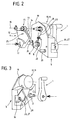
- a single pivoting actuating handle 1 is mounted integral with one of the ends of an operating shaft 2 carried by two bearings 3 and 4 immobilized in a transverse bore of a mechanical block 5 terminated on one side by a shoulder 6.
- This pivoting joystick determines two right and left control strokes.
- a torsion spring 8 At the opposite end of the operating axis 2 is mounted, on a plastic sleeve 7 fitted on said axis, a torsion spring 8 then a thick transmission part 9, for example metal, actuating a converter 10, sensor or displacement or position detector 11 and more generally a continuous or point converter for moving the lever into a variation of a physical quantity.
- a potentiometer By way of example, mention may be made of a potentiometer, an optical or capacitive encoder, a proximity detector, a step-by-step encoder, a magnetic sensor, a piezoresistive sensor, an inductive or Hall effect sensor, a photoelectric detector. or other equivalent.
- switches inductive or capacitive proximity detectors, limit switches or passage detectors, or any other suitable for the application.
- This transmission part is shaped for example in control sector 12 with an opening angle directed upwards, the upper part of which in an arc of a circle 13 is shaped according to a toothing 14 which meshes with a drive pinion 15 to axis 16 mounted at the end of the converter 10 constituted in the example represented by a rotary potentiometer referenced 11.
- the assembly of the transmission part 9 on the operating axis 2 is carried out by mounting and fixing the sector by its base which has for example a lower longitudinal opening 17 crossed by the corresponding flat end 18 of the shaped or machined operating axis in two opposite flats.
- This drive pinion 15 actuates the sensor or detector 11 of displacement or position, that is to say a functional element transforming the rotational movement of the pinion into a physical quantity which can be used directly or indirectly by electronic assembly.
- This displacement or position sensor or detector 11 is fixed to the upper part shaped as a wing 19 of the mechanical block 5 constituting the body of the manipulator device according to the invention.
- the mechanical block 5 comprises in the lower part of its rear face two stop rods 20 and 21 against one or the other of which arrive in contact-stop one or the other oblique edge corresponding to the control sector 12 thus limiting its angular deviation.
- the rear face of this mechanical block has also, for example in the alignment of the operating axes 2 and of the axis 16 of the pinion 15, a bearing stud 22 against which come into bearing contact on one or the other of its sides. one or the other end branch 23 and 24 of the torsion spring 8 mounted on the end of the operating shaft 2.
- the toothed control sector 12 carries in the middle part of its upper zone an actuating stud 25 whose geometric axis 16 is placed in alignment with the other two axes of operation and of the sensor drive pinion respectively.
- this actuating pin 25 is to be in permanent contact with one and the other of the branches of the torsion spring 8 which it selectively pushes in its pivoting movement.
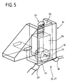
- One of the particularities of the manipulator device relates to a means 26 for splitting the right and left pivoting strokes.
- the fractionation mechanism 27 makes it possible to traverse the track or the path of the sensor in two displacements on either side of the midpoint.
- This mechanism consists of a cam 28 in the form of a ring secured to the operating axis, for example by pin.
- This cam 28 has two successive notches 29 and 30, that is to say slightly angularly offset and separated from each other by a slight flat 31 marking the middle position.
- notches 29 and 30 are of depth and profile adapted to present a passable hard point, that is to say a narrow zone of greater mechanical resistance, in the right and left stroke of the lever.
- This roller 32 is mounted for rotation by its axis 33 in two opposite notches existing on the lower end edge of a movable cage 34 slidingly housed in a longitudinal chamber 35 of a mechanical part 36 mounted on the mechanical block 5.
- This cage is mounted in constant elastic pressure stress downwards, that is to say towards the operating axis by a support spring 37 which permanently forces the roller 32 against the lateral surface of the cam 28.
- the roller is forced against the cam, rolls on the surface of the latter and thus causes additional mechanical resistance to the crossing of each notch. This allows each of the right and left strokes of the joystick to be divided into two areas separated by a more resistant point.
- each of the right and left strokes into two parts makes it possible to carry out in operation two degrees of control, for example a first and a second speed in one direction and in the other direction.
- a first voltage difference between a median voltage value, for example 2.5 volts for a maximum of 5 volts, and two intermediate values corresponding to the position of the notches and an additional deviation up to or near the maximum, for example 0.5 volts up to 4.5 volts.
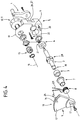
- the unitary manipulator device according to the invention is intended to equip a remote control unit 38, for example the unit as shown in FIG. 1 which comprises an upper front 39 for controlling the inclined end plane 40.
- This box is contained in a bag 41 and is intended for wireless remote control, for example of an overhead crane.
- It comprises three unitary manipulator devices 42, 43 and 44 making it possible to control along three axes, that is to say along three paths, each corresponding to a motor for actuating the crane and its devices: trolley, winch, etc. ..
- the third manipulator device 44 is used to control the winch motor fitted to the carriage.
- switches 45, 46 and 47 Other functions are provided in this box, such as fulfilled by switches 45, 46 and 47.
- An emergency stop button 48 is located on the side of the upper face of the housing.
- the invention relates to a method for making wireless remote control orders and to the use of a joystick associated with a sensor, a detector or a contactor for control a wireless remote control transmitter for remote actuation of a functional unit.
- the method and the application relate to the control of a remote control transmitter using a single pivoting joystick corresponding to a single channel or to a single control axis.
- the method consists in using a single lever pivoting to the right and to the left from a midpoint to mechanically actuate a detector or a sensor of position or angular or other displacement, or a detector or a proximity switch of passage or limit switch to initiate orders to a wireless remote control transmitter.
- the stroke of the lever in each of its movements of movement to the left or to the right is divided into at least two distinct and successive ranges of use.
- This first range is followed by a second range of use after the passage of a passable hard point in the pivoting of the lever to a predetermined angular position.
- This second range is used to control the passage to a second fixed or variable speed, for example in proportion to the angular displacement.
- the angular control zone is divided on either side of the median position corresponding to the midpoint into a first control range used for operating at a first fixed or variable speed and into a second control range used for switching to a second fixed or variable speed.
- a variable speed one of the variations envisaged is a variation proportional to the angular deviation of the lever relative to its median position.
- the passage between the first range and the second range is carried out in the form of a point or a zone of greater mechanical resistance to displacement, for example, a hard point that can be crossed.
Landscapes
- Manipulator (AREA)
- Mechanical Control Devices (AREA)
Priority Applications (2)
| Application Number | Priority Date | Filing Date | Title |
|---|---|---|---|
| FR929200918A FR2688959B1 (fr) | 1992-01-24 | 1992-01-24 | Dispositif manipulateur unitaire pour la telecommande sans fil d'une unite fonctionnelle. |
| EP93440079A EP0644565A1 (de) | 1992-01-24 | 1993-09-22 | Einheitlicher handhabungsvorrichtung für Drahtloser Fernsteuerung einer funktionellen Einheit |
Applications Claiming Priority (2)
| Application Number | Priority Date | Filing Date | Title |
|---|---|---|---|
| FR929200918A FR2688959B1 (fr) | 1992-01-24 | 1992-01-24 | Dispositif manipulateur unitaire pour la telecommande sans fil d'une unite fonctionnelle. |
| EP93440079A EP0644565A1 (de) | 1992-01-24 | 1993-09-22 | Einheitlicher handhabungsvorrichtung für Drahtloser Fernsteuerung einer funktionellen Einheit |
Publications (1)
| Publication Number | Publication Date |
|---|---|
| EP0644565A1 true EP0644565A1 (de) | 1995-03-22 |
Family
ID=26134777
Family Applications (1)
| Application Number | Title | Priority Date | Filing Date |
|---|---|---|---|
| EP93440079A Withdrawn EP0644565A1 (de) | 1992-01-24 | 1993-09-22 | Einheitlicher handhabungsvorrichtung für Drahtloser Fernsteuerung einer funktionellen Einheit |
Country Status (2)
| Country | Link |
|---|---|
| EP (1) | EP0644565A1 (de) |
| FR (1) | FR2688959B1 (de) |
Cited By (1)
| Publication number | Priority date | Publication date | Assignee | Title |
|---|---|---|---|---|
| EP0928579A3 (de) * | 1997-12-16 | 2002-01-30 | Dewert Antriebs- und Systemtechnik GmbH & Co. KG | Möbelantrieb |
Families Citing this family (2)
| Publication number | Priority date | Publication date | Assignee | Title |
|---|---|---|---|---|
| CN112429641A (zh) * | 2020-10-26 | 2021-03-02 | 中国船舶重工集团应急预警与救援装备股份有限公司 | 一种机械化站台的电气操控装置 |
| DE102022115160A1 (de) | 2022-06-17 | 2023-12-28 | Fraunhofer-Gesellschaft zur Förderung der angewandten Forschung eingetragener Verein | Einhand-Bedieneinrichtung |
Citations (6)
| Publication number | Priority date | Publication date | Assignee | Title |
|---|---|---|---|---|
| FR984577A (fr) * | 1949-02-12 | 1951-07-09 | Rode Stucky Ets | Dispositif de commande d'organes de commutation pour appareils récepteurs de t. s. f. |
| US3906369A (en) * | 1974-09-18 | 1975-09-16 | R O Products Inc | Function switch arrangement for hand-held remote control unit |
| FR2453488A1 (fr) * | 1979-04-06 | 1980-10-31 | Frankl & Kirchner | Dispositif d'actionnement pour un commutateur de commande |
| DE8101134U1 (de) * | 1981-01-19 | 1981-06-25 | Bär Elektrowerke KG, 5885 Schalksmühle | Elektrischer Schalter |
| JPS58122424A (ja) * | 1982-01-13 | 1983-07-21 | Nec Home Electronics Ltd | ジヨイステイツク |
| EP0341070A2 (de) * | 1988-05-04 | 1989-11-08 | Dexion Group Plc | Steuereinrichtung für einen Kran mit Fahrer |
-
1992
- 1992-01-24 FR FR929200918A patent/FR2688959B1/fr not_active Expired - Fee Related
-
1993
- 1993-09-22 EP EP93440079A patent/EP0644565A1/de not_active Withdrawn
Patent Citations (6)
| Publication number | Priority date | Publication date | Assignee | Title |
|---|---|---|---|---|
| FR984577A (fr) * | 1949-02-12 | 1951-07-09 | Rode Stucky Ets | Dispositif de commande d'organes de commutation pour appareils récepteurs de t. s. f. |
| US3906369A (en) * | 1974-09-18 | 1975-09-16 | R O Products Inc | Function switch arrangement for hand-held remote control unit |
| FR2453488A1 (fr) * | 1979-04-06 | 1980-10-31 | Frankl & Kirchner | Dispositif d'actionnement pour un commutateur de commande |
| DE8101134U1 (de) * | 1981-01-19 | 1981-06-25 | Bär Elektrowerke KG, 5885 Schalksmühle | Elektrischer Schalter |
| JPS58122424A (ja) * | 1982-01-13 | 1983-07-21 | Nec Home Electronics Ltd | ジヨイステイツク |
| EP0341070A2 (de) * | 1988-05-04 | 1989-11-08 | Dexion Group Plc | Steuereinrichtung für einen Kran mit Fahrer |
Non-Patent Citations (1)
| Title |
|---|
| PATENT ABSTRACTS OF JAPAN vol. 7, no. 234 (P - 230) 18 October 1983 (1983-10-18) * |
Cited By (1)
| Publication number | Priority date | Publication date | Assignee | Title |
|---|---|---|---|---|
| EP0928579A3 (de) * | 1997-12-16 | 2002-01-30 | Dewert Antriebs- und Systemtechnik GmbH & Co. KG | Möbelantrieb |
Also Published As
| Publication number | Publication date |
|---|---|
| FR2688959B1 (fr) | 1994-09-02 |
| FR2688959A1 (fr) | 1993-09-24 |
Similar Documents
| Publication | Publication Date | Title |
|---|---|---|
| EP2163853B1 (de) | Ortsveränderliches Elektrowerkzeug, das mit einer Vorrichtung ausgestattet ist, mit der die relative Position zwischen zwei Organen des besagten Werkzeugs bestimmt werden kann, von denen mindestens eines beweglich ist | |
| FR2534412A1 (fr) | Interrupteur electrique avec arret de course du levier de commande en cas de soudure des contacts | |
| EP0189338B1 (de) | Vorrichtung zur Detektion eines Gangwechsels zum Steuern einer mit einem Getriebe verbundenen Kupplung | |
| FR2682924A1 (fr) | Dispositif de commande de direction d'un vehicule. | |
| EP1615250B1 (de) | Betätigungsvorrichtung mit magnetischer Indexierung | |
| FR2656574A1 (fr) | Phare pour vehicule a faisceau orientable. | |
| EP0644565A1 (de) | Einheitlicher handhabungsvorrichtung für Drahtloser Fernsteuerung einer funktionellen Einheit | |
| FR2648580A1 (fr) | Procede pour etalonner un dispositif de telecommande electrique du type manipulateur ou analogue, et dispositif agence pour mettre en oeuvre ce procede | |
| FR2801023A1 (fr) | Organe de direction a actionnement a la main pour chariot de manutention | |
| FR2550115A1 (fr) | Dispositif de serrage | |
| EP0313470B1 (de) | Kupplungsstange mit Kontakt für die Steuerung des Fluges eines Luftfahrzeuges | |
| EP1201851B1 (de) | Türgriffanordnung für eine Schiebetür eines Kraftfahrzeuges | |
| FR2969774A1 (fr) | Bouton et dispositif de commande multifonction | |
| FR2611549A3 (fr) | Cisaille motorisee auto-alimentee | |
| FR2743795A1 (fr) | Timon pour chariot de manutention | |
| FR2716514A1 (fr) | Dispositif de transmission d'énergie de commande mécanique. | |
| EP0402216A1 (de) | Vorrichtung zur krummliniegen Bewegung eines Gegenstandes in Berührung mit einer Fläche, insbesondere einer konvexen Fläche | |
| FR2617331A1 (fr) | Bloc de contact auxiliaire utilisable sur des appareils electromecaniques de tailles differentes | |
| WO2002099825A1 (fr) | Dispositif de commande pour vehicule automobile destine notamment a piloter un ordinateur de bord | |
| FR2575845A1 (fr) | Manipulateur de commande resistant aux chocs | |
| EP0285517B1 (de) | Mit dem Daumen über Bowdenzug betätigte Getriebeschaltvorrichtung | |
| EP0383369B1 (de) | Anordnung bestehend aus einer Drehklappe und einem Antriebsorgan, verbunden durch ein Hebelgestänge | |
| EP1486376B1 (de) | Steueranordnung zum Aktivieren bzw. Deaktivieren von Funktionen eines Fahrzeuges | |
| EP2651693B1 (de) | Unter dem lenkrad montiertes steuermodul | |
| EP4697126A1 (de) | Befehlseingabevorrichtung mit mindestens einem steuerhebel mit endstellungssensor |
Legal Events
| Date | Code | Title | Description |
|---|---|---|---|
| PUAI | Public reference made under article 153(3) epc to a published international application that has entered the european phase |
Free format text: ORIGINAL CODE: 0009012 |
|
| AK | Designated contracting states |
Kind code of ref document: A1 Designated state(s): BE CH DE ES IT LI |
|
| RHK1 | Main classification (correction) |
Ipc: H01H 9/02 |
|
| STAA | Information on the status of an ep patent application or granted ep patent |
Free format text: STATUS: THE APPLICATION IS DEEMED TO BE WITHDRAWN |
|
| 18D | Application deemed to be withdrawn |
Effective date: 19950923 |