EP0644631A1 - Kollektor für Wechselstromgenerator hauptsächlich für Kraftfahrzeuge - Google Patents
Kollektor für Wechselstromgenerator hauptsächlich für Kraftfahrzeuge Download PDFInfo
- Publication number
- EP0644631A1 EP0644631A1 EP94402048A EP94402048A EP0644631A1 EP 0644631 A1 EP0644631 A1 EP 0644631A1 EP 94402048 A EP94402048 A EP 94402048A EP 94402048 A EP94402048 A EP 94402048A EP 0644631 A1 EP0644631 A1 EP 0644631A1
- Authority
- EP
- European Patent Office
- Prior art keywords
- channel
- wire
- connection element
- tabs
- notch
- Prior art date
- Legal status (The legal status is an assumption and is not a legal conclusion. Google has not performed a legal analysis and makes no representation as to the accuracy of the status listed.)
- Granted
Links
- 238000004804 winding Methods 0.000 claims description 16
- 239000004020 conductor Substances 0.000 claims description 5
- 239000011810 insulating material Substances 0.000 claims description 4
- RYGMFSIKBFXOCR-UHFFFAOYSA-N Copper Chemical compound [Cu] RYGMFSIKBFXOCR-UHFFFAOYSA-N 0.000 description 8
- 229910052802 copper Inorganic materials 0.000 description 8
- 239000010949 copper Substances 0.000 description 8
- 238000003466 welding Methods 0.000 description 7
- 238000004519 manufacturing process Methods 0.000 description 3
- 238000004873 anchoring Methods 0.000 description 2
- 238000005520 cutting process Methods 0.000 description 2
- 230000005284 excitation Effects 0.000 description 2
- 238000012423 maintenance Methods 0.000 description 2
- 239000000463 material Substances 0.000 description 2
- 239000002184 metal Substances 0.000 description 2
- 229910052751 metal Inorganic materials 0.000 description 2
- 230000010287 polarization Effects 0.000 description 2
- 210000002105 tongue Anatomy 0.000 description 2
- 238000009825 accumulation Methods 0.000 description 1
- 230000000295 complement effect Effects 0.000 description 1
- 238000010276 construction Methods 0.000 description 1
- 238000002788 crimping Methods 0.000 description 1
- 230000006866 deterioration Effects 0.000 description 1
- 230000009977 dual effect Effects 0.000 description 1
- 239000000428 dust Substances 0.000 description 1
- 230000000694 effects Effects 0.000 description 1
- 238000007667 floating Methods 0.000 description 1
- 238000010438 heat treatment Methods 0.000 description 1
- 238000002347 injection Methods 0.000 description 1
- 239000007924 injection Substances 0.000 description 1
- 230000004048 modification Effects 0.000 description 1
- 238000012986 modification Methods 0.000 description 1
- 238000000465 moulding Methods 0.000 description 1
- 239000000523 sample Substances 0.000 description 1
- 230000006641 stabilisation Effects 0.000 description 1
- 238000011105 stabilization Methods 0.000 description 1
- 229920001187 thermosetting polymer Polymers 0.000 description 1
- 239000002562 thickening agent Substances 0.000 description 1
- 230000007704 transition Effects 0.000 description 1
Images


Classifications
-
- H—ELECTRICITY
- H01—ELECTRIC ELEMENTS
- H01R—ELECTRICALLY-CONDUCTIVE CONNECTIONS; STRUCTURAL ASSOCIATIONS OF A PLURALITY OF MUTUALLY-INSULATED ELECTRICAL CONNECTING ELEMENTS; COUPLING DEVICES; CURRENT COLLECTORS
- H01R39/00—Rotary current collectors, distributors or interrupters
- H01R39/02—Details for dynamo electric machines
- H01R39/34—Connections of conductor to slip-ring
-
- H—ELECTRICITY
- H02—GENERATION; CONVERSION OR DISTRIBUTION OF ELECTRIC POWER
- H02K—DYNAMO-ELECTRIC MACHINES
- H02K13/00—Structural associations of current collectors with motors or generators, e.g. brush mounting plates or connections to windings; Disposition of current collectors in motors or generators; Arrangements for improving commutation
- H02K13/02—Connections between slip-rings and windings
Definitions
- the present invention relates generally to the connection of wire ends on connection elements, in particular in the context of the connection of an excitation winding to slip rings in a motor vehicle alternator, and relates to more particularly a new connection element forming wire clamp for the maintenance thereof during a subsequent welding step, in particular electric welding.
- connection element for the end of the wire may comprise two tabs or tongues facing each other between which the wire is positioned, with a view to pinching the latter when the two tongues are brought together.
- Such a connection element may also include one or more holes in which the end of the wire is engaged with a view to welding it.
- connection elements suffer from a number of drawbacks, however.
- a wire clamp it proves difficult to ensure reliably the maintenance of the wire between the two tabs for welding.
- connection elements with wire passage hole (s) the positioning of the end of the wire is tedious, in particular in the case where access to the connection element is difficult.
- connection elements More generally, it is extremely difficult with known connection elements to achieve reliable positioning of a wire end using robotic means.
- connection element for the end of the wire of the type comprising a channel for the said end of the wire, defined between two tabs located opposite and connected to each other by a connecting part. constituting the bottom of the channel, said legs being intended to be folded one towards the other for pinching said end of wire, characterized in that at least one of the tabs has, at at least one lateral edge and near said connecting part, a notch for receiving a part of the wire end bent at about 180 ° and located between a first part of the wire end extending inside the channel and a second part of the wire end extending outside of the canal.
- the invention also relates to an attached collector for an alternator, in particular for a motor vehicle, of the type produced by overmolding of insulating material on electrically conductive elements, and comprising a first generally cylindrical part comprising on its outer surface two slip rings, a second part comprising two elements for connection with the ends of the wires of a winding, and an intermediate part for electrical and mechanical connection between the first and second parts, comprising two arms each consisting of a conductive part for connection between ring and element connection embedded in the insulating material, characterized in that it comprises two connection elements as defined above.
- the invention proposes an alternator, in particular for a motor vehicle, characterized in that it comprises, on a projecting shaft, an attached collector as defined above.
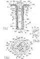
- FIG. 1 there is shown a part forming a collector for an alternator, at an intermediate stage of its manufacture.
- the part is produced by overmolding of plastic material, preferably thermosetting, on conductive parts, for example copper, intended to form firstly two cylindrical contact rings with brushes, secondly two elements connection with two ends of a rotor winding of the alternator, and thirdly two electrical connection elements between the two rings and the two connection elements.
- plastic material preferably thermosetting
- conductive parts for example copper
- the cylindrical rings are initially made up of a single hollow copper cylinder 10 which, at the end of the production of the part, is cut circularly over its entire thickness in its middle region to form the two rings 10a, 10b electrically isolated from each other ( Figure 9).
- connection elements respectively 14a, 14b, comprise two facing tabs 15, 15 which define between them a flared central channel 17 and which are connected together by a part 15 'in the form of a truncated cone sector , defining the bottom of the channel. This channel is intended to receive one end of the winding.
- the associated connecting element, respectively 12a, 12b, extends radially inwards from the narrowest side of the part 15.
- Each tab 15 has, in the region of the bottom of the channel and on its edge turned radially inwards, a notch in this case semi-circular 16.
- each tab 15 has on its inner face a generally rounded boss 151, preferably produced by stamping, for the purposes explained below.
- FIG. 9 illustrates the end of a winding wire FB which has been placed in the connection element 14a, the part 1 occupying in this case an angular position such that the two connection elements 14a, 14b are vertically aligned.
- the wire is bent over 180 ° and its free, descending end is engaged in the channel defined between the legs 15, while its elbow is housed in one of the notches 16.
- a crimping or pinching is carried out by bringing together with a tool the two tabs 15, which pinch the free end portion of the wire, this step being followed by welding, for example electric.
- welding for example electric.
- connection element such as 14a has many advantages.
- the flared shape of the channel delimited by the lugs 15 and the bottom 15 ′ exerts a guiding effect during the introduction of the free end of the wire.
- This flared shape also allows, because the channel 17 has its greatest width at the connection of the element 14a or 14b with the rest of the metal part, to limit the necking phenomena when folding the legs 15 to exert the pinch.
- the notch 16 which receives the bent region of the wire ensures stabilization of the wire in the position illustrated on the Figure 9, in particular preventing it from disengaging from the channel by its open side.
- tabs 15 ensure a firm but not sharp pinching of the wire, to ensure good mechanical strength before the welding step.
- the connecting elements 12a, 12b each comprise a part in the form of a cylinder portion, respectively 121a, 121b, welded on the inner face of the part 10 intended to form the rings, a first generally straight intermediate part, respectively 122a, 122b , the section of which is U-shaped at least over a substantial part of its length (see in particular FIG. 3, right part, and FIG. 7), and offset radially inwards relative to the respective associated part 121a, 121b, and a second intermediate part, of flat section, curved at an angle of approximately 90 °, respectively 123a, 123b, the radially oriented end of which extends into the respective connection element 14a, 14b.
- the profile variations of the parts 121a-123a and 121b-123b take place gradually.
- the parts 121a, 121b are welded to the part 10 respectively in its close region and in its region remote from the connecting elements 12a, 12b, so that after the aforementioned cutting, the connecting element 14a is only connected to the ring 10a, and that the connection element 14b is only connected to the ring 10b.
- the U-shaped section of the straight intermediate parts makes it possible to increase their rigidity, in order to minimize any risk of deviation from inadvertent positioning during the overmolding step, and in particular to avoid any risk of short circuit between the part of the cylinder 10 which will become the inner ring 10a and the adjacent intermediate part 122b.
- each curved intermediate portion 123a, 123b comprises, in the vicinity of the respective connection element 14a, 14b, a wider region, respectively 124a, 124b, defining two lateral anchoring tabs 1241 and in which is formed a circular through hole 1242.
- This hole is intended to cooperate with arrangements (fixed or mobile) of the mold so as to precisely position the connection elements 14a, 14b during the overmolding step.
- a part 20 of generally cylindrical shape which extends inside the copper cylinder 10 completely covering its inner face as well as the conductive plates 121a, 121b and the sections of the intermediate parts 122a, 122b located inside said cylinder.
- This cylinder 20 is extended, in the direction of the connection elements 14a, 14b by another cylindrical part 22, the external surface of which comes flush with the external surface of the copper cylinder 10.
- the parts 20, 22 define a central cylindrical bore 24 provided over its entire length with two grooves 26, 26 'of generally rectangular section, diametrically opposite and occupying the same angular positions, relative to the axis of the part, as the elements connection 14a, 14b.
- This grooved bore is intended to receive a shaft, of complementary shape, from the alternator, on which the part 1 is force fitted.
- the cylindrical part 20 is extended by a small flange 28 with bevelled outer and inner edges, respectively 28a and 28b. Between the bevelled outer edge 28a and the copper cylinder 10, the part 28 has a cylindrical surface slightly set back from the exterior surface of said cylinder 10.
- this part 28 are formed three notches 30, 30 'and 30' 'whose depth is equal to the length of the part 28 in the axial direction, that is to say that the bottom of these notches reveals the edge of the copper cylinder.
- One of these three notches 30 is aligned with the lower groove 26, while the other two, 30 'and 30' ', are angularly offset in this case by 120 ° on either side of the notch 30 .
- the notches 30, 30 ', 30' ' have a dual role.
- the force fitting of the part 1 on the alternator shaft is carried out, for example in an automated manner, by exerting a very great axial force on the part 1 on the side of the part 28.
- the notches 30, 30 ', 30' ' are intended to receive three pressure fingers from the automaton, which in this way will exert the force on the part by acting not on its plastic parts, but on the edge , turned towards the part 28, of the metal cylinder 10. In this way, this effort is exerted without risk of deterioration of the plastic of the part, the mechanical resistance of which is of course much lower than that of copper.
- notches 30, 30 ', 30'' make it possible to provide a polarization as for the angular positioning of part 1 on the alternator before its fitting.
- the notches 30, 30 ', 30' ' allow the pairing of these connections to be carried out, the correct angular position of the part 1, among its two possible positions offset by 180 °, being determined for example by means of one or more probes associated with robotic assembly equipment, or even visually during manual operations.
- the part 1 after overmolding further comprises two plastic branches 32a, 32b in which are completely embedded the conductive connecting parts 122a, 123a and 122b, 123b, respectively, and a part in ring shape 34 of axis coincident with that of the cylindrical parts 10, 20, 22, connected to these parts by said branches and located at the connection elements 14a, 14b.
- each branch 32a, 32b comprises a rectilinear section, respectively 321a, 321b, and a section curved over 90 °, respectively 322a, 322b, conforming to the shape of the curved intermediate parts 123a, 123b made of conductive material.
- the branches 32a, 32b are connected radially and in positions diametrically opposite the ring 34, at the level of the connection elements 14a, 14b.
- each branch 32a, 32b in the transition region between its rectilinear section and its curved section, exhibits an outward offset noted respectively 323a, 323b.
- each straight section 321a, 321b is located in the extension, in an axial direction, of the inner face of a groove 26, 26 'of the bore 24, while the outer face of each straight section has a profile in the shape of an arc of a circle and is located in the extension, in an axial direction, of the external face of the part 22.
- the ring 34 comprises, in two diametrically opposite positions and offset by 90 ° relative to the connection elements 14a, 14b, two thickeners 341 directed outwards, and in the external surface of which two slightly concave recesses 342 are formed respectively.
- Two other extra thicknesses 343, also directed outwards, are formed in the ring 34 at the connection elements 14a, 14b, so as to partially trap the anchoring lugs 1241.
- these extra thicknesses 343 are also formed respectively two recesses 344 allowing to leave the holes circulars 1242 released.
- the production of the ring 34 during the overmolding step makes it possible to stiffen the part 1 in the region of the connection elements 14a, 14b, ensuring that their mutual distance in the radial direction is well determined. Indeed, the presence of the alternator fan not far from these elements 14a, 14b after fitting the part requires positioning these elements precisely in the radial direction. Furthermore, the ring 34 makes it possible to guarantee the absence of any contact between the elements 14a, 14b and an enlarged part AR1 of the alternator shaft AR (see FIG. 9), around which the ring comes position, especially during expansion phenomena due to heating or accumulation of dust in this region of the alternator.
- the injection of the overmolding material is preferably carried out at the level of this ring, and in particular at the level of the extra thicknesses 341.
- the concave surfaces 342 provided laterally and diametrically opposite are used for gripping the part by a robot with a view to press fit on an alternator shaft.
- the part can be gripped according to two possible orientations, mutually offset by 180 °, and it was indicated above how the notches 30, 30 ', 30' 'made it possible to ensure a polarization to choose the orientation which is suitable for supply the winding with the correct polarity.
- the recesses 323a, 323b which project radially outward from the cylindrical surface defined by the cylinder 10 and its insulating extension 22, make it possible, when mounting the part on certain alternators, to define an axial stop for a ball bearing provided between the alternator shaft and its casing to constitute the rear bearing of the alternator.
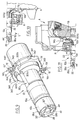
- FIGS 10 and 11 show a part as described above mounted respectively on two alternators A of different models.
- the alternator shaft is designated by AR, and a bearing for this shaft by R.
Landscapes
- Engineering & Computer Science (AREA)
- Power Engineering (AREA)
- Synchronous Machinery (AREA)
- Connections Effected By Soldering, Adhesion, Or Permanent Deformation (AREA)
- Motor Or Generator Current Collectors (AREA)
- Connector Housings Or Holding Contact Members (AREA)
Applications Claiming Priority (2)
| Application Number | Priority Date | Filing Date | Title |
|---|---|---|---|
| FR9311041 | 1993-09-16 | ||
| FR9311041A FR2710197B1 (fr) | 1993-09-16 | 1993-09-16 | Collecteur rapporté pour alternateur notamment de véhicule automobile. |
Publications (2)
| Publication Number | Publication Date |
|---|---|
| EP0644631A1 true EP0644631A1 (de) | 1995-03-22 |
| EP0644631B1 EP0644631B1 (de) | 1998-04-01 |
Family
ID=9450931
Family Applications (1)
| Application Number | Title | Priority Date | Filing Date |
|---|---|---|---|
| EP94402048A Expired - Lifetime EP0644631B1 (de) | 1993-09-16 | 1994-09-14 | Kollektor für Wechselstromgenerator hauptsächlich für Kraftfahrzeuge |
Country Status (8)
| Country | Link |
|---|---|
| US (1) | US5486732A (de) |
| EP (1) | EP0644631B1 (de) |
| JP (1) | JP3364847B2 (de) |
| CN (1) | CN1037049C (de) |
| DE (1) | DE69409317T2 (de) |
| ES (1) | ES2115177T3 (de) |
| FR (1) | FR2710197B1 (de) |
| TR (1) | TR28460A (de) |
Families Citing this family (31)
| Publication number | Priority date | Publication date | Assignee | Title |
|---|---|---|---|---|
| CN100483896C (zh) * | 2002-06-25 | 2009-04-29 | 瓦莱奥万都电子系统(韩国)株式会社 | 汽车交流发电机接头 |
| DE102004028781A1 (de) * | 2004-06-16 | 2006-01-12 | Ascom D.O.O. | Elektrische Maschine |
| ES2317579T3 (es) * | 2005-09-23 | 2009-04-16 | Unilever N.V. | Productos aireados de ph bajo. |
| CA2616276C (en) * | 2005-09-23 | 2014-03-18 | Unilever Plc | Aerated products with reduced creaming |
| ES2351479T3 (es) * | 2006-01-31 | 2011-02-07 | Unilever Plc | Composiciones aireadas que comprenden hidrofobina. |
| EP2129238A1 (de) * | 2007-03-26 | 2009-12-09 | Unilever N.V. | Warme belüftete lebensmittel, die lösliche und/oder unlösliche feststoffe enthalten und herstellungsverfahren dafür |
| MX2009010364A (es) * | 2007-03-26 | 2009-10-16 | Unilever Nv | Productos alimenticios aereados que estan tibios o que han sido calentados y metodos para producirlos. |
| US20100291630A1 (en) * | 2007-10-18 | 2010-11-18 | Andrew Richard Cox | Method for producing a foaming agent |
| US20100112139A1 (en) * | 2008-03-28 | 2010-05-06 | Conopco, Inc., D/B/A Unilever | Foaming Agents Comprising Hydrophobin |
| JP2012505645A (ja) * | 2008-10-16 | 2012-03-08 | ユニリーバー・ナームローゼ・ベンノートシヤープ | 消泡剤を含むハイドロフォビン溶液 |
| ES2395224T3 (es) * | 2008-12-16 | 2013-02-11 | Unilever Nv | Procedimiento para extraer hidrofobina de una disolución |
| US8357420B2 (en) * | 2009-05-29 | 2013-01-22 | Conopco, Inc. | Oil-in-water emulsion |
| US8394444B2 (en) * | 2009-05-29 | 2013-03-12 | Conopco, Inc. | Oil-in-water emulsion |
| CA2704702C (en) * | 2009-06-02 | 2018-06-12 | Unilever Plc | Aerated baked products |
| FR2952767B1 (fr) | 2009-11-13 | 2012-06-01 | Valeo Equip Electr Moteur | Rotor a griffes equipe d'un isolant d'un bobinage d'excitation et d'aimants et machine electrique tournante equipee d'un tel rotor |
| FR2984627B1 (fr) | 2011-12-20 | 2016-06-24 | Valeo Equip Electr Moteur | Rotor a poles saillants comportant une piece de guidage de fils de bobinage, piece de guidage de fils de bobinage et procede de bobinage associes |
| FR2984625B1 (fr) | 2011-12-20 | 2016-06-24 | Valeo Equip Electr Moteur | Rotor a poles saillants comportant des flasques de maintien des chignons de bobinages et flasques de maintien associes |
| FR2984630B1 (fr) | 2011-12-20 | 2016-06-24 | Valeo Equip Electr Moteur | Rotor a poles saillants comportant des flasques de maintien des chignons de bobinages et flasques de maintien associes |
| FR2984626B1 (fr) | 2011-12-20 | 2014-01-17 | Valeo Equip Electr Moteur | Rotor a poles saillants comportant un dispositif d'isolation de bobinages et dispositif d'isolation de bobinages associe |
| FR2999821B1 (fr) | 2012-12-17 | 2018-11-02 | Valeo Equipements Electriques Moteur | Rotor a griffes dote d'un isolant d'un bobinage d'excitation et une machine electrique tournante equipee d'un tel rotor |
| FR3006517B1 (fr) * | 2013-06-04 | 2018-03-02 | Valeo Equipements Electriques Moteur | Machine electrique tournante pour vehicule automobile |
| CN103660612B (zh) * | 2013-12-04 | 2016-02-24 | 攀钢集团攀枝花钢钒有限公司 | 中心罩装置及钢轨打印机 |
| FR3015795B1 (fr) | 2013-12-20 | 2017-08-25 | Valeo Equip Electr Moteur | Interconnecteur pour stator de machine electrique et stator de machine electrique comportant un tel interconnecteur |
| JP6250159B2 (ja) * | 2014-06-18 | 2017-12-20 | 三菱電機株式会社 | 交流発電機のスリップリング装置 |
| BR112017008002A2 (pt) * | 2014-12-01 | 2018-02-20 | Mitsubishi Electric Corporation | rotor de uma máquina elétrica rotativa, e, máquina elétrica rotativa. |
| FR3040561B1 (fr) | 2015-09-01 | 2017-08-25 | Valeo Equip Electr Moteur | Machine electrique tournante muni d'un rotor comprenant des poles en forme de griffe |
| FR3043506B1 (fr) | 2015-11-09 | 2017-11-17 | Valeo Equip Electr Moteur | Machine electrique tournante muni d'un stator |
| FR3045238A1 (fr) | 2015-12-14 | 2017-06-16 | Valeo Equip Electr Moteur | Ensemble regulateur de tension avec porte-balais pour machine electrique tournante |
| FR3076407B1 (fr) * | 2018-01-02 | 2020-06-19 | Valeo Systemes D'essuyage | Rotor de machine electrique tournante et procede de fabrication associe |
| FR3116954B1 (fr) | 2020-12-02 | 2023-08-25 | Valeo Equip Electr Moteur | Collecteur pour machine électrique tournante |
| FR3153199A1 (fr) * | 2023-09-20 | 2025-03-21 | Renault S.A.S. | Dispositif et procédé d’accrochage d’un fil de bobinage sur un collecteur rotatif, collecteur rotatif et moteur à rotor bobiné associés |
Citations (4)
| Publication number | Priority date | Publication date | Assignee | Title |
|---|---|---|---|---|
| US2157007A (en) * | 1935-07-12 | 1939-05-02 | Ibm | Conductor terminal |
| GB1416444A (en) * | 1972-06-13 | 1975-12-03 | Espanola Magnetos Fab | Alternators for automobile vehicles |
| GB2091497A (en) * | 1980-12-31 | 1982-07-28 | Paris & Du Rhone | Reinforced collector of the contracted type for a rotating electrical machine |
| EP0094163A1 (de) * | 1982-05-06 | 1983-11-16 | LUCAS INDUSTRIES public limited company | Herstellung von Schleifringen |
Family Cites Families (2)
| Publication number | Priority date | Publication date | Assignee | Title |
|---|---|---|---|---|
| GB2198890B (en) * | 1986-12-11 | 1992-01-08 | Johnson Electric Ind Mfg | A commutator for an electric motor |
| GB9208980D0 (en) * | 1992-04-25 | 1992-06-10 | Johnson Electric Sa | An assembled commutator |
-
1993
- 1993-09-16 FR FR9311041A patent/FR2710197B1/fr not_active Expired - Lifetime
-
1994
- 1994-09-06 TR TR00889/94A patent/TR28460A/xx unknown
- 1994-09-08 CN CN94115136A patent/CN1037049C/zh not_active Expired - Lifetime
- 1994-09-12 US US08/304,361 patent/US5486732A/en not_active Expired - Lifetime
- 1994-09-14 DE DE69409317T patent/DE69409317T2/de not_active Expired - Fee Related
- 1994-09-14 EP EP94402048A patent/EP0644631B1/de not_active Expired - Lifetime
- 1994-09-14 ES ES94402048T patent/ES2115177T3/es not_active Expired - Lifetime
- 1994-09-16 JP JP22154094A patent/JP3364847B2/ja not_active Expired - Lifetime
Patent Citations (4)
| Publication number | Priority date | Publication date | Assignee | Title |
|---|---|---|---|---|
| US2157007A (en) * | 1935-07-12 | 1939-05-02 | Ibm | Conductor terminal |
| GB1416444A (en) * | 1972-06-13 | 1975-12-03 | Espanola Magnetos Fab | Alternators for automobile vehicles |
| GB2091497A (en) * | 1980-12-31 | 1982-07-28 | Paris & Du Rhone | Reinforced collector of the contracted type for a rotating electrical machine |
| EP0094163A1 (de) * | 1982-05-06 | 1983-11-16 | LUCAS INDUSTRIES public limited company | Herstellung von Schleifringen |
Also Published As
| Publication number | Publication date |
|---|---|
| DE69409317T2 (de) | 1998-08-27 |
| EP0644631B1 (de) | 1998-04-01 |
| JP3364847B2 (ja) | 2003-01-08 |
| FR2710197B1 (fr) | 1995-12-08 |
| FR2710197A1 (fr) | 1995-03-24 |
| CN1104388A (zh) | 1995-06-28 |
| DE69409317D1 (de) | 1998-05-07 |
| US5486732A (en) | 1996-01-23 |
| CN1037049C (zh) | 1998-01-14 |
| TR28460A (tr) | 1996-07-04 |
| ES2115177T3 (es) | 1998-06-16 |
| JPH07211360A (ja) | 1995-08-11 |
Similar Documents
| Publication | Publication Date | Title |
|---|---|---|
| EP0644631B1 (de) | Kollektor für Wechselstromgenerator hauptsächlich für Kraftfahrzeuge | |
| EP0644630B1 (de) | Kollektor für einen Wechselstromgenerator, insbesondere für ein Kraftfahrzeug | |
| EP0644629B1 (de) | Kollektor für einen Wechselstromgenerator, insbesondere für ein Kraftfahrzeug | |
| FR2465323A1 (fr) | Connecteur de raccordement aux bornes de prise de courant d'une pile ou accumulateur electrique | |
| EP0374033B1 (de) | Elektrische Spulenanordnung, insbesondere Elektromagnet, mit einem Spulenkörper und einem Spulengehäuse | |
| WO1987002196A1 (fr) | Perfectionnements aux douilles de contact electrique | |
| FR2928043A1 (fr) | Collecteur electrique, notamment pour alternateur. | |
| FR2928042A1 (fr) | Collecteur electrique, notamment pour alternateur. | |
| FR2523366A1 (fr) | Support de fusible | |
| FR2929045A1 (fr) | Magnetron | |
| CH631293A5 (fr) | Contact electrique. | |
| EP3097634B1 (de) | Isolierungsvorrichtung für den kommutator der elektrischen maschine, zugehörige kommutator und lichtmaschine | |
| FR2497415A1 (fr) | Collecteur renforce du type retreint pour machine electrique tournante et son procede de fabrication | |
| FR2613880A1 (fr) | Rotor a bagues collectrices pour machine dynamo-electrique notamment alternateur de vehicule automobile et procede d'obtention d'un tel rotor | |
| WO2009106775A2 (fr) | Collecteur electrique, notamment pour alternateur | |
| FR2758661A1 (fr) | Dispositif de raccordement mecanique et de connexion electrique | |
| FR2928044A1 (fr) | Collecteur electrique, notamment pour alternateur. | |
| FR2930382A1 (fr) | Collecteur electrique, notamment pour alternateur. | |
| EP0395514B1 (de) | Sichereitszusammenbau eines Verbinders und einer Hochspannungslampe, besonders für Wagenbeleuchtung | |
| FR2504318A1 (fr) | Lame conductrice pour collecteurs de machines electriques tournantes et son procede de fabrication | |
| FR2754639A1 (fr) | Procede de fabrication d'un contact femelle de raccordement electrique et contact obtenu par un tel procede | |
| EP1925011B1 (de) | Wärmekraftmaschinenanlasserschalter mit verbesserten elektrischen verbindungsmitteln der wicklung | |
| FR2486660A1 (fr) | Emetteur d'impulsions capacitif | |
| EP0268502B1 (de) | Klammerförmiges Kabelendstück für Zündverteilerdeckel | |
| FR2631427A1 (fr) | Element chauffant pour un radiateur electrique utilise pour le chauffage de locaux, notamment de type continu |
Legal Events
| Date | Code | Title | Description |
|---|---|---|---|
| PUAI | Public reference made under article 153(3) epc to a published international application that has entered the european phase |
Free format text: ORIGINAL CODE: 0009012 |
|
| AK | Designated contracting states |
Kind code of ref document: A1 Designated state(s): DE ES GB IT |
|
| 17P | Request for examination filed |
Effective date: 19950703 |
|
| 17Q | First examination report despatched |
Effective date: 19960226 |
|
| GRAG | Despatch of communication of intention to grant |
Free format text: ORIGINAL CODE: EPIDOS AGRA |
|
| GRAG | Despatch of communication of intention to grant |
Free format text: ORIGINAL CODE: EPIDOS AGRA |
|
| GRAH | Despatch of communication of intention to grant a patent |
Free format text: ORIGINAL CODE: EPIDOS IGRA |
|
| GRAH | Despatch of communication of intention to grant a patent |
Free format text: ORIGINAL CODE: EPIDOS IGRA |
|
| GRAA | (expected) grant |
Free format text: ORIGINAL CODE: 0009210 |
|
| AK | Designated contracting states |
Kind code of ref document: B1 Designated state(s): DE ES GB IT |
|
| GBT | Gb: translation of ep patent filed (gb section 77(6)(a)/1977) |
Effective date: 19980402 |
|
| REF | Corresponds to: |
Ref document number: 69409317 Country of ref document: DE Date of ref document: 19980507 |
|
| ITF | It: translation for a ep patent filed | ||
| REG | Reference to a national code |
Ref country code: ES Ref legal event code: FG2A Ref document number: 2115177 Country of ref document: ES Kind code of ref document: T3 |
|
| PLBE | No opposition filed within time limit |
Free format text: ORIGINAL CODE: 0009261 |
|
| STAA | Information on the status of an ep patent application or granted ep patent |
Free format text: STATUS: NO OPPOSITION FILED WITHIN TIME LIMIT |
|
| 26N | No opposition filed | ||
| REG | Reference to a national code |
Ref country code: GB Ref legal event code: IF02 |
|
| PGFP | Annual fee paid to national office [announced via postgrant information from national office to epo] |
Ref country code: ES Payment date: 20030915 Year of fee payment: 10 |
|
| PG25 | Lapsed in a contracting state [announced via postgrant information from national office to epo] |
Ref country code: ES Free format text: LAPSE BECAUSE OF NON-PAYMENT OF DUE FEES Effective date: 20040915 |
|
| REG | Reference to a national code |
Ref country code: ES Ref legal event code: FD2A Effective date: 20040915 |
|
| PGFP | Annual fee paid to national office [announced via postgrant information from national office to epo] |
Ref country code: IT Payment date: 20080918 Year of fee payment: 15 |
|
| PGFP | Annual fee paid to national office [announced via postgrant information from national office to epo] |
Ref country code: GB Payment date: 20080822 Year of fee payment: 15 |
|
| PGFP | Annual fee paid to national office [announced via postgrant information from national office to epo] |
Ref country code: DE Payment date: 20080911 Year of fee payment: 15 |
|
| GBPC | Gb: european patent ceased through non-payment of renewal fee |
Effective date: 20090914 |
|
| PG25 | Lapsed in a contracting state [announced via postgrant information from national office to epo] |
Ref country code: DE Free format text: LAPSE BECAUSE OF NON-PAYMENT OF DUE FEES Effective date: 20100401 |
|
| PG25 | Lapsed in a contracting state [announced via postgrant information from national office to epo] |
Ref country code: GB Free format text: LAPSE BECAUSE OF NON-PAYMENT OF DUE FEES Effective date: 20090914 |
|
| PG25 | Lapsed in a contracting state [announced via postgrant information from national office to epo] |
Ref country code: IT Free format text: LAPSE BECAUSE OF NON-PAYMENT OF DUE FEES Effective date: 20090914 |