EP0644664B1 - Système pour adapter la caractéristique d'une unité de protection - Google Patents
Système pour adapter la caractéristique d'une unité de protection Download PDFInfo
- Publication number
- EP0644664B1 EP0644664B1 EP94104428A EP94104428A EP0644664B1 EP 0644664 B1 EP0644664 B1 EP 0644664B1 EP 94104428 A EP94104428 A EP 94104428A EP 94104428 A EP94104428 A EP 94104428A EP 0644664 B1 EP0644664 B1 EP 0644664B1
- Authority
- EP
- European Patent Office
- Prior art keywords
- characteristic
- working
- system processing
- processing units
- protection
- Prior art date
- Legal status (The legal status is an assumption and is not a legal conclusion. Google has not performed a legal analysis and makes no representation as to the accuracy of the status listed.)
- Expired - Lifetime
Links
Images


Classifications
-
- H—ELECTRICITY
- H04—ELECTRIC COMMUNICATION TECHNIQUE
- H04L—TRANSMISSION OF DIGITAL INFORMATION, e.g. TELEGRAPHIC COMMUNICATION
- H04L1/00—Arrangements for detecting or preventing errors in the information received
- H04L1/22—Arrangements for detecting or preventing errors in the information received using redundant apparatus to increase reliability
-
- H—ELECTRICITY
- H04—ELECTRIC COMMUNICATION TECHNIQUE
- H04B—TRANSMISSION
- H04B1/00—Details of transmission systems, not covered by a single one of groups H04B3/00 - H04B13/00; Details of transmission systems not characterised by the medium used for transmission
- H04B1/74—Details of transmission systems, not covered by a single one of groups H04B3/00 - H04B13/00; Details of transmission systems not characterised by the medium used for transmission for increasing reliability, e.g. using redundant or spare channels or apparatus
-
- H—ELECTRICITY
- H04—ELECTRIC COMMUNICATION TECHNIQUE
- H04J—MULTIPLEX COMMUNICATION
- H04J3/00—Time-division multiplex systems
- H04J3/02—Details
- H04J3/14—Monitoring arrangements
Definitions
- the present invention relates to a system for adjusting a characteristic of a protection unit when switching from one of a plurality of working units having different characteristics to the protection unit, typically, an N-to-one protection switching system which activates a protection unit instead of one of N working units when said one of the N working units fails, where N is an integer more than one.
- the system containing a plurality of working units and a protection unit as above, is usually used in terminal stations in transmission systems.
- a plurality of pieces of terminal equipment are provided for receiving and transmitting transmission signals transmitted through a plurality of transmission lines, and at least one protection unit is provided for substituting for one of the plurality of working units which fails.
- the respective working units are usually preset in different ways. Therefore, when one of the plurality of working units is substituted by the protection unit, the protection unit must to be set in the same manner as the substituted working unit.
- a fault in any channel is detected by a respective controller 4-1 to 4-n, to cause controller 9 to selectively operate the second switches 5-1 to 5-n, 5-P to select a correction line corresponding to the faulty active line Mi.
- An equal characteristic is obtained for each active line and the line is stably switched.
- EP-A-0 208 270 discloses a microwave relay station having parallel quadrature amplitude modulated (QAM) and frequency modulated (FM) channels.
- the station also includes a standby channel.
- the standby channel is used to increase the reliability of the transmission paths of the QAM and FM channels.
- the standby channel includes a detector circuit 6 which distinguishes between the two sorts of signals and controls the switching circuits 3-1 and 3-2 so that the signals in the standby channel are passed either via the QAM demodulator 4-2 to the standby channel transmitter 5-2 or directly to that transmitter, depending on whether the standby channel signals are detected as being QAM or FM signals, respectively.
- the characteristics of the standby channel are variable and selected according to the signals that the standby channel is required to pass in substitution for the defective channel.
- An object of the present invention is to provide a system for automatically setting a characteristic of a protection unit when switching from one of a plurality of working units having different characteristics to the protection unit.
- a system for processing a plurality of signals in parallel contains: a plurality of working-system processing units respectively provided corresponding to a plurality of input signals, for processing a signal input thereto and outputting the processed signal, where the plurality of working-system processing units further corresponding to a plurality of output signals, respectively; one or more protection-system processing units for processing a signal input thereto and outputting the processed signal; a first switch unit for receiving and supplying the plurality of input signals to the corresponding plurality of working-system processing units, respectively, in a first mode, and receiving and supplying at least one of the plurality of input signals to at least one of the above one or more protection-system processing units as at least one substitute for at least one of the plurality of working-system processing units, respectively, in a second mode; a second switch unit for receiving the processed signals output from the plurality of working-system processing units, and outputting the processed signals from the plurality of working-system processing units, as the corresponding pluralit
- each of the plurality of working-system processing units contains a characteristic information holding unit for holding information indicating the characteristic of the above each of the plurality of working-system processing units.
- the above system according to the second aspect of the present invention further contains a working characteristic reading unit for reading information on the characteristic of each of the plurality of working-system processing units.
- the system may further contain: a characteristic setting unit for holding control data therein and applying the control data to the variable-characteristic unit.
- the characteristic control unit may control the variable-characteristic unit by setting the control data in the characteristic setting unit.
- the characteristic setting unit may contain: a plurality of control data holding units, provided corresponding to the plurality of working-system processing units, each for holding and outputting the control data to be set in the characteristic setting unit in the corresponding one of the plurality of working-system processing units when the characteristic control unit controls the variable-characteristic unit; and a selector for selecting the control data for one of the plurality of working-system processing units, and applying the selected control data to the variable-characteristic unit.
- FIG. 1 is a diagram illustrating a portion of a construction of a portion of a conventional terminal station containing the N-to-one protection switch system, where N is an integer more than one.
- the terminal station contains a plurality (N) of pieces of working terminal equipment 52 1 to 52 N respectively connected to a plurality of (tributary) transmission lines 51 1 to 51 N , a piece of protection terminal equipment 53, a switch control unit 54, a pair of protection switches 55 1 and 55 2 provided on both sides of the row of the N pieces of working terminal equipment 52 1 to 52 N and the piece of protection terminal equipment 53, and a demultiplexer 58 which demultiplexes multiplexed transmission signals at a high transmission rate.
- the pieces of working terminal equipment 52 1 to 52 N contain transmitter units 56 1 to 56 N , respectively, and the piece of protection terminal equipment 53 contains a transmitter unit 57.
- the above multiplexed transmission signal such as an STS-N signal is demultiplexed by the demultiplexer 58 to a plurality of (N) tributary signals such as a DS1 signal, a DS1C signal, a DS2 signal, a DS3 signal, and an STS-1 signal.
- N tributary signals
- the protection switch 55 1 connects the N outputs of the demultiplexer 58 to the N pieces of working terminal equipment 52 1 to 52 N
- the protection switch 55 2 connects the N outputs of the N pieces of working terminal equipment 52 1 to 52 N to the N tributary transmission lines 51 1 to 51 N .
- each of the N pieces of working terminal equipment 52 1 to 52 N is provided with an alarm detecting unit which detects an abnormality in each piece of working terminal equipment, and informs the switch control unit 54 of the detection of the abnormality in each piece of working terminal equipment.
- the switch control unit 54 controls the pair of protection switches 55 1 and 55 2 so that the protection switch 55 1 connects one of the N outputs of the demultiplexer 58 corresponding to (i.e., which was connected to) the piece of working terminal equipment which failed, to the input of the piece of protection terminal equipment 53 instead of the piece of working terminal equipment which failed, and the output the piece of protection terminal equipment 53 to one of the N tributary transmission lines 51 1 to 51 N corresponding to (i.e., which was connected to) the piece of working terminal equipment which failed.
- the switch control unit 54 controls the pair of protection switches 55 1 and 55 2 so that the above piece of working terminal equipment which failed and has recovered, is connected to the corresponding output of the demultiplexer 58 and the corresponding one of the N tributary transmission lines 51 1 to 51 N .
- the transmission lines 51 1 to 51 N are coaxial cables.
- Figure 2 is a diagram indicating a frequency characteristic of loss (in dB) in amplitudes of signals transmitted through a coaxial cable of a length equal to 135 meters in the frequency range of 1 to 100 MHz
- Figure 3 is a diagram indicating a frequency characteristic of phase (in degree) of signals transmitted through a coaxial cable of a length equal to 135 meters in the frequency range of 1 to 100 MHz.
- the signals when they are received must have waveforms which are contained in a predetermined allowable areas, for example, as indicated in Fig. 4.
- the abscissa corresponds to a normalized time
- the ordinates corresponds to a normalized amplitude
- the above predetermined allowable areas are indicated by hatching. Therefore, the transmitter units 56 1 to 56 N in the N pieces of working terminal equipment 52 1 to 52 N and the transmitter unit 57 in the piece of protection terminal equipment 53, must be designed and preset so that the waveforms of the tributary signals transmitted therefrom through the respective transmission lines 51 1 to 51 N are within the above predetermined allowable range of Fig. 4 when they are received.
- the transmitter units 56 1 to 56 N in the N pieces of working terminal equipment 52 1 to 52 N can be designed and preset in the same manner, and therefore, the transmitter unit 57 in the piece of protection terminal equipment 53 can be also designed and preset in the same manner as the respective pieces of working terminal equipment 52 1 to 52 N .
- the transmitter unit 57 in the piece of protection terminal equipment 53 can be also designed and preset in the same manner as the respective pieces of working terminal equipment 52 1 to 52 N .
- the respective transmitter units 56 1 to 56 N in the N pieces of working terminal equipment 52 1 to 52 N are required to be designed or preset in different ways, and thus, the transmitter unit 57 in the piece of protection terminal equipment 53 is required to be set when it is substituteds for one of the N pieces of working terminal equipment 52 1 to 52 N , so that the transmitter unit 57 in the piece of protection terminal equipment 53 has the same output characteristic as the substituted piece of working terminal equipment.
- FIG. 5 is a diagram illustrating a basic construction of the first aspect of the present invention.
- reference numeral 1 1 to 1 n each denote a working-system processing unit
- 2 denotes a protection-system processing unit
- 3 denotes a first switch unit
- 4 denotes a second switch unit
- 5 denotes a switch control unit
- 6 denotes a variable-characteristic unit
- 7 denotes a characteristic setting unit
- 8 denotes a characteristic control unit
- 12 1 to 12 n denote a plurality of first transmission lines respectively
- 13 1 to 13 n denote a plurality of second transmission lines, respectively, where n is an integer more than one.
- the plurality of working-system processing units 1 1 to 1 n are provided corresponding to the plurality of first transmission lines 12 1 to 12 n , respectively, and the plurality of second transmission lines 13 1 to 13 n are provided corresponding to the plurality of working-system processing units 1 1 to 1n.
- the plurality of working-system processing units 1 1 to 1 n each can receive an input signal from the corresponding one of the plurality of first transmission lines 12 1 to 12 n , and can process the input signal in accordance with a characteristic of each working-system processing unit, to output the processed signal to the corresponding one of the plurality of second transmission lines 13 1 to 13 n .
- the protection-system processing unit 2 as a substitute for one of the plurality of working-system processing units 1 1 to 1 n , can receive an input signal from one of the plurality of first transmission lines 12 1 to 12 n which corresponds to the substituted one of the plurality of working-system processing units 1 1 to 1 n , and can process the input signal in accordance with a characteristic of the protection-system processing unit 2, to output the processed signal to one of the plurality of second transmission lines 13 1 to 13 n which corresponds to the above substituted one of the plurality of working-system processing units 1 1 to 1 n .
- the pair of switch units 3 and 4 are provided on rows on the input and output sides of the plurality of working-system processing units 1 1 to 1 n and the protection-system processing unit 2, respectively.
- the first switch unit 3 connects the inputs of the plurality of working-system processing units 1 1 to 1 n with the corresponding first transmission lines 12 1 to 12 n , respectively, and the second switch unit 4 connects the outputs of the plurality of working-system processing units 1 1 to 1 n with the corresponding second transmission lines 13 1 to 13 n , respectively.
- the first switch unit 3 connects the inputs of the plurality of working-system processing units 1 1 to 1 n except one of the plurality of working-system processing units 1 1 to 1 n , with the corresponding first transmission lines 12 1 to 12 n , respectively, except one of the plurality of first transmission lines 12 1 to 12 n corresponding to the above excepted one of the plurality of working-system processing units 1 1 to 1 n ; and connects the input of the protection-system processing unit 2 with the above excepted one of the plurality of first transmission lines 12 1 to 12 n .
- the second switch unit 4 connects the outputs of the plurality of working-system processing units 1 1 to 1 n except one of the plurality of working-system processing units 1 1 to 1 n , with the corresponding second transmission lines 13 1 to 13 n , respectively, except one of the plurality of second transmission lines 13 1 to 13 n corresponding to the above excepted one of the plurality of working-system processing units 1 1 to 1 n ; and connects the output of the protection-system processing unit 2 with the above excepted one of the plurality of second transmission lines 13 1 to 13 n .
- the mode of the connections in the first and second switch units 3 and 4, and selection of one of the plurality of working-system processing units 1 1 to 1 n as the above excepted one, are controlled by the switch control unit 5.
- the pair of switch units 3 and 4 operate in the above first mode.
- the operations of the switch units 3 and 4 are changed to the second mode.
- the switch control unit 5 When the switch control unit 5 receives alarm information indicating an occurrence of an alarm event in one of the plurality of working-system processing units 1 1 to 1 n , the switch control unit 5 controls the switch units 3 and 4 so that the protection-system processing unit 2, as the substitute for the above one of the plurality of working-system processing units 1 1 to 1 n in which the alarm event has occurred, receives an input signal from one of the plurality of first transmission lines 12 1 to 12 n which corresponds to the substituted one of the plurality of working-system processing units 1 1 to 1 n , and processes the input signal in accordance with a characteristic of the protection-system processing unit 2, to output the processed signal to one of the plurality of second transmission lines 13 1 to 13 n which corresponds to the above substituted one of the plurality of working-system processing units 1 1 to 1 n .
- the protection-system processing unit 2 contains the variable-characteristic unit 6 which can vary the characteristic of the protection-system processing unit 2 under control of the characteristic control unit 8.
- the protection-system processing unit may further contain the characteristic setting unit 7.
- the characteristic control unit 8 can set control data in controlling the characteristic setting unit 7, where the control data indicates a requested characteristic of the protection-system processing unit 2.
- the characteristic control unit 8 controls the variable-characteristic unit 6 or sets the control data, so that the characteristic of the protection-system processing unit 2 becomes equivalent to the characteristic of the above substituted one of the plurality of working-system processing units 1 1 to 1 n .
- the characteristic control unit 8 is activated when one of the plurality of working-system processing units 1 1 to 1 n is substituted by the protection-system processing unit 2 under the control of the switch control unit 5.
- the characteristic control unit 8 may be activated by the switch control unit 5.
- the protection-system processing unit 2 contains the variable-characteristic unit 6, and the characteristic of the protection-system processing unit 2 can be controlled by the characteristic control unit 8, (preferably, by setting the control data in the characteristic setting unit in the protection-system processing unit 2 by the characteristic control unit 8).
- the characteristic of the protection-system processing unit 2 can be automatically set when one of the plurality of working-system processing units 1 1 to 1 n is substituted by the protection-system processing unit 2 so that the characteristic of the protection-system processing unit 2 becomes equivalent to the characteristic of the above substituted one of the plurality of working-system processing units 1 1 to 1 n .
- the above operation of the switch control unit 5 may be replaced by a manual operation.
- the first and second switch units 3 and 4 may be constructed so that the connections in the first and second switch units 3 and 4 can be manually changed.
- the system further contains a switch status detecting unit for detecting the status concerning the connections in the first and second switch units 3 and 4, and indicating the status
- the characteristic control unit 8 can have a status indication detecting unit for detecting the indication of the status.
- Figure 6 is a diagram illustrating a basic construction of the second aspect of the present invention.
- the same elements as Fig. 5 are denoted by the same reference numerals.
- the construction of Fig. 6 has a working characteristic storing unit 9.
- the working characteristic storing unit 9 stores the characteristics of the respective working-system processing units 1 1 to 1 n , for example, in the form of the above control data. Therefore, the characteristic control unit 8 can refer to the working characteristic storing unit 9 when characteristic control unit 8 controls the variable-characteristic unit 6 in the protection-system processing unit 2, or when the characteristic control unit 8 sets the control data in the characteristic setting unit 7.
- Figure 7 is a diagram illustrating a basic construction of the third aspect of the present invention.
- the same elements as Fig. 5 are denoted by the same reference numerals except that the working-system processing units are denoted by reference numerals 1 1' to 1 n' .
- the construction of Fig. 7 has a working characteristic reading unit 11, and the respective working-system processing units 1 1' to 1 n' contain characteristic setting units 10 1 to 10 n , respectively.
- the characteristic setting units 10 1 to 10 n in the working-system processing units 1 1' to 1 n' hold control data which control the characteristics of the working-system processing units 1 1' to 1 n' , respectively.
- the constructions of the working-system processing units 1 1' to 1 n' may be the same as the construction of the protection-system processing unit 2.
- the working characteristic reading unit 11 can read the content of the control data set in the characteristic setting unit in one of the plurality of working-system processing units 1 1' to 1 n' , when that one of the plurality of working-system processing units 1 1 to 1 n is to be substituted by the protection-system processing unit 2.
- the control data read by the working characteristic reading unit 11 is supplied to the characteristic control unit 8, and is then set in the characteristic setting unit 7 in the protection-system processing unit 2 by the characteristic control unit 8.
- the above operation of the working characteristic reading unit 11 may be activated by the characteristic control unit 8 or the switch control unit 5.
- the characteristic control unit 8 can obtain the control data to be set in the characteristic setting unit 7 in the protection-system processing unit 2.
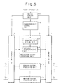
- Figure 8 is a diagram illustrating a construction of the first embodiment of the present invention.
- the construction of Fig. 8 corresponds to the same portion of a terminal station as Fig. 1.
- the same elements as Fig. 1 are denoted by the same reference numerals.
- reference numeral 22 1 to 22 N each denote a piece of working terminal equipment
- 23 denotes a piece of protection terminal equipment
- 24 denotes a control unit
- 26 1 to 26 N each denote a characteristic setting unit in each piece of working terminal equipment
- 28 1 to 28 N each denote a transmitter unit in each piece of working terminal equipment
- 27 denotes a characteristic setting unit in the piece of protection terminal equipment
- 29 denotes a protection-system transmitter unit in the piece of protection terminal equipment.
- Fig. 8 corresponds to the basic construction of Fig. 5.
- the control unit 24 realizes the functions of the switch control unit 5 and the characteristic control unit 8 in Fig. 5, and the pair of switch units 55 1 and 55 2 correspond to the pair of switch units 3 and 4 in Fig. 5, respectively.
- the pieces of working terminal equipment 22 1 to 22 N in Fig. 8 correspond to the working-system processing units 1 1 to 1 n in Fig. 5, respectively, and the piece of protection terminal equipment 23 in Fig. 8 corresponds to the protection-system processing unit 2 in Fig. 5.
- the characteristic setting unit 27 in the piece of protection terminal equipment 23 in Fig. 8 corresponds to the characteristic setting unit 7 in the protection-system processing unit 2 in Fig. 5, and the transmitter unit 29 in the piece of protection terminal equipment 23 in Fig. 8 corresponds to the variable-characteristic unit 6 in the protection-system processing unit 2 in Fig. 5.
- the transmitter units 28 1 to 28 N in the pieces of working terminal equipment 22 1 to 22 N have the same construction as the transmitter unit 29 in the piece of protection terminal equipment 23, and the pieces of working terminal equipment 22 1 to 22 N further contain the characteristic setting units 26 1 to 26 N , respectively.
- Each of the characteristic setting units 26 1 to 26 N and 27 in the pieces of working terminal equipment 22 1 to 22 N and the piece of protection terminal equipment 23 contains a register (as explained later with reference to Fig. 11) for holding control data (LBO 1 to LBO N ) for controlling the output characteristic of the corresponding transmitter unit.
- control data LBO 1 to LBO N
- the output characteristics of the transmitter units 28 1 to 28 N and 29 in the pieces of working terminal equipment 22 1 to 22 N and the piece of protection terminal equipment 23 are adjusted corresponding to the lengths of the tributary transmission lines 51 1 to 51 N (LINE BUILT OUT), and therefore the control data are denoted by LBO1 to LBON, respectively.
- Each of the transmitter units 28 1 to 28 N and 29 in the pieces of working terminal equipment 22 1 to 22 N and the piece of protection terminal equipment 23 has a construction such that the output characteristic thereof can be varied in accordance with the control data held in the above register in the corresponding characteristic setting unit. An example of such a construction of transmitter unit will be explained later with reference to Fig. 11.
- control data LBO 1 to LBO N may be preset in the above registers in the characteristic setting units 26 1 to 26 N by a manual switch (not shown) or by the control unit 24.
- the control unit 24 controls the switch units 55 1 and 55 2 so that the piece of protection terminal equipment 23, as a substitute for the above one of the plurality of pieces of working terminal equipment 22 1 to 22 N in which the alarm event has occurred, receives an input signal from one of the plurality of outputs of the demultiplexer 58 which corresponds to the substituted one of the plurality of pieces of working terminal equipment 22 1 to 22 N , and processes the input signal in accordance with a characteristic of the piece of protection terminal equipment 23, to output the processed signal to one of the plurality of tributary transmission lines 51 1 to 51 n which corresponds to the above substituted one of the plurality of pieces of working terminal equipment 22 1 to 22 N .
- the control unit 24 can set control data for use in controlling the transmitter unit 29 in the piece of protection terminal equipment 23, where the control data indicates a requested output characteristic of the transmitter unit 29 in the piece of protection terminal equipment 23.
- the control unit 24 sets the control data in the above-mentioned register in the characteristic setting unit 27 in the piece of protection terminal equipment 23, so that the output characteristic of the transmitter unit 29 in the piece of protection terminal equipment 23 becomes equivalent to the output characteristic of the above substituted one of the plurality of pieces of working terminal equipment 22 1 to 22 N .
- control unit 24 sets in the register in the characteristic setting unit 27 in the piece of protection terminal equipment 23, the same control data as that held in the register in the characteristic setting unit in the substituted one of the plurality of pieces of working terminal equipment 22 1 to 22 N .
- the transmitter unit 29 in the piece of protection terminal equipment 23 has the same output characteristic as the transmitter unit in the substituted one of the plurality of pieces of working terminal equipment 22 1 to 22N.
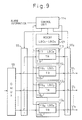
- Figure 9 is a diagram illustrating a construction of the second embodiment of the present invention.
- the construction of Fig. 9 corresponds to the same portion of a terminal station as Fig. 8.
- Fig. 9 the same elements as Fig. 8 are denoted by the same reference numerals.
- Fig. 9 the same elements as Fig. 8 are denoted by the same reference numerals.
- reference numeral 112 1 to 112 N each denote a piece of working terminal equipment
- 113 denotes a piece of protection terminal equipment
- 114 denotes a control unit
- 116 1 to 116 N each denote a characteristic setting unit in each piece of working terminal equipment
- 118 1 to 118 N each denote a transmitter unit in each piece of working terminal equipment
- 117 denotes a characteristic setting unit in the piece of protection terminal equipment
- 119 denotes a protection-system transmitter unit in the piece of protection terminal equipment.
- the construction of Fig. 9 further contains a memory 121 for storing control data (LBO 1 to LBO N ).
- Fig. 9 corresponds to the basic constructions of Figs. 6 and 7.
- the control unit 114 realizes the functions of the switch control unit 5 and the characteristic control unit 8 in Figs. 6 and 7, and the working characteristic reading unit 11 in Fig. 7, and the pair of switch units 55 1 and 55 2 correspond to the pair of switch units 3 and 4 in Figs. 6 and 7, respectively.
- the pieces of working terminal equipment 112 1 to 112 N in Fig. 9 correspond to the working-system processing units 1 1' to 1 n' in Fig. 7, respectively, and the piece of protection terminal equipment 113 in Fig. 9 corresponds to the protection-system processing unit 2 in Figs. 6 and 7.
- the characteristic setting unit 7 in the protection-system processing unit 2 in Figs. 6 and 7 corresponds to the characteristic setting unit 7 in the protection-system processing unit 2 in Figs. 6 and 7.
- the transmitter unit 119 in the piece of protection terminal equipment 113 in Fig. 9 corresponds to the variable-characteristic unit 6 in the protection-system processing unit 2 in Figs. 6 and 7.
- the characteristic setting units 116 1 to 116 N in Fig. 9 correspond to the characteristic setting units 10 1 to 10 n in Fig. 7, respectively
- the memory 121 in Fig. 9 corresponds to the working characteristic storing unit 9 in Fig. 7.
- control data LBO 1 to LBO N may be preset in the above registers in the characteristic setting units 116 1 to 116 N by a manual switch (not shown) or by the control unit 114.
- each of the pieces of working terminal equipment 112 1 to 112 N and the piece of protection terminal equipment 117 in Fig. 9 is the same as explained for the construction of Fig. 8, and the operations of controlling the switch units 55 1 and 55 2 , and setting of the control data in the characteristic setting unit 117 in the piece of protection terminal equipment 113, are performed in the same manner as the construction of Fig. 8.
- the memory 121 stores the control data which are the same as those held in the registers in the characteristic setting units 116 1 to 116 N in the pieces of working terminal equipment 112 1 to 112 N , and the control unit 114 can obtain the control data to be set in the characteristic setting unit 117 in the piece of protection terminal equipment 113, by referring to the memory 121.
- the control unit 124 can access the register in each of the characteristic setting units 116 1 to 116 N in the pieces of working terminal equipment 112 1 to 112 N , to read the content thereof. Therefore, the control unit 14 can obtain the above control data without referring to the memory 121. In addition, before starting the operation of the terminal station, the control unit 14 can obtain the control data held in the registers in the characteristic setting units 116 1 to 116 N in the respective pieces of working terminal equipment 112 1 to 112 N by accessing to them as above, and write the control data in the memory 121 for use in setting the control data in the characteristic setting unit 117 in the piece of protection terminal equipment 113 in operation.
- Figure 10 is a diagram illustrating a construction of the third embodiment of the present invention.
- the construction of Fig. 10 corresponds to the same portion of a terminal station as Figs. 8 and 9.
- Fig. 10 the same elements as Fig. 1 are denoted by the same reference numerals.
- Fig. 10 the same elements as Fig. 1 are denoted by the same reference numerals.
- reference numeral 132 1 to 132N each denote a piece of working terminal equipment
- 133 denotes a piece of protection terminal equipment
- 134 denotes a control unit
- 136 1 to 136 N each denote a characteristic setting unit in each piece of working terminal equipment
- 138 1 to 138 N each denote a transmitter unit in each piece of working terminal equipment
- 137 denotes a characteristic setting unit in the piece of protection terminal equipment 133
- 139 denotes a protection-system transmitter unit in the piece of protection terminal equipment 133.
- the characteristic setting unit 137 in the piece of protection terminal equipment 133 contains a plurality of working characteristic storing registers 141 1 to 141 N and a characteristic selector 142.
- the plurality of working characteristic storing registers 141 1 to 141 N are provided corresponding to the pieces of working terminal equipment 132 1 to 132 N , respectively.
- Each of the plurality of working characteristic storing registers 141 1 to 141 N stores control data which realizes in the transmitter unit 139 in the piece of protection terminal equipment 133 the output characteristic of the transmitter unit in one of the pieces of working terminal equipment 132 1 to 132 N corresponding to the working characteristic storing register.
- each of the plurality of working characteristic storing registers 141 1 to 141 N stores the same control data which is set in the characteristic setting unit in one of the pieces of working terminal equipment 132 1 to 132 N corresponding to the working characteristic storing register, when the transmitter units 138 1 to 138 N and 139 in the pieces of working terminal equipment 132 1 to 132 N and the piece of protection terminal equipment 133 have the same construction wherein the output characteristic thereof can be varied in accordance with the control data supplied from the corresponding characteristic setting unit.
- the characteristic selector 142 selects and applies to the transmitter unit 139 in the piece of protection terminal equipment 133, one of the outputs of the plurality of working characteristic storing registers 141 1 to 141 N corresponding to the substituted one of the plurality of pieces of working terminal equipment 132 1 to 132 N , where the control unit 134 controls the characteristic selector 142.
- control data realizing a requested characteristic in the transmitter unit 139 in the piece of protection terminal equipment 133 can be supplied to the transmitter unit 139.
- control data LBO 1 to LBO N may be preset in the above registers in the characteristic setting units 116 1 to 116 N by a manual switch (not shown) or by the control unit 114.
- control units 24, 114, and 134 may be performed by software or hardware logic circuitry.
- Figure 11 is a construction of an example of the variable-characteristic portion of each transmitter unit in the pieces of working and protection terminal equipment in the embodiments of Figs. 8, 9, and 10.
- the construction of the variable-characteristic portion indicated in Fig. 11 is provided in the final stage of each transmitter unit in the pieces of working and in the piece of protection terminal equipment.
- reference numeral 30 denotes a control data register which realizes the characteristic setting unit
- 31, 32, 33, and 34 each denote an analog switch
- 35 and 37 each denote a short-circuit path
- 36 and 38 each denote a filter circuit.
- the filter circuit 36 gives an amplitude loss and a phase shift which are equivalent to those a transmission line of a length equal to 100 feet gives, to transmission signals which pass through the filter circuit 36; and the filter circuit 37 gives an amplitude loss and a phase shift which are equivalent to those a transmission line of a length equal to 225 feet gives, to transmission signals which pass through the filter circuit 37.
- the control data register 30 contains four bits 30 1 , 30 2 , 30 3 , and 30 4 .
- the four bits 30 1 , 30 2 , 30 3 , and 30 4 controls the analog switches 31, 32, 33, and 34, respectively.
- transmission signals from the previous stage of the transmitter unit pass through the short-circuit paths 35 and 37, and are then output onto the tributary transmission line. Therefore, the transmission signals which are passed through the construction of Fig. 11 suffer an amplitude loss and a phase shift which are equivalent to those a transmission signal which is passed through a transmission line of a length equal to 100 feet suffers.
- the transmission signals which are passed through the construction of Fig. 11 suffer an amplitude loss and a phase shift which are equivalent to those a transmission signal which is passed through a transmission line of a length equal to 225 feet suffers.
- four bits 30 1 , 30 2 , 30 3 , and 30 4 are (1, 1, 1, 1)
- the transmission signals from the previous stage of the transmitter unit pass through the filter circuits 36 and 38, and are then output onto the tributary transmission line. Therefore, the transmission signals which are passed through the construction of Fig. 11 suffer an amplitude loss and a phase shift which are equivalent to those a transmission signal which is passed through a transmission line of a length equal to 325 feet suffers.
- the first and second switch units 55 1 and 55 2 may be constructed so that the connections in the first and second switch units 55 1 and 55 2 can be manually changed.
- the above operations for setting the control data by the control units in the respective embodiments may be triggerred by the detection of the change. Namely, when the control unit in each embodiment detects a change by which one of the plurality of pieces of working terminal equipment is substituted by the piece of protection terminal equipment, the control unit operates in the same way as in the case when the control unit receives the alarm information.
Landscapes
- Engineering & Computer Science (AREA)
- Computer Networks & Wireless Communication (AREA)
- Signal Processing (AREA)
- Transmitters (AREA)
- Mobile Radio Communication Systems (AREA)
Claims (4)
- Système pour traiter une pluralité de signaux en parallèle, comprenant :dans lequel ledit moyen de commande de caractéristique (8) commande le moyen de caractéristique variable (6) sur la base de l'information qui est stockée dans le moyen de stockage de caractéristique de travail (9).une pluralité d'unités de traitement de système de travail (11 à 1n) respectivement prévues de manière à correspondre à une pluralité de signaux d'entrée (121 à 12n), pour traiter un signal entré dessus et pour émettre en sortie le signal traité, où les unités de traitement de la pluralité d'unité de traitement de système de travail (11 à 1n) correspondent respectivement en outre à une pluralité de signaux de sortie (131 à 13n) ;une ou plusieurs unités de traitement de système de protection (2) pour traiter un signal entré dessus et pour émettre en sortie le signal traité ;un premier moyen de commutateur (3) pour recevoir et appliquer la pluralité de signaux d'entrée (121 à 12n) sur la pluralité correspondante d'unités de traitement de système de travail (11 à 1n), dans un premier mode, et pour respectivement recevoir et appliquer au moins l'un de la pluralité de signaux d'entrée (121 à 12n) sur au moins l'une desdites une ou plusieurs unités de traitement de système de protection (2) en tant qu'au moins un substitut de l'au moins une de la pluralité d'unités de traitement de système de travail (11 à 1n), dans un second mode ;un second moyen de commutateur (4) pour recevoir les signaux traités qui sont émis en sortie depuis la pluralité d'unités de traitement de système de travail (11 à 1n) et pour respectivement émettre en sortie les signaux traités en provenance de la pluralité d'unités de traitement de système de travail (11 à 1n), en tant que pluralité correspondante de signaux de sortie, dans le premier mode et pour recevoir au moins l'un des signaux traités émis en sortie depuis ladite au moins une desdites une ou plusieurs unités de traitement de système de protection (2) en tant que dit au moins un substitut de ladite au moins une de la pluralité d'unités de traitement de système de travail (11 à 1n) et pour émettre en sortie les signaux traités depuis ladite au moins une desdites une ou plusieurs unités de traitement de système de protection (2), en tant qu'au moins l'un de la pluralité de signaux de sortie (131 à 13n), de façon respective, dans le second mode ;un moyen de caractéristique variable (6) prévu dans chacune desdites une ou plusieurs unités de traitement de système de protection (2), pour faire varier une caractéristique de ladite chacune desdites une ou plusieurs unités de traitement de système de protection (2) ;un moyen de commande de caractéristique (8) pour commander le moyen de caractéristique variable (6) dans ledit au moins un desdits un ou plusieurs moyens de traitement de système de protection (2) de telle sorte que la caractéristique de ladite au moins une desdites une ou plusieurs unités de traitement de système de protection (2) devienne la même que la caractéristique de ladite au moins une de ladite pluralité d'unités de traitement de système de travail (11 à 1n) qui est ledit au moins un substitut de ladite au moins une desdites une ou plusieurs unités de traitement de système de protection (2) dans le second mode ;un moyen de stockage de caractéristique de travail (9) pour stocker une information concernant les caractéristiques de la pluralité d'unités de traitement de système de travail (11 à 1n),
- Système selon la revendication 1, dans lequel chacune de la pluralité d'unités de traitement de système de travail (11 à 1n) comprend un moyen de contenance d'information de caractéristique (101 à 10n) pour contenir une information indiquant la caractéristique de ladite chacune de la pluralité d'unités de traitement de système de travail (11 à 1n) ;
ledit système comprenant en outre un moyen de lecture de caractéristique de travail (11) pour lire une information concernant la caractéristique de chacune de la pluralité d'unités de traitement de système de travail (11 à 1n). - Système selon l'une quelconque des revendications 1 et 2, comprenant en outre un moyen d'établissement de caractéristique (7) pour contenir des données de commande dedans et pour appliquer les données de commande sur le moyen de caractéristique variable (6) ; et
ledit moyen de commande de caractéristique (8) commande le moyen de caractéristique variable (6) en établissant les données de commande dans le moyen d'établissement de caractéristique (7). - Système selon la revendication 3, dans lequel ledit moyen d'établissement de caractéristique (7) comprend :une pluralité de moyens de contenance de données de commande (1411 à 141N), prévus en correspondance avec la pluralité d'unités de traitement de système de travail (11 à 1n), chacun pour contenir et émettre en sortie les données de commande destinées à être établies dans le moyen d'établissement de caractéristique (7) dans l'une correspondante de la pluralité d'unités de traitement de système de travail (11 à 1n) lorsque le moyen de commande de caractéristique (8) commande le moyen de caractéristique variable (6) ; etun sélecteur (142) pour sélectionner les données de commande pour l'une de la pluralité d'unités de traitement de système de travail (11 à 1n) et pour appliquer les données de commande sélectionnées sur le moyen de caractéristique variable (6).
Applications Claiming Priority (3)
| Application Number | Priority Date | Filing Date | Title |
|---|---|---|---|
| JP5233104A JP2964207B2 (ja) | 1993-09-20 | 1993-09-20 | 現用予備切替制御方式 |
| JP233104/93 | 1993-09-20 | ||
| JP23310493 | 1993-09-20 |
Publications (3)
| Publication Number | Publication Date |
|---|---|
| EP0644664A2 EP0644664A2 (fr) | 1995-03-22 |
| EP0644664A3 EP0644664A3 (fr) | 1996-03-20 |
| EP0644664B1 true EP0644664B1 (fr) | 2001-12-19 |
Family
ID=16949841
Family Applications (1)
| Application Number | Title | Priority Date | Filing Date |
|---|---|---|---|
| EP94104428A Expired - Lifetime EP0644664B1 (fr) | 1993-09-20 | 1994-03-21 | Système pour adapter la caractéristique d'une unité de protection |
Country Status (4)
| Country | Link |
|---|---|
| US (1) | US5771225A (fr) |
| EP (1) | EP0644664B1 (fr) |
| JP (1) | JP2964207B2 (fr) |
| DE (1) | DE69429483T2 (fr) |
Families Citing this family (13)
| Publication number | Priority date | Publication date | Assignee | Title |
|---|---|---|---|---|
| JP2728066B2 (ja) * | 1995-12-07 | 1998-03-18 | 日本電気株式会社 | ユニット切替装置 |
| JP3745459B2 (ja) * | 1996-07-18 | 2006-02-15 | 富士通株式会社 | 無線lanシステム用通信方法及び通信装置 |
| US6327243B1 (en) * | 1998-08-03 | 2001-12-04 | Samsung Electronics Co., Ltd. | System and method for performing a seamless switchover from a primary packet router to a secondary packet router |
| US6925052B1 (en) | 1999-10-01 | 2005-08-02 | Agilent Technologies, Inc. | Multi-channel network monitoring apparatus, signal replicating device, and systems including such apparatus and devices, and enclosure for multi-processor equipment |
| GB2394849A (en) * | 1999-10-01 | 2004-05-05 | Agilent Technologies Inc | Multi-channel replicating device for broadband optical signals, and systems including such devices |
| US8018838B2 (en) * | 2002-06-25 | 2011-09-13 | Tellabs Operations, Inc. | Apparatus and method for protection switching in a network |
| KR100903217B1 (ko) * | 2007-08-30 | 2009-06-18 | 한국전자통신연구원 | 광 채널의 보호 절체 장치 및 방법 |
| US9002781B2 (en) | 2010-08-17 | 2015-04-07 | Fujitsu Limited | Annotating environmental data represented by characteristic functions |
| US8874607B2 (en) * | 2010-08-17 | 2014-10-28 | Fujitsu Limited | Representing sensor data as binary decision diagrams |
| US9138143B2 (en) | 2010-08-17 | 2015-09-22 | Fujitsu Limited | Annotating medical data represented by characteristic functions |
| US8930394B2 (en) * | 2010-08-17 | 2015-01-06 | Fujitsu Limited | Querying sensor data stored as binary decision diagrams |
| US9176819B2 (en) | 2011-09-23 | 2015-11-03 | Fujitsu Limited | Detecting sensor malfunctions using compression analysis of binary decision diagrams |
| US9075908B2 (en) | 2011-09-23 | 2015-07-07 | Fujitsu Limited | Partitioning medical binary decision diagrams for size optimization |
Family Cites Families (8)
| Publication number | Priority date | Publication date | Assignee | Title |
|---|---|---|---|---|
| US4245342A (en) * | 1979-01-10 | 1981-01-13 | Intech Laboratories, Inc. | One-for-n modem control apparatus |
| US4497054A (en) * | 1983-04-29 | 1985-01-29 | Honeywell Inc. | One-for-N redundancy in a digital switch matrix |
| JPS60194839A (ja) * | 1984-03-16 | 1985-10-03 | Fujitsu Ltd | 回線切替方式 |
| US4601028A (en) * | 1984-06-18 | 1986-07-15 | Rockwell International Corporation | Method of and apparatus for checking datapath failure in a communication muldem |
| JPS627226A (ja) * | 1985-07-04 | 1987-01-14 | Nec Corp | 共通予備切替方式 |
| JPS62253231A (ja) * | 1986-01-07 | 1987-11-05 | Fujitsu Ltd | 現用予備切換システム |
| DE69130148T2 (de) * | 1990-10-31 | 1999-01-28 | Nec Corp., Tokio/Tokyo | Synchrones Endstationssystem |
| JPH04259123A (ja) * | 1991-02-13 | 1992-09-14 | Nec Eng Ltd | 電力制御システム |
-
1993
- 1993-09-20 JP JP5233104A patent/JP2964207B2/ja not_active Expired - Fee Related
-
1994
- 1994-03-21 DE DE69429483T patent/DE69429483T2/de not_active Expired - Fee Related
- 1994-03-21 EP EP94104428A patent/EP0644664B1/fr not_active Expired - Lifetime
-
1996
- 1996-01-22 US US08/589,196 patent/US5771225A/en not_active Expired - Lifetime
Also Published As
| Publication number | Publication date |
|---|---|
| US5771225A (en) | 1998-06-23 |
| EP0644664A2 (fr) | 1995-03-22 |
| JP2964207B2 (ja) | 1999-10-18 |
| JPH0795131A (ja) | 1995-04-07 |
| DE69429483T2 (de) | 2002-07-18 |
| DE69429483D1 (de) | 2002-01-31 |
| EP0644664A3 (fr) | 1996-03-20 |
Similar Documents
| Publication | Publication Date | Title |
|---|---|---|
| EP0644664B1 (fr) | Système pour adapter la caractéristique d'une unité de protection | |
| US5216666A (en) | 1:n ring-type signal protection apparatus | |
| US5369642A (en) | Switcher for redundant signal transmission system | |
| US5495472A (en) | Methods and apparatus for utilizing protection paths as additional working paths in switched ring network systems | |
| US5406401A (en) | Apparatus and method for selective tributary switching in a bidirectional ring transmission system | |
| US4961190A (en) | (1+N) Hitless channel switching system | |
| JPH0637781A (ja) | リング・ノードと通信回路転送方法 | |
| US6560202B1 (en) | Control architecture using a multi-layer embedded signal status protocol | |
| US9060298B2 (en) | Distributed protection switching architecture for point-to-point microwave radio systems | |
| US6111853A (en) | Network protection scheme | |
| KR19990036711A (ko) | 삽입된 신호 상태 프로토콜을 이용하는 제어 아키텍쳐 | |
| US6002928A (en) | Switching apparatus and method for transceiver of cellular base station in code division multiple access mobile telecommunication system | |
| US6754172B1 (en) | Non-interruptive protection switching device and network system using the same | |
| EP1076432B1 (fr) | Système de télécommunication | |
| GB2390273A (en) | Network system incorporating protection paths in the transmission bandwidth of a virtual concatenation signal | |
| US5504856A (en) | Method and apparatus for controlling switching of transmission line | |
| US6418116B1 (en) | Transmission system having an uninterrupted switchover function for a plurality of lines | |
| JP2560617B2 (ja) | ホットスタンバイ送受信システム | |
| JPH1127181A (ja) | 予備回線への切替方式 | |
| JPH04334135A (ja) | 光ファイバプロテクション方式 | |
| JP2867865B2 (ja) | 予備回線切替制御方式 | |
| US6611409B1 (en) | Line module protection method and device utilizing said method | |
| JPS63197128A (ja) | 送信チヤネル切換装置 | |
| JP3044971B2 (ja) | 伝送装置の切替方式 | |
| JP3334868B2 (ja) | 同期光伝送装置 |
Legal Events
| Date | Code | Title | Description |
|---|---|---|---|
| PUAI | Public reference made under article 153(3) epc to a published international application that has entered the european phase |
Free format text: ORIGINAL CODE: 0009012 |
|
| AK | Designated contracting states |
Kind code of ref document: A2 Designated state(s): DE FR GB |
|
| PUAL | Search report despatched |
Free format text: ORIGINAL CODE: 0009013 |
|
| AK | Designated contracting states |
Kind code of ref document: A3 Designated state(s): DE FR GB |
|
| 17P | Request for examination filed |
Effective date: 19960920 |
|
| 17Q | First examination report despatched |
Effective date: 20000105 |
|
| GRAG | Despatch of communication of intention to grant |
Free format text: ORIGINAL CODE: EPIDOS AGRA |
|
| GRAG | Despatch of communication of intention to grant |
Free format text: ORIGINAL CODE: EPIDOS AGRA |
|
| GRAH | Despatch of communication of intention to grant a patent |
Free format text: ORIGINAL CODE: EPIDOS IGRA |
|
| GRAH | Despatch of communication of intention to grant a patent |
Free format text: ORIGINAL CODE: EPIDOS IGRA |
|
| GRAA | (expected) grant |
Free format text: ORIGINAL CODE: 0009210 |
|
| AK | Designated contracting states |
Kind code of ref document: B1 Designated state(s): DE FR GB |
|
| REG | Reference to a national code |
Ref country code: GB Ref legal event code: IF02 |
|
| REF | Corresponds to: |
Ref document number: 69429483 Country of ref document: DE Date of ref document: 20020131 |
|
| ET | Fr: translation filed | ||
| PLBE | No opposition filed within time limit |
Free format text: ORIGINAL CODE: 0009261 |
|
| STAA | Information on the status of an ep patent application or granted ep patent |
Free format text: STATUS: NO OPPOSITION FILED WITHIN TIME LIMIT |
|
| 26N | No opposition filed | ||
| PGFP | Annual fee paid to national office [announced via postgrant information from national office to epo] |
Ref country code: GB Payment date: 20080326 Year of fee payment: 15 |
|
| PGFP | Annual fee paid to national office [announced via postgrant information from national office to epo] |
Ref country code: FR Payment date: 20080311 Year of fee payment: 15 Ref country code: DE Payment date: 20080313 Year of fee payment: 15 |
|
| GBPC | Gb: european patent ceased through non-payment of renewal fee |
Effective date: 20090321 |
|
| REG | Reference to a national code |
Ref country code: FR Ref legal event code: ST Effective date: 20091130 |
|
| PG25 | Lapsed in a contracting state [announced via postgrant information from national office to epo] |
Ref country code: DE Free format text: LAPSE BECAUSE OF NON-PAYMENT OF DUE FEES Effective date: 20091001 |
|
| PG25 | Lapsed in a contracting state [announced via postgrant information from national office to epo] |
Ref country code: GB Free format text: LAPSE BECAUSE OF NON-PAYMENT OF DUE FEES Effective date: 20090321 Ref country code: FR Free format text: LAPSE BECAUSE OF NON-PAYMENT OF DUE FEES Effective date: 20091123 |