EP0645219B1 - Clamping device for an elongated piece - Google Patents
Clamping device for an elongated piece Download PDFInfo
- Publication number
- EP0645219B1 EP0645219B1 EP94104726A EP94104726A EP0645219B1 EP 0645219 B1 EP0645219 B1 EP 0645219B1 EP 94104726 A EP94104726 A EP 94104726A EP 94104726 A EP94104726 A EP 94104726A EP 0645219 B1 EP0645219 B1 EP 0645219B1
- Authority
- EP
- European Patent Office
- Prior art keywords
- unit
- clamping device
- guide
- sheave
- wheel portions
- Prior art date
- Legal status (The legal status is an assumption and is not a legal conclusion. Google has not performed a legal analysis and makes no representation as to the accuracy of the status listed.)
- Expired - Lifetime
Links
- 238000010276 construction Methods 0.000 claims description 6
- 230000005484 gravity Effects 0.000 claims description 5
- 244000007853 Sarothamnus scoparius Species 0.000 description 12
- XLYOFNOQVPJJNP-UHFFFAOYSA-N water Substances O XLYOFNOQVPJJNP-UHFFFAOYSA-N 0.000 description 2
- 230000000712 assembly Effects 0.000 description 1
- 238000000429 assembly Methods 0.000 description 1
- 230000000903 blocking effect Effects 0.000 description 1
- 230000007812 deficiency Effects 0.000 description 1
Images



Classifications
-
- B—PERFORMING OPERATIONS; TRANSPORTING
- B25—HAND TOOLS; PORTABLE POWER-DRIVEN TOOLS; MANIPULATORS
- B25H—WORKSHOP EQUIPMENT, e.g. FOR MARKING-OUT WORK; STORAGE MEANS FOR WORKSHOPS
- B25H3/00—Storage means or arrangements for workshops facilitating access to, or handling of, work tools or instruments
- B25H3/04—Racks
-
- A—HUMAN NECESSITIES
- A47—FURNITURE; DOMESTIC ARTICLES OR APPLIANCES; COFFEE MILLS; SPICE MILLS; SUCTION CLEANERS IN GENERAL
- A47L—DOMESTIC WASHING OR CLEANING; SUCTION CLEANERS IN GENERAL
- A47L13/00—Implements for cleaning floors, carpets, furniture, walls, or wall coverings
- A47L13/10—Scrubbing; Scouring; Cleaning; Polishing
- A47L13/50—Auxiliary implements
- A47L13/51—Storing of cleaning tools, e.g. containers therefor
- A47L13/512—Clamping devices for hanging the tools
-
- A—HUMAN NECESSITIES
- A63—SPORTS; GAMES; AMUSEMENTS
- A63C—SKATES; SKIS; ROLLER SKATES; DESIGN OR LAYOUT OF COURTS, RINKS OR THE LIKE
- A63C11/00—Accessories for skiing or snowboarding
- A63C11/02—Devices for stretching, clamping or pressing skis or snowboards for transportation or storage
- A63C11/028—Storage in cupboards or ski-racks, e.g. with clamping devices
Definitions
- This invention relates to a clamping device for an elongated piece, more particularly to a clamping device for clamping steadily an elongated piece as defined in the preambles of claims 1 and 10.
- Such clamping devices are known from the document US-Patent No. 3 422 960.
- a conventional clamping device generally comprises a stationary unit, a guide unit spaced apart from the stationary unit at a predetermined distance, a movable unit movably mounted on the guide unit and a bias unit interconnecting the guide unit and the movable unit so as to bias the movable unit to move toward the stationary unit so as to hold an elongated piece between the stationary unit and the movable unit, wherein the guide unit comprises a guide block and a rack member mounted on a top surface of the guide block (US-Patent No. 3 422 960).
- the force exerted by the bias unit is insufficient to effectively clamp an elongated piece between the movable unit and the stationary unit or it may require two hand operation which is to some extent inconvenience.
- the main objective of this invention is to provide a clamping device for clamping steadily an elongated piece which overcomes the deficiencies of the prior art.
- a clamping device in accordance with an aspect of the present invention is characterized by the features specified in the characterizing part of claim 1 and a clamping device in accordance with another aspect of the present invention is characterized by the features specified in the characterizing part of claim 10.
- the movable unit comprises a sheave which has two wheel portions and a pinion portion that is located between the wheel portions and that engages the rack member so as to guide the wheel portions of the sheave to move on the guide block.
- the bias unit interconnects the guide unit and the movable unit so as to bias the wheel portions of the sheave to move toward the stationary unit, thereby holding an elongated piece between the sheave and the stationary unit.
- a clamping device comprises two spaced guide units, two movable units and two bias units.
- Each of the guide units comprises a guide block and a rack member which is secured on the top surface of the guide block.
- Each of the movable units comprises a sheave which has two wheel portions and a pinion portions that is located between the wheel portions and that engages a respective one of the rack members so as to guide the sheaves to move on the guide units.
- Each of the bias units interconnects one of the guide units and one of the movable units so as to bias the movable units to move toward each other, thereby holding an elongated piece between the movable units.
- the stationary shell body 13 has a vertical side wall 131, an L-shaped top wall 1311 extending from the rear portion of the top end of the vertical side wall 131 to define a groove 137 between the side wall 131 and the top wall 1311, a horizontal top wall 1321 extending from the front portion of the top end of the vertical side wall 131 and a horizontal bottom wall 1322 extending from the front portion of the bottom end of the vertical side wall 131.
- a recess 136 is formed in the shell body 13 between the top and bottom walls 1321, 1322.
- a vertical positioning plate 138 interconnects the top and bottom walls 1321, 1322 and is made of rubber so as to provide a frictional clamping surface.
- the stationary unit 14 has a frictional clamping surface which is similar to that of the vertical positioning plate 138 in construction.
- the guide unit comprises a guide block 11 which is confined in the recess 136 by a blocking plate 134 and which has an inclined flat top surface 111 and a rack member 112 secured to the inclined flat top surface 111.
- the sheave 12 has two wheel portions 122 and a pinion portion 121 that is located between the wheel portions 122 and that engages the rack member 112.
- the inclined flat top surface 111 of the guide block 11 functions as biasing means for biasing and thus having the sheave 12 automatically move toward the stationary unit 14 by virtue of gravity.
- the wheel portions 122 are made of rubber so as to provide frictional clamping surfaces. Accordingly, when the sheave 12 moves toward the stationary unit 14, the wheel portions 122 of the sheave 12 can protrude out of the recess 136 of the shell body 13 so as to define a clamping space 15 (see Fig.
- the shell body 13 further comprises a block member 135 secured to the lower end portion of the vertical side wall 131 near the recess 136 so as to prevent disengagement of the wheel portions 122 from the recess 136, as shown in Fig. 3.
- the sheave 12 and the guide unit together constitute a clamping unit pair for cooperatively clamping therebetween a slender article.
- the clamping device further comprises a positioning plate 8 which may be secured to a wall by means of screws (not shown) that extend through holes 81 thereof.
- the positioning-plate 8 has an L-shaped guide flange 82 that projects from the top end of the positioning plate 8 so as to extend into the groove 137 of the shell body 13 and a support plate 84 that projects from the bottom end of the positioning plate 8 so as to support the vertical side wall 131 thereon so as to fix the shell body 13 on the positioning plate 8 by means of screws (not shown) that extend through holes 83.
- one of the wheel portions 122 of the sheave 12 presses against the block member 135 so as to be stopped there to prevent the disengagement of the sheave 12 from the shell body 13.
- the vertical rod portion of the broom 9 must be extended upward through clamping space 15 so as to push the sheave 12 to roll upward along the rack member 112 of the guide block 11.
- the sheave 12 moves toward the vertical positioning plate 138 by virtue of gravity so that the wheel portion 112 and the vertical positioning plate 138 press against the vertical rod portion of the broom 9.
- the broom 9 When it is desired to remove the broom 9 from the clamping space 15, the broom 9 is pushed upward so that the wheel portions 122 of the sheave 12 can roll upward along the rack member 112 due to the frictional force between the vertical rod portion of the broom 9 and the wheel portions 122 of the sheave 12, thereby permitting removal of the broom 9 from the clamping space 15.
- Fig. 6 illustrates an application of the clamping device of the first embodiment of the present invention.
- a plurality of the clamping devices (only three are shown) are arranged in a row in such a manner that the shell bodies 13 are mounted on the positioning plate 8 and that in any adjacent pairs of the shell bodies 13, the recess 136 of one of the shell bodies 13 faces the vertical positioning plate 138 of the other one of the shell bodies 13, thereby defining three clamping spaces 15 therebetween.
- Fig. 7 illustrates another application of the clamping device of the first embodiment of the present invention. As illustrated, there are a plurality of pairs of clamping devices (only three pairs are shown) arranged in a row in such a manner that the vertical side wall 131 of each pair of the clamping devices abut against each other so as to define two rows of clamping spaces 15 therebetween.
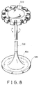
- Fig. 8 illustrates a further application of the first embodiment of the present invention.
- a plurality of clamping devices of the present invention are mounted to a slender stand 500.
- the slender stand 500 has a disk member 510 mounted on the top end thereof with the clamping devices of the present invention secured to the circumference thereof for holding thereon slender articles, such as the handle of brooms or mops.
- the stand 500 has an expanded base 520 mounted on the bottom end thereof for soundly support the stand 500 on ground.
- the base 520 has a recess 530 formed thereon to serve as a water container for receiving therein water droplets from for example wet mops that are held by the clamping devices of the present invention.
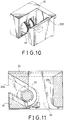
- the clamping device of the second embodiment of the present invention which comprises a stationary unit 24, a stationary shell body 23, a sheave 22 and a guide block 21.
- the stationary unit 24, the shell body 23 and the sheave 22 are similar to those of the first embodiment in construction.
- the guide block 21 has a horizontal top surface on which a rack member lies and a spring element 214 which interconnects the vertical positioning plate 238 of the shell body 23 and the sheave 22 so as to bias the sheave 22 toward the stationary unit 24.
- the clamping device of the third embodiment of the present invention which comprises a guide block 31, a sheave 32 and a stationary shell body 33.
- the guide block 31 and the sheave 32 are similar to those of the first embodiment in construction.
- the shell body 33 has a recess 336 defined therein so as to confine the guide block 31 and the sheave 32 therein and a vertical positioning plate 335 which is secured to the shell body 33 and which is spaced apart from the recess 336 of the shell body 33 at a predetermined distance so as to serve as a stationary unit, thereby defining a clamping space 35 between the recess 336 of the shell body 33 and the vertical positioning plate 335.
- the vertical positioning plate 335 has a frictional clamping surface so as to hold steadily an elongated piece in the clamping space 35.
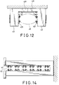
- the clamping device of the fourth embodiment of the present invention which comprises two generally L-shaped stationary shell bodies 43 spaced apart from each other at a predetermined distance, two guide units respectively confined within the shell bodies 43 and two movable units respectively and movably mounted on the guide units.
- Each of the shell bodies 43 is similar to that of the first embodiment is construction and has a vertical side wall 431 secured to a wall.
- Each of the vertical side walls 431 of the shell bodies 43 has a vertical end surface. The vertical end surfaces abut against each other so as to form a clamping space 45 between the shell bodies 43.
- Each of the guide units comprises a guide block 41 confined within the recess 436 of the corresponding one of the shell bodies 43.
- Each of the guide blocks 41 has an inclined flat top surface 411 and a rack member 412 secured to the inclined flat top surface 411.
- Each of the movable units comprises a sheave 42 which is similar to that of the first embodiment in construction and is engageable with the rack member 412 of the respective one of the guide blocks 41, thereby guiding the sheaves 42 to move toward each other.
- each of the wheel portions 421 of the sheaves 42 protrude out of the recess 436 of the corresponding one of the shell bodies 43 so as to hold an elongated piece 90 between the wheel portions 421 of the sheaves 42.
- each of the wheel portions 421 of the sheaves 42 has a frictional clamping surface so as to hold steadily the elongated piece 90 in the clamping space 45.
- Fig. 14 illustrates an application of the fourth embodiment of the clamping device of the present invention. As illustrated, there are six clamping devices arranged in a row so as to define six clamping spaces 45 between the sheaves 42 of the clamping devices.
Landscapes
- Engineering & Computer Science (AREA)
- Mechanical Engineering (AREA)
- Clamps And Clips (AREA)
- Advancing Webs (AREA)
- Adornments (AREA)
- Prostheses (AREA)
- Supports Or Holders For Household Use (AREA)
- Escalators And Moving Walkways (AREA)
- Sewing Machines And Sewing (AREA)
- Chain Conveyers (AREA)
- Transmission Devices (AREA)
Applications Claiming Priority (4)
| Application Number | Priority Date | Filing Date | Title |
|---|---|---|---|
| GB9317590A GB2281338B (en) | 1993-08-24 | 1993-08-24 | Clamping device for an elongated piece |
| CA002105505A CA2105505C (en) | 1993-08-24 | 1993-09-03 | Clamping device for an elongated piece |
| US08/127,312 US5342010A (en) | 1993-08-24 | 1993-09-27 | Clamping device for an elongated piece |
| US127312 | 1993-09-27 |
Publications (2)
| Publication Number | Publication Date |
|---|---|
| EP0645219A1 EP0645219A1 (en) | 1995-03-29 |
| EP0645219B1 true EP0645219B1 (en) | 1997-09-24 |
Family
ID=27169575
Family Applications (1)
| Application Number | Title | Priority Date | Filing Date |
|---|---|---|---|
| EP94104726A Expired - Lifetime EP0645219B1 (en) | 1993-08-24 | 1994-03-24 | Clamping device for an elongated piece |
Country Status (11)
| Country | Link |
|---|---|
| US (1) | US5342010A (da) |
| EP (1) | EP0645219B1 (da) |
| AT (1) | ATE158533T1 (da) |
| AU (1) | AU661224B2 (da) |
| CA (1) | CA2105505C (da) |
| DK (1) | DK0645219T3 (da) |
| ES (1) | ES2109534T3 (da) |
| GB (1) | GB2281338B (da) |
| GR (1) | GR3025707T3 (da) |
| NZ (1) | NZ260001A (da) |
| RU (1) | RU2087117C1 (da) |
Families Citing this family (16)
| Publication number | Priority date | Publication date | Assignee | Title |
|---|---|---|---|---|
| FR2758064A1 (fr) * | 1997-01-07 | 1998-07-10 | Danet Jean Francois | Systeme de presentation verticale de pieces planes au moyen de boules dans un logement trapezoidal |
| GB2355041B (en) * | 1999-10-07 | 2001-09-05 | Chntuo Ind Co Ltd | Securing device |
| US6435357B1 (en) * | 2001-04-16 | 2002-08-20 | Ming-Hui Lee | Tool holding device |
| US6595376B1 (en) * | 2002-03-08 | 2003-07-22 | Joseph Jui-Chin Lin | Clamp device for holding tool with shank |
| FR2850728A1 (fr) * | 2003-02-04 | 2004-08-06 | Hygien Or | Dispositif de maintien d'objets sur un plateau de groupage de ces objets |
| US20060032828A1 (en) * | 2004-05-29 | 2006-02-16 | Chiu Sai Y | Holder for organization and storage |
| US7445129B2 (en) * | 2004-09-21 | 2008-11-04 | Jui-Chin Lin | Holding device for holding tubular items |
| US20060060546A1 (en) * | 2004-09-21 | 2006-03-23 | Jui-Chin Lin | Holding device for holding tubular items |
| US20060208138A1 (en) * | 2005-03-18 | 2006-09-21 | Usun Technology Co., Ltd. | [rod member holder] |
| US20090044478A1 (en) * | 2007-08-13 | 2009-02-19 | Jones Yeh | Clamping Structure |
| TWM347787U (en) * | 2008-05-02 | 2008-12-21 | Wistron Corp | A fixture structure of a handheld electronic device |
| USD617989S1 (en) | 2009-03-20 | 2010-06-22 | Helen Of Troy Limited | Organizer |
| RU2405671C1 (ru) * | 2009-10-26 | 2010-12-10 | Федеральное государственное образовательное учреждение высшего профессионального образования Сибирский федеральный университет (СФУ) | Устройство для хранения и выдачи инструмента |
| US9095975B2 (en) * | 2013-06-26 | 2015-08-04 | RB Distribution, Inc. | Tool holder with rolling grip |
| CN108621051B (zh) * | 2018-05-09 | 2020-06-19 | 安徽瑞林精科股份有限公司 | 一种便于使用的机油泵传动轴支架用夹具 |
| CN113864130B (zh) * | 2021-08-31 | 2024-01-26 | 江西大唐国际新能源有限公司 | 一种风力发电叶片用夹持设备 |
Family Cites Families (14)
| Publication number | Priority date | Publication date | Assignee | Title |
|---|---|---|---|---|
| US588030A (en) * | 1897-08-10 | Broom-holder | ||
| US1485092A (en) * | 1923-06-23 | 1924-02-26 | Frank J Rauchut | Broom and mop holder |
| US1494252A (en) * | 1923-12-13 | 1924-05-13 | Kane James | Article holder |
| US1674581A (en) * | 1927-08-11 | 1928-06-19 | Alton J Webb | Broom holder |
| US2370876A (en) * | 1944-01-29 | 1945-03-06 | Presly C Richardson | Hanger for slender articles |
| US2869209A (en) * | 1957-07-31 | 1959-01-20 | Kautzky Joe | Rod holding device |
| US3422960A (en) * | 1965-10-10 | 1969-01-21 | Fredrick James Ell | Gear and rack tool holder |
| US3294350A (en) * | 1965-11-30 | 1966-12-27 | Grottola Oresto | Article holder |
| CH597807A5 (da) * | 1975-09-26 | 1978-04-14 | Wolf Geraete Gmbh | |
| DE2739595A1 (de) * | 1977-08-31 | 1979-03-08 | Johannes Breiting | Wandhalterung fuer gebrauchsgegenstaende zur verwendung insbesondere in badezimmern |
| JPS6189506U (da) * | 1984-11-19 | 1986-06-11 | ||
| CH674881A5 (en) * | 1988-01-26 | 1990-07-31 | Fehlbaum & Co | Support arm and plate suspended from tubular column - has clamp with two holders on plate either side, secured by bolt |
| EP0388570A1 (fr) * | 1989-03-22 | 1990-09-26 | John Green | Dispositif d'auto-serrage |
| US5165629A (en) * | 1991-07-10 | 1992-11-24 | Geerpres, Inc. | Adjustable tool holder assembly |
-
1993
- 1993-08-24 GB GB9317590A patent/GB2281338B/en not_active Expired - Fee Related
- 1993-09-03 CA CA002105505A patent/CA2105505C/en not_active Expired - Lifetime
- 1993-09-27 US US08/127,312 patent/US5342010A/en not_active Expired - Lifetime
-
1994
- 1994-03-01 NZ NZ260001A patent/NZ260001A/en unknown
- 1994-03-01 AU AU56484/94A patent/AU661224B2/en not_active Ceased
- 1994-03-04 RU RU9494007082A patent/RU2087117C1/ru active
- 1994-03-24 ES ES94104726T patent/ES2109534T3/es not_active Expired - Lifetime
- 1994-03-24 DK DK94104726.8T patent/DK0645219T3/da active
- 1994-03-24 EP EP94104726A patent/EP0645219B1/en not_active Expired - Lifetime
- 1994-03-24 AT AT94104726T patent/ATE158533T1/de not_active IP Right Cessation
-
1997
- 1997-12-17 GR GR970403358T patent/GR3025707T3/el unknown
Also Published As
| Publication number | Publication date |
|---|---|
| AU661224B2 (en) | 1995-07-13 |
| NZ260001A (en) | 1995-07-26 |
| GR3025707T3 (en) | 1998-03-31 |
| GB2281338A (en) | 1995-03-01 |
| ES2109534T3 (es) | 1998-01-16 |
| AU5648494A (en) | 1995-04-27 |
| US5342010A (en) | 1994-08-30 |
| CA2105505A1 (en) | 1995-03-04 |
| EP0645219A1 (en) | 1995-03-29 |
| GB9317590D0 (en) | 1993-10-06 |
| ATE158533T1 (de) | 1997-10-15 |
| RU2087117C1 (ru) | 1997-08-20 |
| CA2105505C (en) | 1999-12-21 |
| DK0645219T3 (da) | 1998-05-04 |
| GB2281338B (en) | 1996-08-21 |
Similar Documents
| Publication | Publication Date | Title |
|---|---|---|
| EP0645219B1 (en) | Clamping device for an elongated piece | |
| US6386363B1 (en) | Compact tool holder and display system | |
| US4310094A (en) | Tool rack | |
| US6435357B1 (en) | Tool holding device | |
| US4941784A (en) | Device for stabilizing objects within the trunk of a vehicle | |
| US5598924A (en) | Spanner holder | |
| US4654989A (en) | Vertical three-dimensional image screen | |
| US5513758A (en) | Tool holder | |
| CA2011608A1 (en) | Holder for socket wrench heads | |
| US4614273A (en) | Free stop retainer | |
| US5544396A (en) | Holder for securing objects | |
| US5931299A (en) | Toolholder | |
| US2639815A (en) | Tool rack | |
| JPH0532138B2 (da) | ||
| US6039178A (en) | Organizer for a set of hand tools | |
| CA2030223C (en) | Holder for tape cartridges | |
| US3412846A (en) | Coin holder | |
| US5713440A (en) | Positioning and ejecting device for a retractable handle | |
| US4971199A (en) | Holder for tape cartridges | |
| KR200446630Y1 (ko) | 하드디스크 드라이버 트레이 | |
| US3450269A (en) | Toothbrush holder | |
| KR860001717B1 (ko) | 프리스톱 수구(受具) | |
| US5584400A (en) | Adjustable lens rack | |
| US5470168A (en) | Device for speedily mounting objects on tubes and bars | |
| CN219782403U (zh) | 一种砧板架 |
Legal Events
| Date | Code | Title | Description |
|---|---|---|---|
| PUAI | Public reference made under article 153(3) epc to a published international application that has entered the european phase |
Free format text: ORIGINAL CODE: 0009012 |
|
| AK | Designated contracting states |
Kind code of ref document: A1 Designated state(s): AT BE CH DK ES FR GR IE IT LI LU MC NL PT SE |
|
| 17P | Request for examination filed |
Effective date: 19950817 |
|
| 17Q | First examination report despatched |
Effective date: 19960417 |
|
| GRAG | Despatch of communication of intention to grant |
Free format text: ORIGINAL CODE: EPIDOS AGRA |
|
| GRAH | Despatch of communication of intention to grant a patent |
Free format text: ORIGINAL CODE: EPIDOS IGRA |
|
| GRAH | Despatch of communication of intention to grant a patent |
Free format text: ORIGINAL CODE: EPIDOS IGRA |
|
| GRAA | (expected) grant |
Free format text: ORIGINAL CODE: 0009210 |
|
| AK | Designated contracting states |
Kind code of ref document: B1 Designated state(s): AT BE CH DK ES FR GR IE IT LI LU MC NL PT SE |
|
| REF | Corresponds to: |
Ref document number: 158533 Country of ref document: AT Date of ref document: 19971015 Kind code of ref document: T |
|
| REG | Reference to a national code |
Ref country code: CH Ref legal event code: EP |
|
| ITF | It: translation for a ep patent filed | ||
| REG | Reference to a national code |
Ref country code: CH Ref legal event code: NV Representative=s name: HUG INTERLIZENZ AG |
|
| REG | Reference to a national code |
Ref country code: ES Ref legal event code: FG2A Ref document number: 2109534 Country of ref document: ES Kind code of ref document: T3 |
|
| ET | Fr: translation filed | ||
| REG | Reference to a national code |
Ref country code: IE Ref legal event code: FG4D Free format text: 76681 |
|
| REG | Reference to a national code |
Ref country code: PT Ref legal event code: SC4A Free format text: AVAILABILITY OF NATIONAL TRANSLATION Effective date: 19971212 |
|
| REG | Reference to a national code |
Ref country code: DK Ref legal event code: T3 |
|
| PLBE | No opposition filed within time limit |
Free format text: ORIGINAL CODE: 0009261 |
|
| STAA | Information on the status of an ep patent application or granted ep patent |
Free format text: STATUS: NO OPPOSITION FILED WITHIN TIME LIMIT |
|
| 26N | No opposition filed | ||
| PGFP | Annual fee paid to national office [announced via postgrant information from national office to epo] |
Ref country code: PT Payment date: 20020226 Year of fee payment: 9 |
|
| PGFP | Annual fee paid to national office [announced via postgrant information from national office to epo] |
Ref country code: NL Payment date: 20020318 Year of fee payment: 9 Ref country code: FR Payment date: 20020318 Year of fee payment: 9 |
|
| PGFP | Annual fee paid to national office [announced via postgrant information from national office to epo] |
Ref country code: DK Payment date: 20020322 Year of fee payment: 9 Ref country code: IE Payment date: 20020322 Year of fee payment: 9 Ref country code: AT Payment date: 20020322 Year of fee payment: 9 |
|
| PGFP | Annual fee paid to national office [announced via postgrant information from national office to epo] |
Ref country code: ES Payment date: 20020325 Year of fee payment: 9 Ref country code: SE Payment date: 20020325 Year of fee payment: 9 Ref country code: LU Payment date: 20020325 Year of fee payment: 9 Ref country code: CH Payment date: 20020325 Year of fee payment: 9 Ref country code: BE Payment date: 20020325 Year of fee payment: 9 |
|
| PGFP | Annual fee paid to national office [announced via postgrant information from national office to epo] |
Ref country code: MC Payment date: 20020327 Year of fee payment: 9 |
|
| PGFP | Annual fee paid to national office [announced via postgrant information from national office to epo] |
Ref country code: GR Payment date: 20020329 Year of fee payment: 9 |
|
| PG25 | Lapsed in a contracting state [announced via postgrant information from national office to epo] |
Ref country code: LU Free format text: LAPSE BECAUSE OF NON-PAYMENT OF DUE FEES Effective date: 20030324 Ref country code: IE Free format text: LAPSE BECAUSE OF NON-PAYMENT OF DUE FEES Effective date: 20030324 Ref country code: AT Free format text: LAPSE BECAUSE OF NON-PAYMENT OF DUE FEES Effective date: 20030324 |
|
| PG25 | Lapsed in a contracting state [announced via postgrant information from national office to epo] |
Ref country code: SE Free format text: LAPSE BECAUSE OF NON-PAYMENT OF DUE FEES Effective date: 20030325 Ref country code: ES Free format text: LAPSE BECAUSE OF NON-PAYMENT OF DUE FEES Effective date: 20030325 |
|
| PG25 | Lapsed in a contracting state [announced via postgrant information from national office to epo] |
Ref country code: MC Free format text: LAPSE BECAUSE OF NON-PAYMENT OF DUE FEES Effective date: 20030331 Ref country code: LI Free format text: LAPSE BECAUSE OF NON-PAYMENT OF DUE FEES Effective date: 20030331 Ref country code: DK Free format text: LAPSE BECAUSE OF NON-PAYMENT OF DUE FEES Effective date: 20030331 Ref country code: CH Free format text: LAPSE BECAUSE OF NON-PAYMENT OF DUE FEES Effective date: 20030331 Ref country code: BE Free format text: LAPSE BECAUSE OF NON-PAYMENT OF DUE FEES Effective date: 20030331 |
|
| BERE | Be: lapsed |
Owner name: *YAMCHEN INDUSTRIAL CO. LTD Effective date: 20030331 |
|
| PG25 | Lapsed in a contracting state [announced via postgrant information from national office to epo] |
Ref country code: PT Free format text: LAPSE BECAUSE OF NON-PAYMENT OF DUE FEES Effective date: 20030930 |
|
| PG25 | Lapsed in a contracting state [announced via postgrant information from national office to epo] |
Ref country code: NL Free format text: LAPSE BECAUSE OF NON-PAYMENT OF DUE FEES Effective date: 20031001 |
|
| PG25 | Lapsed in a contracting state [announced via postgrant information from national office to epo] |
Ref country code: GR Free format text: LAPSE BECAUSE OF NON-PAYMENT OF DUE FEES Effective date: 20031002 |
|
| EUG | Se: european patent has lapsed | ||
| REG | Reference to a national code |
Ref country code: CH Ref legal event code: PL |
|
| PG25 | Lapsed in a contracting state [announced via postgrant information from national office to epo] |
Ref country code: FR Free format text: LAPSE BECAUSE OF NON-PAYMENT OF DUE FEES Effective date: 20031127 |
|
| NLV4 | Nl: lapsed or anulled due to non-payment of the annual fee |
Effective date: 20031001 |
|
| REG | Reference to a national code |
Ref country code: PT Ref legal event code: MM4A Free format text: LAPSE DUE TO NON-PAYMENT OF FEES Effective date: 20030930 |
|
| REG | Reference to a national code |
Ref country code: FR Ref legal event code: ST |
|
| REG | Reference to a national code |
Ref country code: IE Ref legal event code: MM4A |
|
| REG | Reference to a national code |
Ref country code: ES Ref legal event code: FD2A Effective date: 20030325 |
|
| PG25 | Lapsed in a contracting state [announced via postgrant information from national office to epo] |
Ref country code: IT Free format text: LAPSE BECAUSE OF NON-PAYMENT OF DUE FEES;WARNING: LAPSES OF ITALIAN PATENTS WITH EFFECTIVE DATE BEFORE 2007 MAY HAVE OCCURRED AT ANY TIME BEFORE 2007. THE CORRECT EFFECTIVE DATE MAY BE DIFFERENT FROM THE ONE RECORDED. Effective date: 20050324 |