EP0645261A1 - Vorrichtung für die Fertigung von aus klebegebundenen Druckbogen gebildeten Buchblöcken - Google Patents
Vorrichtung für die Fertigung von aus klebegebundenen Druckbogen gebildeten Buchblöcken Download PDFInfo
- Publication number
- EP0645261A1 EP0645261A1 EP94810526A EP94810526A EP0645261A1 EP 0645261 A1 EP0645261 A1 EP 0645261A1 EP 94810526 A EP94810526 A EP 94810526A EP 94810526 A EP94810526 A EP 94810526A EP 0645261 A1 EP0645261 A1 EP 0645261A1
- Authority
- EP
- European Patent Office
- Prior art keywords
- printed sheets
- support element
- guide rail
- bristles
- stack
- Prior art date
- Legal status (The legal status is an assumption and is not a legal conclusion. Google has not performed a legal analysis and makes no representation as to the accuracy of the status listed.)
- Granted
Links
- 238000004519 manufacturing process Methods 0.000 title claims abstract description 5
- 238000004804 winding Methods 0.000 claims description 5
- 239000000853 adhesive Substances 0.000 claims description 3
- 230000001070 adhesive effect Effects 0.000 claims description 3
- 230000000149 penetrating effect Effects 0.000 claims description 2
- 241000904500 Oxyspora paniculata Species 0.000 description 1
- 239000011230 binding agent Substances 0.000 description 1
- 230000015572 biosynthetic process Effects 0.000 description 1
- 230000006835 compression Effects 0.000 description 1
- 238000007906 compression Methods 0.000 description 1
- 230000006735 deficit Effects 0.000 description 1
- 230000000694 effects Effects 0.000 description 1
- 230000002349 favourable effect Effects 0.000 description 1
- 239000000945 filler Substances 0.000 description 1
- 230000001771 impaired effect Effects 0.000 description 1
- 238000000034 method Methods 0.000 description 1
- 230000000717 retained effect Effects 0.000 description 1
- 238000005096 rolling process Methods 0.000 description 1
- 230000002393 scratching effect Effects 0.000 description 1
- 239000013589 supplement Substances 0.000 description 1
Images
Classifications
-
- B—PERFORMING OPERATIONS; TRANSPORTING
- B42—BOOKBINDING; ALBUMS; FILES; SPECIAL PRINTED MATTER
- B42C—BOOKBINDING
- B42C19/00—Multi-step processes for making books
- B42C19/08—Conveying between operating stations in machines
Definitions
- the invention relates to a device for the production of book blocks formed from adhesive-bound printed sheets, the printed sheets gathered in stacks lying one on top of the other along a winding guide wall, from which approximately horizontal are moved into a vertical position, and one through a stack projecting approximately at right angles to the bottom of the guide wall pass on the back fold edges of the support element guiding the printed sheet and a conveying channel formed with respect to the stack height by an adjustable guide rail.
- the various printed sheets are collated into loose stacks in a collator made up of several feeders in a row.
- the printed sheets are usually placed one on top of the other with the back fold edge forming the back of the book block to be produced in the collecting channel of the collating machine or collected in the correct order to form a complete, loose book block.
- the collecting channel of the collating machine may take a slightly inclined flat position for this purpose.
- a conveyor channel connects to the collecting channel of the collating machine, to which the same conveyor device with drivers as the collecting channel is assigned and which is the subject of the present invention.
- the stacks are moved or set up from an approximately horizontal to a vertical position along a winding guide wall and a support element projecting on the lower edge thereof and guiding the stack on the back fold edges of the printed sheets.
- a guide rail is provided on the side of the stack opposite the winding guide wall, which is designed to be adjustable with respect to the stack height.
- Splitting the guide rail into shorter sections along the support element can form wedge-like ones Do not prevent recesses.
- the object of the present invention is therefore to provide a device of the type mentioned at the outset, which ensures the adjustability of the distance between the guide surface and the guide rail and largely trouble-free transport of the stacks in the conveying channel.
- this object is achieved in that in the opening provided between the support element and the guide rail there is arranged a filler element which can be at least approximately or partially extends into the conveying channel and can be placed on the support element.
- connection between the filling element and the support element can be optimized by a laterally acting pretensioning force of the bristles.
- a brush has proven to be particularly advantageous as a filling element, with bristles at least approximately penetrating the opening approximately perpendicular to the conveying channel, the tips of the bristles ending approximately flush with the guide rail forming a channel wall. If the bristles protrude into the free conveying channel, they are displaced by the leading edge of the passing stack of printing sheets into an inclined position that deviates from the conveying direction and trigger a favorable counterpressure on the collected printing sheets.
- a brush proves to be particularly advantageous as a filling element if the bristles lie against the support element in the opening can be acted upon, so that the formation of a clamping point is prevented.
- the shaft receiving the bristles of the brush at one end is adjustable.
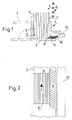
- FIG. 1 shows a device 1 for the production of book blocks formed from adhesive-bound printed sheets, the printed sheets 2 stacked 5 lying one on top of the other along a winding guide wall 3, and on a support element 4 protruding from the lower edge of the guide wall approximately at right angles, which together form the tail unit of a conveyor channel 6 , transported to a book block feeder of a perfect binder in the gathering channel of a collating machine, which cannot be seen, and are thereby moved from a horizontal to a vertical position, the printed sheets 2 with their back fold edges being placed on the supporting element 4 or forming the book block spine to be processed later.
- the support element 4 forms a sliding guide, which could also be designed as a rolling surface or driven with greater effort.
- the chain-dotted lines indicate the horizontal or slightly oblique starting position of the conveyor channel 6 in the area of the collating machine there.
- the twist reaches about 90 ° by the end of the conveyor channel 6.
- a guide rail 7 is assigned to the conveyor channel 6 approximately parallel to the guide wall 3 at an (approximately) parallel distance - which is adjustable.
- the stacks 5 arriving from the collating machine have a mushroom-like cross section due to the back fold edge of the printed sheets 2 on the support element 4. This non-uniform stack cross-sectional shape places special demands on trouble-free operation in the conveying channel 6.
- the friction between the individual printed sheets 2 is higher than between the outer printed sheets 2 and the guide wall 3 or the guide rail 7 of the conveying channel.
- This requirement can be met via the adjusting force of the guide rail 7. be managed; If the contact force is too high, the back fold edges of the printed sheets 2 result in a higher pressure on the guide wall 3 and the guide rail 7, which has, among other things, impaired the processing in the known embodiment.
- This guide rail 7 thus brings about a certain compression in the stack 5 and, as mentioned, can be adjusted according to the height of a stack 5 from printed sheets 2, the guide rail 7 being connected to a stationary frame or the like.
- the adjustability is, for example, telescopic or by means of threaded spindles.
- a parallel rust-like side guide 8 connects to the latter and prevents the free-standing hanging of the stack 5 from tilting to the side in the approximately vertical position.
- This side guide 8 formed from individual bars can be adjusted in connection with the guide rail 7 or independently.
- the slot-like opening 9 which results or is provided with respect to the stack height due to the adjustability of the guide rail 7 between the latter and the support element 4 and which extends over the length of the guide rail 7 is through to shut off a filling element 10 which at least approximately reaches the conveying channel 6 or at least partially projects into the latter and is fed in from the outside in such a way that the printed sheet 2 of a stack 5 sliding along the guide rail 7 does not get into the opening 8 and is jammed there.
- a brush ensures, the bristles 11 of which are placed against the support element 4 or are prestressed against them, in order to create a situation with which the opening 9 in the delivery channel is closed. At the same time, the ends of the bristles 11 bring about a conveyor channel wall which complements the guide rail 7.
- the bristles 11 pass through the opening 9 of the guide rail 7 and partially protrude into the conveying channel 6, then they are pushed according to FIG. 2 by the leading edge of a stack 5 passing through the conveying channel in the conveying direction. This can reduce the scratching effect of the bristle tips on the outermost printed sheet 2; the pretension of the bristles 11 against the support element 4 is retained.
- the bristles 11 of the brush are fastened in a shaft 12 at the end opposite the conveying channel 6. anchored. This shaft 12 can be connected to the guide rail 7 for its adjustability. The pretension of the bristles 11 on the support element 4 can also be adjusted via the shaft 12.
Landscapes
- Feeding Of Articles By Means Other Than Belts Or Rollers (AREA)
- Folding Of Thin Sheet-Like Materials, Special Discharging Devices, And Others (AREA)
- Pile Receivers (AREA)
Abstract
Description
- Die Erfindung betrifft eine Vorrichtung für die Fertigung von aus klebegebundenen Druckbogen gebildeten Buchblöcken, die in Stapeln aufeinandliegend zusammengetragener Druckbogen entlang einer gewundenen Leitwand, von der etwa horizontalen in eine senkrechte Lage versetzt werden, und einen durch ein an der Leitwandunterkante etwa rechtwinklig abstehenden, den Stapel an den Rückenfalzkanten der Druckbogen führenden Abstützelement sowie einem hinsichtlich Stapelhöhe durch eine verstellbare Führungsschiene ausgebildeten Förderkanal passieren.
- Bekanntlich erfolgt das Zusammentragen der verschiedenen Druckbogen zu losen Stapeln in einer Zusammentragmaschine aus mehreren in Reihe stehenden Anlegern. Dabei werden die Druckbogen von den Anlegern mit der den Rücken des herzustellenden Buchblockes bildenden Rückenfalzkante voraus im Sammelkanal der Zusammentragmaschine üblicherweise aufeinanderliegend abgelegt bzw. in der richtigen Reihenfolge zu einem vollständigen, losen Buchblock gesammelt.
- Der Sammelkanal der Zusammentragmaschine nimmt hierzu möglicherweise eine leicht geneigte Flachlage ein.
An den Sammelkanal der Zusammentragmaschine schliesst ein Förderkanal an, dem die gleiche Fördervorrichtung mit Mitnehmern wie dem Sammelkanal zugeordnet und der Gegenstand der vorliegenden Erfindung ist. - Im Förderkanal, auch Überführungskanal genannt, werden die Stapel entlang einer gewundenen Leitwand und einem an der Unterkante dieser abstehenden, den Stapel an den Rückenfalzkanten der Druckbogen führenden Abstützelement von einer etwa horizontalen in eine senkrechte Lage versetzt bzw. aufgestellt.
Gegen das Umkippen des Stapels ist auf der der gewundenen Leitwand gegenüberliegenden Seite des Stapels eine Führungsschiene vorgesehen, die bezüglich Stapelhöhe verstellbar ausgebildet ist. - Durch die Verwindung des Förderkanals, insbesondere des Abstützelementes, lässt sich bei der bekannten Vorrichtung entlang der Führungsschiene durch deren Verstellbarkeit über die gesamte Förderkanallänge ein schlitzähnliches Klaffen zwischen Abstützelement und Führungsschiene nicht vermeiden. Diese Situation kann zu einer Beeinträchtigung des Förderflusses führen, indem beispielsweise die entlang der Führungsschiene gleitenden Druckbogen mit der Rückenfalzkante in diesen schlitzartigen Öffnungen eingeklemmt und zurückgehalten werden, wodurch u. a. der Verarbeitungsprozess unterbrochen wird.
- Durch den auf den Buchblock ausgeübten Zusammhaltdruck, wird dieser Effekt noch begünstigt.
- Das Aufteilen der Führungsschiene in kürzere Abschnitte entlang des Abstützelementes kann das Bilden von keilartig wirkenden Ausnehmungen nicht verhindern.
- Aufgabe der vorliegenden Erfindung ist es somit, eine Vorrichtung der eingangs genannten Art zu schaffen, die die Verstellbarkeit des Abstandes zwischen Leitfläche und Führungsschiene und einen weitgehend störungsfreien Transport der Stapel im Förderkanal gewährleistet.
- Erfindungsgemäss wird diese Aufgabe dadurch gelöst, dass in der zwischen Abstützelement und Führungsschiene vorgesehenen Öffnung ein wenigstens annähernd an bzw. teilweise in den Förderkanal reichendes, an das Abstützelement anlegbares Füllelement angeordnet ist.
Dadurch kann die auf die Druckbogen wirkende Einklemmtendenz an der Führungslängskante zwischen Abstützelement und Führungsschiene weitestgehend behoben werden. - Durch eine seitlich wirkende Vorspannkraft der Borsten kann die Verbindung zwischen Füllelement und Abstützelement optimiert werden.
- Als besonders vorteilhaft erweist sich als Füllelement eine Bürste, mit etwa senkrecht zum Förderkanal die Öffnung wenigstens annähernd durchsetzenden Borsten, wobei die Spitzen der Borsten etwa fluchtend zu der eine Kanalwand bildenden Führungsschiene enden.
Sofern die Borsten in den freien Förderkanal ragen, werden sie durch die vorauslaufende Kante der passierenden Druckbogenstapel in eine nach der Förderrichtung abweichende Schräglage versetzt und lösen einen günstigen Gegendruck auf die gesammelten Druckbogen aus. - Eine Bürste erweist sich als Füllelement besonders günstig, wenn die Borsten in der Öffnung gegen das Abstützelement anliegend beaufschlagbar sind, sodass die Bildung einer Klemmstelle verhindert wird.
- Um die Lage und/oder den Anpressdruck der Borsten an dem Abstützelement ändern zu können, ist der die Borsten der Bürste einenends aufnehmende Schaft verstellbar ausgebildet.
- Nachsthend ist die erfindungsgemässe Vorrichtung anhand eines in einer Zeichnung dargestellten Ausführungsbeispiels näher erläutert. Es veranschaulichen:
- Fig. 1
- einen Querschnitt durch den Förderkanal der erfindungsgemässen Vorrichtung und
- Fig. 2
- einen Längsschnitt durch den Förderkanal gemäss der Linie II - II in Fig. 1.
- Fig. 1 zeigt eine Vorrichtung 1 für die Fertigung von aus klebegebundenen Druckbogen gebildeten Buchblöcken, die in Stapeln 5 aufeinanderliegend zusammengetragener Druckbogen 2 entlang einer gewundenen Leitwand 3, und auf einem von der Leitwandunterkante etwa rechtwinklig abstehenden Abstützelement 4, die zusammen Leitwerk eines Förderkanals 6 bilden, im Sammelkanal einer nicht ersichtlichen Zusammentragmaschine zu einem Buchblockanleger eines Klebebinders transportiert und dabei von einer horizontalen in eine senkrechte Lage versetzt werden, wobei die Druckbogen 2 mit ihren Rückenfalzkanten auf dem Abstützelement 4 abgestellt sind bzw. den später zu bearbeitenden Buchblockrücken bilden. Das Abstützelement 4 bildet eine Gleitführung, die mit grösserem Aufwand auch als Rollfläche oder angetrieben ausgebildet sein könnte. Die strickpunktierten Linien deuten auf die horizontale oder leicht schräge Ausgangslage des Förderkanals 6 im Bereich der Zusammentragmaschine hin. Die Verwindung erreicht bis zum Ende des Förderkanals 6 etwa 90°.
Im Anschluss an die Zusammentragmaschine ist dem Förderkanal 6 etwa parallel zu der Leitwand 3 eine Führungsschiene 7 in einem (etwa) parallelen Abstand - der verstellbar ausgebildet ist - zugeordnet. Die von der Zusammentragmaschine ankommenden Stapel 5 weisen aufgrund der Rückenfalzkante der Druckbogen 2 am Abstützelement 4 einen pilzartig erweiterten Querschnitt auf. Diese ungleichmässige Stapelquerschnittsform stellt besondere Anforderungen an einen störungsfreien Betrieb im Förderkanal 6. Die Reibung zwischen den einzelnen Druckbogen 2 ist höher als zwischen den äusseren Druckbogen 2 und der Leitwand 3 bzw. der Führungsschiene 7 des Förderkanals. Diese Forderung kann über die Anstellkraft der Führungsschiene 7 erfüllt resp. geregelt werden; ist die Anstellkraft zu hoch, dann entsteht durch die Rückenfalzkanten der Druckbogen 2 ein höherer Druck an der Leitwand 3 und der Führungsschiene 7, der u.a. bei der bekannten Ausführungsform zur Beeinträchtigung der Verarbeitung geführt hat. Diese Führungsschiene 7 bewirkt also eine gewisse Verdichtung in dem Stapel 5 und kann, wie erwähnt, entsprechend der Höhe eines Stapels 5 aus Druckbogen 2 verstellt werden, wobei die Führungsschiene 7 mit einem ortsfesten Gestell oder dgl. verbunden ist. Die Verstellbarkeit erfolgt beispielsweise teleskopartig oder durch Gewindespindeln. Als Ergänzung der Führungsschiene 7 schliesst eine parallel verlaufende rostartige Seitenführung 8 an letztere an und verhindert, dass der freistehende Aushang des Stapels 5 in der etwa senkrechten Lage nicht zur Seite kippt. Diese aus einzelnen Stäben gebildete Seitenführung 8 kann in Verbindung mit der Führungsschiene 7 oder unabhängig verstellt werden. Die hinsichtlich Stapelhöhe durch die Verstellbarkeit der Führungsschiene 7 zwischen letzterer und dem Abstützelement 4 sich ergebende bzw. vorgesehene schlitzartige Öffnung 9, die sich über die Länge der Führungsschiene 7 erstreckt, ist durch ein wenigstens annähernd an den Förderkanal 6 reichendes oder in letzteren wenigstens teilweise hineinragenden, von aussen zugeführtes Füllelement 10 so abzusperren, dass der an der Führungsschiene 7 entlanggleitende Druckbogen 2 eines Stapels 5 nicht in die Öffnung 8 gelangt und dort verklemmt wird. Dagegen sorgt beispielsweise eine Bürste, deren Borsten 11 an das Abstützelement 4 angelegt oder dagegen vorgespannt ist, um mit diesem eine die Öffnung 9 im Förderkanal absperrende Situation zu schaffen. Gleichzeitig bewirken die Borsten 11 mit ihren Enden eine die Führungsschiene 7 ergänzende Förderkanalwand. - Durchsetzen die Borsten 11 die Öffnung 9 der Führungsschiene 7 und ragen sie teilweise in den Förderkanal 6, dann werden sie gemäss Fig. 2 durch die vorauslaufende Kante eines den Förderkanal passierenden Stapels 5 in Förderrichtung abgedrängt. Dadurch kann die Kratzwirkung der Borstenspitzen auf den äussersten Druckbogen 2 gemindert werden; die Vorspannung der Borsten 11 gegen das Abstützelement 4 bleibt erhalten.
Die Borsten 11 der Bürste sind an dem dem Förderkanal 6 gegenüberliegenden Ende in einem Schaft 12 befestigt resp. verankert. Dieser Schaft 12 kann zu seiner Verstellbarkeit mit der Führungsschiene 7 verbunden sein. Über den Schaft 12 lässt sich auch die Vorspannung der Borsten 11 an dem Abstützelement 4 verstellen.
Claims (5)
- Vorrichtung für die Fertigung von aus klebegebundenen Druckbogen gebildeten Buchblöcken, die in Stapeln aufeinanderliegend zusammengetragener Druckbogen entlang einer gewundenen Leitwand, von der etwa horizontalen in eine senkrechte Lage versetzt werden, und einen durch ein an der Leitwandunterkante etwa rechtwinklig abstehenden, den Stapel an den Rückenfalzkanten der Druckbogen führenden Abstützelement sowie einem hinsichtlich Stapelhöhe durch eine verstellbare Führungsschiene ausgebildeten Förderkanal passieren, dadurch gekennzeichnet, dass in der zwischen Abstützelement (4) und Führungsschiene (7) vorgesehenen Öffnung (9) ein wenigstens annähernd an bzw. teilweise in den Förderkanal (6) reichendes, an das Abstützelement (4) anlegbares Füllelement (10) angeordnet ist.
- Vorrichtung nach Anspruch 1, dadurch gekennzeichnet, dass das Füllelement (10) gegen das Abstützelement (4) vorgespannt angeordnet ist.
- Vorrichtung nach Anspruch 1 oder 2, dadurch gekennzeichnet, dass das Füllelement (10) als Bürste mit etwa senkrecht zum Förderkanal (6) die Öffnung (9) wenigstens annähern durchsetzenden Borsten (11) ausgebildet ist.
- Vorrichtung nach Anspruch 3, dadurch gekennzeichnet, dass die Borsten (11) der Bürste in der Öffnung (9) gegen das Abstützelement (4) beaufschlagt sind.
- Vorrichtung nach Anspruch 4, dadurch gekennzeichnet, dass die Borsten (11) einseitig in einem verstellbaren Schaft (12) der Bürste befestigt sind.
Applications Claiming Priority (3)
| Application Number | Priority Date | Filing Date | Title |
|---|---|---|---|
| CH2893/93 | 1993-09-24 | ||
| CH289393 | 1993-09-24 | ||
| CH893/93 | 1993-09-24 |
Publications (2)
| Publication Number | Publication Date |
|---|---|
| EP0645261A1 true EP0645261A1 (de) | 1995-03-29 |
| EP0645261B1 EP0645261B1 (de) | 1997-03-26 |
Family
ID=4243970
Family Applications (1)
| Application Number | Title | Priority Date | Filing Date |
|---|---|---|---|
| EP94810526A Expired - Lifetime EP0645261B1 (de) | 1993-09-24 | 1994-09-13 | Vorrichtung für die Fertigung von aus klebegebundenen Druckbogen gebildeten Buchblöcken |
Country Status (4)
| Country | Link |
|---|---|
| US (1) | US5499897A (de) |
| EP (1) | EP0645261B1 (de) |
| JP (1) | JPH07172664A (de) |
| DE (1) | DE59402213D1 (de) |
Cited By (2)
| Publication number | Priority date | Publication date | Assignee | Title |
|---|---|---|---|---|
| CN104553440A (zh) * | 2013-10-17 | 2015-04-29 | 曼罗兰网络系统有限责任公司 | 用于形成书芯的装置 |
| EP3216619A1 (de) * | 2016-03-07 | 2017-09-13 | Müller Martini Holding AG | Vorrichtung und verfahren zum transport von buchblocks |
Citations (2)
| Publication number | Priority date | Publication date | Assignee | Title |
|---|---|---|---|---|
| CH408857A (de) * | 1964-02-21 | 1966-03-15 | Leipziger Buchbindereimaschine | Winkelförderbahn für papierverarbeitende Maschinen |
| CH516408A (de) * | 1970-11-04 | 1971-12-15 | Martini Buchbindermaschf | Querstapelauslage |
Family Cites Families (3)
| Publication number | Priority date | Publication date | Assignee | Title |
|---|---|---|---|---|
| US5232324A (en) * | 1991-10-07 | 1993-08-03 | Quad/Tech, Inc. | Apparatus and method for applying covers to signatures |
| JP3046976B2 (ja) * | 1992-05-27 | 2000-05-29 | ホリゾン・インターナショナル株式会社 | 製本機用排出装置 |
| DE4236033A1 (de) * | 1992-10-24 | 1994-06-01 | Kolbus Gmbh & Co Kg | Umschlaganlegevorrichtung für eine Buchbindemaschine |
-
1994
- 1994-09-06 US US08/301,173 patent/US5499897A/en not_active Expired - Fee Related
- 1994-09-13 EP EP94810526A patent/EP0645261B1/de not_active Expired - Lifetime
- 1994-09-13 DE DE59402213T patent/DE59402213D1/de not_active Expired - Fee Related
- 1994-09-16 JP JP6221842A patent/JPH07172664A/ja not_active Withdrawn
Patent Citations (2)
| Publication number | Priority date | Publication date | Assignee | Title |
|---|---|---|---|---|
| CH408857A (de) * | 1964-02-21 | 1966-03-15 | Leipziger Buchbindereimaschine | Winkelförderbahn für papierverarbeitende Maschinen |
| CH516408A (de) * | 1970-11-04 | 1971-12-15 | Martini Buchbindermaschf | Querstapelauslage |
Cited By (2)
| Publication number | Priority date | Publication date | Assignee | Title |
|---|---|---|---|---|
| CN104553440A (zh) * | 2013-10-17 | 2015-04-29 | 曼罗兰网络系统有限责任公司 | 用于形成书芯的装置 |
| EP3216619A1 (de) * | 2016-03-07 | 2017-09-13 | Müller Martini Holding AG | Vorrichtung und verfahren zum transport von buchblocks |
Also Published As
| Publication number | Publication date |
|---|---|
| US5499897A (en) | 1996-03-19 |
| DE59402213D1 (de) | 1997-04-30 |
| EP0645261B1 (de) | 1997-03-26 |
| JPH07172664A (ja) | 1995-07-11 |
Similar Documents
| Publication | Publication Date | Title |
|---|---|---|
| EP0675005B1 (de) | Einrichtung zum Klebebinden von Druckereiprodukten | |
| EP2258559B1 (de) | Buchfertigungsstrasse zur Herstellung von aus einer Buchdecke und einem in diese eingehängten Buchblock gebildeten Büchern. | |
| EP0623542A1 (de) | Einrichtung zur Bildung eines sich senkrecht zu den stehend aneinandergereihten Druckbogen erstreckenden Stapels | |
| CH651525A5 (de) | Vorrichtung zum buendeln von papierblaettern, z.b. papiergeld. | |
| EP1645434A1 (de) | Einrichtung zur taktweisen Verarbeitung von aus wenigstens einem Druckbogen gebildeten Buchblocks | |
| DE3143762A1 (de) | "papierfoerdervorrichtung fuer eine rotationsdruckpresse" | |
| EP0712736B1 (de) | Verfahren zur Herstellung von klebegebundenen Büchern, Broschuren oder dgl. Produkten | |
| DE2335358C3 (de) | Automatische Maschine zum Transport und Aufnähen der Signaturen in Büchern | |
| DE3244422A1 (de) | Schneidevorrichtung fuer bogen sowie hefte mit mindestens einem rotierenden schneidmesser und einer foerdervorrichtung | |
| EP2050701A1 (de) | Einrichtung zum Sammeln von Druckbogen | |
| EP1886833A1 (de) | Verfahren und Vorrichtung zur Herstellung eines aus mehreren Druckprodukten gebildeten klebegebundenen Druckerzeugnisses | |
| EP0645261B1 (de) | Vorrichtung für die Fertigung von aus klebegebundenen Druckbogen gebildeten Buchblöcken | |
| EP0732222B1 (de) | Verfahren und Vorrichtung für das Anbringen eines Umschlages am Rücken eines aus gebundenen Druckbogen gebildeten Buchblockes | |
| EP0194461A2 (de) | Ausfuhreinrichtung für Klebebindemaschinen | |
| EP0659586A1 (de) | Verfahren zur Beschickung von zu Druckprodukten gesammelten, mehrblättrigen Druckbogen mit Beilagen | |
| EP0831045B1 (de) | Verfahren und Vorrichtung zum Öffnen von flexiblen, flächigen Erzeugnissen | |
| DE10135659A1 (de) | Fördereinrichtung zur Förderung von Gegenständen, insbesondere von Druckprodukten | |
| DE1561141A1 (de) | Vorrichtung zum OEffnen eines mehrblaettrigen Papiererzeugnisses an einer durch Reibungsminderung vorbestimmten Stelle und zum Einfuehren einer Beilage in das geoeffnete Erzeugnis | |
| EP0387726B1 (de) | Vorrichtung zur Uebernahme, Speicherung und Abgabe von Falzprodukten | |
| DE2109468C2 (de) | Faltmaschine zum Umlegen der Laschen von Faltschachteln | |
| EP2030801B1 (de) | Verfahren zur Herstellung von aus zusammengetragenen Druckbogen gebildeten klebegebundenen Buchblocks und entsprechende Vorrichtung | |
| EP1886832A1 (de) | Verfahren und Vorrichtung zur Herstellung eines aus mehreren Druckprodukten gebildeten klebegebundenen Druckerzeugnisses | |
| EP1418146B1 (de) | Vorrichtung zum Sammeln und Bearbeiten von gefalteten Druckprodukten | |
| EP0818325B1 (de) | Vorrichtung zum Anlegen von Vorsätzen an Buchblocks | |
| EP1050499A1 (de) | Vorrichtung zum Zuführen von flächigen Gegenständen zu einer Verarbeitungseinrichtung |
Legal Events
| Date | Code | Title | Description |
|---|---|---|---|
| PUAI | Public reference made under article 153(3) epc to a published international application that has entered the european phase |
Free format text: ORIGINAL CODE: 0009012 |
|
| AK | Designated contracting states |
Kind code of ref document: A1 Designated state(s): CH DE FR GB IT LI |
|
| 17P | Request for examination filed |
Effective date: 19950710 |
|
| GRAG | Despatch of communication of intention to grant |
Free format text: ORIGINAL CODE: EPIDOS AGRA |
|
| 17Q | First examination report despatched |
Effective date: 19960702 |
|
| GRAH | Despatch of communication of intention to grant a patent |
Free format text: ORIGINAL CODE: EPIDOS IGRA |
|
| GRAH | Despatch of communication of intention to grant a patent |
Free format text: ORIGINAL CODE: EPIDOS IGRA |
|
| GRAA | (expected) grant |
Free format text: ORIGINAL CODE: 0009210 |
|
| AK | Designated contracting states |
Kind code of ref document: B1 Designated state(s): CH DE FR GB IT LI |
|
| REG | Reference to a national code |
Ref country code: CH Ref legal event code: EP |
|
| REF | Corresponds to: |
Ref document number: 59402213 Country of ref document: DE Date of ref document: 19970430 |
|
| GBT | Gb: translation of ep patent filed (gb section 77(6)(a)/1977) |
Effective date: 19970627 |
|
| ET | Fr: translation filed | ||
| PGFP | Annual fee paid to national office [announced via postgrant information from national office to epo] |
Ref country code: FR Payment date: 19970731 Year of fee payment: 4 |
|
| PGFP | Annual fee paid to national office [announced via postgrant information from national office to epo] |
Ref country code: DE Payment date: 19970910 Year of fee payment: 4 |
|
| PGFP | Annual fee paid to national office [announced via postgrant information from national office to epo] |
Ref country code: CH Payment date: 19971222 Year of fee payment: 4 |
|
| PLBE | No opposition filed within time limit |
Free format text: ORIGINAL CODE: 0009261 |
|
| STAA | Information on the status of an ep patent application or granted ep patent |
Free format text: STATUS: NO OPPOSITION FILED WITHIN TIME LIMIT |
|
| 26N | No opposition filed | ||
| PG25 | Lapsed in a contracting state [announced via postgrant information from national office to epo] |
Ref country code: GB Free format text: LAPSE BECAUSE OF NON-PAYMENT OF DUE FEES Effective date: 19980913 |
|
| PG25 | Lapsed in a contracting state [announced via postgrant information from national office to epo] |
Ref country code: LI Free format text: LAPSE BECAUSE OF NON-PAYMENT OF DUE FEES Effective date: 19980930 Ref country code: CH Free format text: LAPSE BECAUSE OF NON-PAYMENT OF DUE FEES Effective date: 19980930 |
|
| GBPC | Gb: european patent ceased through non-payment of renewal fee |
Effective date: 19980913 |
|
| REG | Reference to a national code |
Ref country code: CH Ref legal event code: PL |
|
| PG25 | Lapsed in a contracting state [announced via postgrant information from national office to epo] |
Ref country code: FR Free format text: LAPSE BECAUSE OF NON-PAYMENT OF DUE FEES Effective date: 19990531 |
|
| REG | Reference to a national code |
Ref country code: FR Ref legal event code: ST |
|
| PG25 | Lapsed in a contracting state [announced via postgrant information from national office to epo] |
Ref country code: IT Free format text: LAPSE BECAUSE OF NON-PAYMENT OF DUE FEES;WARNING: LAPSES OF ITALIAN PATENTS WITH EFFECTIVE DATE BEFORE 2007 MAY HAVE OCCURRED AT ANY TIME BEFORE 2007. THE CORRECT EFFECTIVE DATE MAY BE DIFFERENT FROM THE ONE RECORDED. Effective date: 20050913 |