EP0645293A1 - Wagon à marchandises pour former un train de wagons ferroviaires pour transport rail-route - Google Patents
Wagon à marchandises pour former un train de wagons ferroviaires pour transport rail-route Download PDFInfo
- Publication number
- EP0645293A1 EP0645293A1 EP94112243A EP94112243A EP0645293A1 EP 0645293 A1 EP0645293 A1 EP 0645293A1 EP 94112243 A EP94112243 A EP 94112243A EP 94112243 A EP94112243 A EP 94112243A EP 0645293 A1 EP0645293 A1 EP 0645293A1
- Authority
- EP
- European Patent Office
- Prior art keywords
- loading platform
- freight
- centering
- guide
- freight car
- Prior art date
- Legal status (The legal status is an assumption and is not a legal conclusion. Google has not performed a legal analysis and makes no representation as to the accuracy of the status listed.)
- Granted
Links
Images



Classifications
-
- B—PERFORMING OPERATIONS; TRANSPORTING
- B61—RAILWAYS
- B61D—BODY DETAILS OR KINDS OF RAILWAY VEHICLES
- B61D3/00—Wagons or vans
- B61D3/04—Wagons or vans with movable floors, e.g. rotatable or floors which can be raised or lowered
-
- B—PERFORMING OPERATIONS; TRANSPORTING
- B60—VEHICLES IN GENERAL
- B60P—VEHICLES ADAPTED FOR LOAD TRANSPORTATION OR TO TRANSPORT, TO CARRY, OR TO COMPRISE SPECIAL LOADS OR OBJECTS
- B60P1/00—Vehicles predominantly for transporting loads and modified to facilitate loading, consolidating the load, or unloading
- B60P1/64—Vehicles predominantly for transporting loads and modified to facilitate loading, consolidating the load, or unloading the load supporting or containing element being readily removable
- B60P1/6409—Vehicles predominantly for transporting loads and modified to facilitate loading, consolidating the load, or unloading the load supporting or containing element being readily removable details, accessories, auxiliary devices
-
- B—PERFORMING OPERATIONS; TRANSPORTING
- B61—RAILWAYS
- B61D—BODY DETAILS OR KINDS OF RAILWAY VEHICLES
- B61D3/00—Wagons or vans
- B61D3/16—Wagons or vans adapted for carrying special loads
- B61D3/20—Wagons or vans adapted for carrying special loads for forwarding containers
Definitions
- the invention is based on a freight wagon according to the preamble of claim 1, as is known for example from CH-PS 666 452. Similar freight cars are also shown in AT-PS 335 507 or DE 40 20 387 A1.
- air suspension bellows are supported on the wagon chassis symmetrically to the longitudinal center axis to form on-board lifting means, the upper end of which, which is to be taken over or removed, has interchangeable superstructures for reasons of mechanical stabilization of the air bellows via a rocker arm articulated on the wagon chassis .
- the swap bodies set up on integrated stilts in the track area must be positioned very precisely in relation to the tracks in the transverse direction and with regard to the parallel alignment, so that they can then be taken over by index pins on the loading platforms of the freight wagons.
- locking bars which can be moved outwards are provided along both longitudinal sides of the loading platform of the freight wagon; These can be placed on the inside of the stilts of a swap body, which hangs laterally from the loading platform, to secure the position during rail transport.
- the interchangeable bodies can be aligned relative to the loading platform of the freight car with the locking bars that can be moved laterally under high force; a very precise setup of the swap bodies before the goods wagons are taken with regard to their lateral position and parallel alignment to the tracks is therefore not necessary.
- the freight wagon known from CH-PS 666 452 has a frame-shaped wagon chassis which carries indexing and locking means on its upper side, which interact directly with the indexing and locking means attached to the body.
- the swap bodies to be parked on the truck side above the train track are positioned with a certain degree of accuracy with regard to transverse position and parallelism with the help of two light barriers, which are aligned parallel to the tracks and which determine the transverse tolerance of the swap bodies, with a desired position to be observed when parking the swap body Position in relation to the longitudinal direction is defined by a floor marking.
- the freight wagon has onboard front and rear lifting devices formed by air bellows, the top of which is transverse to the wagon chassis and the two together and as a whole in the longitudinal direction relative to the wagon chassis by means of a hand crank and Screw drive are displaceable.
- the two lifting devices are provided with cylindrical centering disks which are rotatably mounted about a centrally arranged vertical axis. Their dimensions correspond to the functionally identical centering discs on the trucks and they work together with a flat, rectangular centering tunnel that runs through the center of the underside of the swap bodies.
- the freight wagon In order for the freight wagon to take over the swap body parked with relatively coarse positional tolerances to the tracks, it must first be centered by the on-board lifting means to the wagon chassis with much smaller tolerances.
- the centering disks are raised to the height of the centering tunnel in the freight wagons that are brought into readiness in the longitudinal direction in front of or behind the swap body, and the goods wagon is inserted under the swap body, the ones that move transversely on the top Lifting means are automatically centered relative to the swap body due to the interaction of the centering discs and the centering tunnel.
- the freight wagon In the longitudinal direction, the freight wagon must be brought to a standstill with a certain positional tolerance in relation to the swap body.
- the stilts By further lifting the on-board lifting equipment including the swap body, the stilts can be relieved and these can be retracted and stowed. Simultaneously with this lifting, the inclined edges and deflection rollers integrated in the air suspension bellows center and align the transversely movable lifting means and the swap body they support to the car chassis. Before the interchangeable body is lowered into the chassis-side indexing and locking means, the interchangeable body and the lifting means carrying it must be aligned together in the longitudinal direction of the car chassis, for which purpose the manually driven screw drive is provided. After an appropriate longitudinal alignment, the interchangeable body can be lowered and locked into the chassis-side indexing and locking means.
- the object of the invention is to improve the generic freight wagons in such a way that swap bodies of different heights can be taken over efficiently with a small footprint and in the train set.
- the swap bodies made available for takeover can not only be lined up at a very close distance, i.e. with very little space requirement, but also the swap bodies provided can be rationally moved from one to the other Train association coupled freight cars are taken over. After taking over the swap bodies and aligning the loading platform to them on the one hand when the wagon is at a standstill and the automatic alignment of the loading platform to the wagon chassis on the other hand by lowering the loading platform, practically all possible limits can be reached within certain limits imposed by construction practice Storage heights of the swap bodies are allowed for the takeover process, so that the system is quite flexible in so far.
- Swap bodies 6 are provided for combined long-distance freight transport by rail and road, which are already being used in large numbers today in purely road-bound freight transport on trucks.
- the inventive design of freight wagons 1 is intended to enable these swap bodies to also be transferred to suitable freight wagons.
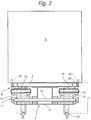
- the freight wagons 1 provided for this purpose have a loading platform 3 without a tailgate, which serve to accommodate such swap bodies.
- the swap bodies 6 are placed symmetrically on the platform 25 on four integrated stilts 4 at truck level.
- the floor must be level in the track area, ie the rails must be sunk into the floor in such a way that the rail heads lie flush with the driving surface.
- floor markings 7 are recorded, on which the stilts 4 of the swap bodies must come to rest so that the swap bodies are in relation to the tracks with accuracy that is suitable for a takeover.
- the floor markings are formed by a rectangle within which the stilts must stand; the floor-marked rectangle represents, as it were, the tolerance range for the installation of the swap bodies when the truck is set down.
- the clearance profile of the empty freight wagons 1 is lower in height and width over its entire length than the clearance profile below the swap bodies parked above the tracks 25.
- on-board lifting devices equipped with air suspension bellows 5 are provided, with which a swap body can be raised and lowered by at least about 40 cm in order to be able to take over swap bodies with a clear installation height of 1320 mm. Due to horizontal mobility in the longitudinal and transverse directions in the lifting means, the interchangeable structure which they accommodate can be aligned in the raised state with respect to the longitudinal central axis and the transverse axis of the freight wagon 1 for indexing accuracy.
- the loading platform 3 is designed as a separate part relative to the wagon chassis, which is movable relative to it and which by means of the on-board lifting means by the amounts mentioned can be raised and lowered.
- the on-board lifting means which will be discussed in greater detail below, are connected to the loading platform 3 in a horizontally movable manner in three degrees of freedom of movement on their upper side via a horizontal floating guide 8.
- the floating guide is designed in such a way that a displacement of the loading platform in the longitudinal and transverse directions in each case by a displacement dimension corresponding to the installation tolerance of the swap bodies over the tracks 25 and a pivoting of the loading platform about a vertical axis within the scope of the displacement dimension in any combination of the three mentioned Enables movements is.
- the opening of the centering funnel 9 is greater than the displacement dimension of the loading platform 3 with respect to the lifting means or within the floating guide 8.
- the tip of the centering pin 10 When the loading platform is in the raised state, the tip of the centering pin 10 is located axially in the region of the largest clear diameter of the associated centering funnel 9, whereas in the lowered state Condition of the loading platform, the tip comes to lie axially beyond the smallest clear diameter.
- the floating guide 8 attached to the lifting devices on the upper side is kinematically and positionally matched by means of two hinged on the right and left of the carriage chassis
- Parallelogram guides 11 which are rigidly connected to one another by means of a connecting shaft 12. This ensures that all four corners of the in principle rectangular floating guide mechanically always have the same height in all stroke positions, even under very different loads.
- the rockers 13 of the parallelogram guide are articulated on the underside of the carriage chassis 2 to the connecting shaft 12 already mentioned; on the upper side they are articulated on the floating guide 8 or the guide plate 18.
- the rockers 13 must have a certain minimum width.
- the carriage chassis is formed by a tubular central carrier 14 running along the longitudinal center line of the freight carriage over its length, which in the illustrated embodiment is rectangular in cross section, although with different Profile height, trained is.
- the central support 14 In the area of the bogies 24, the central support 14 is flatter, whereas it has a greater overall height in the central area, which is more subject to bending in the vertical direction.
- cross members 16 are attached to the central support 14 and serve to support the guide plate 18 including the interchangeable structure 6 in the transport position.
- the brackets 15 are not attached directly to the central support 14, but are part of the lower lifting frame, which is in turn adjustable at its two ends on cross members which are attached to the central support, but this is not shown in the drawing.
- the brackets 15 have different functions: on the one hand, they should transfer the lifting forces into the wagon through the front brackets for the bellows 5, on the other hand, together with the rear support brackets, they should prevent vibrations of the rockers 13 while driving.
- At the end of each cross member 17 are attached to the central support 14 for holding the clutch buffer 23.
- the two parallelogram guides are articulated on both sides of the central support 14.
- the air bellows 5 of the lifting means already mentioned several times are supported on the underside on the already mentioned brackets 15;
- the air bellows 5 engage on the upper side on the underside of the rockers 13 of the parallelogram guide 8.
- Such a stroke ratio is necessary so that the required lifting height can also be applied for the highest swap bodies 6 by the lifting means in a small installation space.
- swap bodies with different installation heights are used.
- the guide plate 18 is provided with a plurality of circumferences for the loading platform 3 in order to prevent the floating loading platform from tipping over from the guide plate, but this is not shown in the drawing.
- the lifting means mentioned several times are in the illustrated embodiment by the parallelogram 11 with the wings 13 and the air bellows 5 engaging on the underside of the rockers.
- the floating guide of the loading platform which has also already been mentioned several times, is formed on the one hand by a guide plate 18 held on the right and left on the parallelogram guides and on the other hand by a corresponding support plate 19 on the underside of the loading platform 3. So that the loading platform 3 can be moved horizontally as smoothly as possible by the floating guide 8, the guide plates 18 carry a plurality of evenly distributed roller balls 20 on the top side, which project slightly above the guide plates and which in turn are each mounted so that they can move easily and in a sealed manner in a bearing housing 21.
- the support plates 19 attached to the underside of the loading platform are formed by flat, hardened, welded steel plates.
- the guide and support plates 18 and 19 are limited to the right and left side strips, the guide plates 18 only having to have a number of rolling balls 20; the width of the support plates 19 must correspond to the previously mentioned displacement dimension or the installation tolerance of the swap bodies.
- the loading platform 3 is provided with first indexing and locking means 22 for mutually locking the loading platform 3 with the swap body to be accommodated, these locking means also preventing the swap body from being lifted or tilted relative to the loading platform to back up.
- first indexing and locking means interact with body-side indexing and locking means, which are also used for indexing and locking the swap bodies on the truck.
- further means are provided on the loading platform 3 and on the carriage chassis 2 for mutually transport-safe locking of the loading platform on the carriage chassis, also against lifting and tipping of the loading platform.
- the two horizontally spaced pairs of centering elements - centering pin 10 and centering funnel 9 - are arranged off-center in the area of the two transverse ends of the loading platform so that they are diagonally opposite one another across the center of the platform .
- their distance base and thus the centering accuracy are increased compared to another arrangement with a smaller horizontal distance between the two pairs of centering elements.
- two loading platforms 3 are arranged one behind the other on the car body 2 of the freight car, which can be lifted and lowered by means of separate lifting means and by means of separate swimming guides are horizontally displaceable.
- the two swap bodies to be accommodated on a freight wagon can be aligned and centered for themselves.
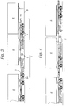
- the freight train must also come to a standstill in a defined longitudinal position in relation to the floor markings so that the lined swap bodies can all be taken over. It is important here that the length tolerances between the individual freight cars must not exceed a certain level. If necessary, precautions must be taken that make the train set so rigid, at least for the time the freight wagons are loaded, that the tolerances mentioned can be adhered to.
- the state of the longitudinal positioning of the freight train under the lined swap bodies 6 is illustrated in FIG. 4.
- the individual loading platforms in the partially raised state but unloaded are aligned manually and with a view to the swap bodies and - after lifting the platform - the platform-side first indexing means 22 are threaded into the corresponding counter-indexing means on the swap bodies and locked.
- the horizontal movement of the loading platform in the floating guide can be carried out with little force that can be applied manually.
- the swap bodies can be lifted off the floor, so that the stilts 4 can be released from the floor and retracted and stowed away in the usual manner on the swap bodies. 5, however, the raised state is still shown with hanging stilts 4.
- swap and destination-specific traffic of the swap bodies from a certain starting station to a certain destination station is provided.
- the swap bodies can be transferred to the lorries that transport the swap bodies in the area to their respective destination in the opposite direction.
- the process of this envelope is simpler and less complex, since the containers cannot be positioned precisely.
- the swap bodies are parked in a row on a section of track that can be driven on by road vehicles, and are gradually picked up by truck from freight forwarders based there.
- FIGS. 9 and 10 Another possibility of centering the loading platform under load will be discussed in connection with FIGS. 9 and 10.
- means are provided for power-assisted centering of the loading platform 3, which is almost completely lowered but is still movable on the floating guide 8.
- pressure webs 26 are arranged on the loading platform in the corner region of the loading platform and extend parallel to the outer sides thereof.
- pressure rollers 27 On the carriage chassis 2 cooperating with the pressure bars pressure rollers 27 are arranged with a vertical axis of rotation, each of which is horizontally displaceable by an amount corresponding at least to the installation tolerance of the swap bodies 6.
- two pressure rollers are assigned to each corner, which are mounted at the ends of a three-armed pivot lever 31, which in turn is pivotably mounted on a pivot bearing 32 assigned to the carriage chassis.
- the piston rod 30 of an actuating piston 28 that can be acted upon by fluid engages in an articulated manner.
- a return spring 29 arranged in the cylinder returns the piston, and with it the pivoting lever, after venting the working space with atmospheric pressure to the basic position shown in FIG. 9, in which the pressure rollers are retracted.
- the pivot levers By pressurizing the pistons 28 via the fluid line 39, the pivot levers are pivoted by approximately 90 ° into the centering position shown in FIG. 10, the associated pressure rollers passing into the centering outer position.
- the arm lengths of the arms of the pivot lever which are provided with pressure rollers, are dimensioned in connection with the position of the chassis-fixed pivot bearings 32 in such a way that, on the one hand, the above-mentioned displacement stroke of the pressure rollers in the longitudinal or transverse direction results and, on the other hand, the exact centering position the loading position 3 determining end position is mechanically defined.
- the loading platform which is under load but still movably resting on the floating guide, is horizontally displaced and possibly pivoted over the pressure webs such that the longitudinal axis 36 associated with the loading platform, its transverse axis 37 and its Center 38 lie in the same position as the longitudinal axis 33 to be assigned to the car chassis, the corresponding transverse axis 34 or the associated center 35.
- the last-mentioned option is based, among other things, on the fact that the handling technology according to the invention does not use the center tunnel for the swap bodies according to DIN EN 284, but that swap bodies which are flat or of any design can be adopted without difficulty.
- the first indexing and locking means of the loading platforms 3 must match the corresponding counter-indexing and locking means of the swap bodies; at least appropriate indexing means must be provided or convertible on the platform side.
Landscapes
- Engineering & Computer Science (AREA)
- Transportation (AREA)
- Mechanical Engineering (AREA)
- Loading Or Unloading Of Vehicles (AREA)
- Sawing (AREA)
- Vehicle Body Suspensions (AREA)
Applications Claiming Priority (2)
| Application Number | Priority Date | Filing Date | Title |
|---|---|---|---|
| DE4332266 | 1993-09-23 | ||
| DE19934332266 DE4332266C2 (de) | 1993-09-23 | 1993-09-23 | Güterwagen zur Bildung eines schienengebundenen Güterzuges für den kombinierten Güterverkehr Schiene/Straße |
Publications (2)
| Publication Number | Publication Date |
|---|---|
| EP0645293A1 true EP0645293A1 (fr) | 1995-03-29 |
| EP0645293B1 EP0645293B1 (fr) | 1997-05-28 |
Family
ID=6498341
Family Applications (1)
| Application Number | Title | Priority Date | Filing Date |
|---|---|---|---|
| EP19940112243 Expired - Lifetime EP0645293B1 (fr) | 1993-09-23 | 1994-08-05 | Wagon à marchandises pour former un train de wagons ferroviaires pour transport rail-route |
Country Status (4)
| Country | Link |
|---|---|
| EP (1) | EP0645293B1 (fr) |
| CZ (1) | CZ284212B6 (fr) |
| DE (1) | DE4332266C2 (fr) |
| ES (1) | ES2103095T3 (fr) |
Cited By (10)
| Publication number | Priority date | Publication date | Assignee | Title |
|---|---|---|---|---|
| FR2747351A1 (fr) * | 1996-04-10 | 1997-10-17 | Plouznikoff Paul | Dispositif rendant amovibles par elevation tout types de carrosseries solidaires de leurs porteurs |
| EP0795451A3 (fr) * | 1996-03-11 | 1998-05-06 | Max Aicher GmbH Entsorgungstechnik | Dispositif de levage pour un plateau de base posé horizontalement |
| US6530580B1 (en) | 1999-05-12 | 2003-03-11 | John Edward Simpson | Suspension assembly related application |
| WO2003020564A1 (fr) * | 2001-09-05 | 2003-03-13 | Rail-Road Nonstop Logistics Ab | Wagon de marchandises pour transport de conteneurs sur rails |
| WO2003020565A1 (fr) * | 2001-09-05 | 2003-03-13 | Rail-Road Nonstop Logistics Ab | Procede et systeme au niveau d'une zone de rechargement |
| WO2003020566A1 (fr) * | 2001-09-05 | 2003-03-13 | Rail-Road Nonstop Logistics Ab | Dispositif de levage a cable conçu pour un wagon de marchandises sur rails |
| EP2634062A1 (fr) * | 2012-02-29 | 2013-09-04 | Peter Wanek-Pusset | Wagon porte-container 80 pieds |
| CN106184242A (zh) * | 2016-07-27 | 2016-12-07 | 中车石家庄车辆有限公司 | 轨道平板车 |
| EP3423713A4 (fr) * | 2016-02-29 | 2019-11-20 | Advanced Rail Energy Storage, LLC | Système de stockage d'énergie electrique à entraînement par câble de ligne de crête |
| CN111439280A (zh) * | 2020-03-16 | 2020-07-24 | 中铁上海工程局集团有限公司 | 一种新型地铁正线轨道通用施工运输车及其使用方法 |
Families Citing this family (2)
| Publication number | Priority date | Publication date | Assignee | Title |
|---|---|---|---|---|
| DE10153876A1 (de) * | 2001-11-02 | 2003-05-22 | Knorr Bremse Systeme | Eisenbahnwaggon |
| DE102012105636A1 (de) | 2012-06-27 | 2014-04-17 | Rte Technologie Gmbh | Hubvorrichtung für Wechselaufbauten |
Citations (5)
| Publication number | Priority date | Publication date | Assignee | Title |
|---|---|---|---|---|
| US2959303A (en) * | 1959-07-09 | 1960-11-08 | Harry A Wheltle | Lading transfer system |
| FR1293688A (fr) * | 1960-04-22 | 1962-05-18 | Procédé et installation pour accélérer le transport de containers par le rail etla route | |
| AT335507B (de) * | 1974-10-07 | 1977-03-10 | Kaessbohrer Fahrzeug Karl | Eisenbahnwaggon fur den transport von mit ausstellbaren bodenstutzen versehenen wechselaufbauten, containern od.dgl. |
| CH666452A5 (en) * | 1983-11-17 | 1988-07-29 | Gutzwiller & Partner | Superstructure transloading mechanism for rail truck - which has rotary centring cylindrical plates, coacting with hoist, coacting with fine centring mechanism |
| DE4020387A1 (de) * | 1990-06-27 | 1991-08-08 | Daimler Benz Ag | Gueterwagen zur bildung eines schienengebundenen gueterzuges fuer den kombinierten gueterverkehr schiene/strasse |
Family Cites Families (1)
| Publication number | Priority date | Publication date | Assignee | Title |
|---|---|---|---|---|
| US3161150A (en) * | 1960-12-06 | 1964-12-15 | Donald E Sable | Load receiving, supporting and cushioning apparatus |
-
1993
- 1993-09-23 DE DE19934332266 patent/DE4332266C2/de not_active Expired - Lifetime
-
1994
- 1994-08-05 ES ES94112243T patent/ES2103095T3/es not_active Expired - Lifetime
- 1994-08-05 EP EP19940112243 patent/EP0645293B1/fr not_active Expired - Lifetime
- 1994-09-15 CZ CZ942256A patent/CZ284212B6/cs not_active IP Right Cessation
Patent Citations (5)
| Publication number | Priority date | Publication date | Assignee | Title |
|---|---|---|---|---|
| US2959303A (en) * | 1959-07-09 | 1960-11-08 | Harry A Wheltle | Lading transfer system |
| FR1293688A (fr) * | 1960-04-22 | 1962-05-18 | Procédé et installation pour accélérer le transport de containers par le rail etla route | |
| AT335507B (de) * | 1974-10-07 | 1977-03-10 | Kaessbohrer Fahrzeug Karl | Eisenbahnwaggon fur den transport von mit ausstellbaren bodenstutzen versehenen wechselaufbauten, containern od.dgl. |
| CH666452A5 (en) * | 1983-11-17 | 1988-07-29 | Gutzwiller & Partner | Superstructure transloading mechanism for rail truck - which has rotary centring cylindrical plates, coacting with hoist, coacting with fine centring mechanism |
| DE4020387A1 (de) * | 1990-06-27 | 1991-08-08 | Daimler Benz Ag | Gueterwagen zur bildung eines schienengebundenen gueterzuges fuer den kombinierten gueterverkehr schiene/strasse |
Cited By (11)
| Publication number | Priority date | Publication date | Assignee | Title |
|---|---|---|---|---|
| EP0795451A3 (fr) * | 1996-03-11 | 1998-05-06 | Max Aicher GmbH Entsorgungstechnik | Dispositif de levage pour un plateau de base posé horizontalement |
| FR2747351A1 (fr) * | 1996-04-10 | 1997-10-17 | Plouznikoff Paul | Dispositif rendant amovibles par elevation tout types de carrosseries solidaires de leurs porteurs |
| US6530580B1 (en) | 1999-05-12 | 2003-03-11 | John Edward Simpson | Suspension assembly related application |
| WO2003020564A1 (fr) * | 2001-09-05 | 2003-03-13 | Rail-Road Nonstop Logistics Ab | Wagon de marchandises pour transport de conteneurs sur rails |
| WO2003020565A1 (fr) * | 2001-09-05 | 2003-03-13 | Rail-Road Nonstop Logistics Ab | Procede et systeme au niveau d'une zone de rechargement |
| WO2003020566A1 (fr) * | 2001-09-05 | 2003-03-13 | Rail-Road Nonstop Logistics Ab | Dispositif de levage a cable conçu pour un wagon de marchandises sur rails |
| EP2634062A1 (fr) * | 2012-02-29 | 2013-09-04 | Peter Wanek-Pusset | Wagon porte-container 80 pieds |
| EP3423713A4 (fr) * | 2016-02-29 | 2019-11-20 | Advanced Rail Energy Storage, LLC | Système de stockage d'énergie electrique à entraînement par câble de ligne de crête |
| AU2017225864B2 (en) * | 2016-02-29 | 2022-02-17 | Advanced Rail Energy Storage, L.L.C. | Ridgeline cable drive electric energy storage system |
| CN106184242A (zh) * | 2016-07-27 | 2016-12-07 | 中车石家庄车辆有限公司 | 轨道平板车 |
| CN111439280A (zh) * | 2020-03-16 | 2020-07-24 | 中铁上海工程局集团有限公司 | 一种新型地铁正线轨道通用施工运输车及其使用方法 |
Also Published As
| Publication number | Publication date |
|---|---|
| DE4332266C2 (de) | 1995-07-13 |
| CZ225694A3 (en) | 1995-06-14 |
| CZ284212B6 (cs) | 1998-09-16 |
| EP0645293B1 (fr) | 1997-05-28 |
| ES2103095T3 (es) | 1997-08-16 |
| DE4332266A1 (de) | 1995-03-30 |
Similar Documents
| Publication | Publication Date | Title |
|---|---|---|
| EP1993894B1 (fr) | Système de transbordement de marchandises et wagon ferroviaire conçu à cet effet | |
| DE102009012159B4 (de) | Güterumschlageinrichtung für den kombinierten Güterverkehr | |
| DE69330237T2 (de) | Kupplungseinheit zwischen zwei aufeinander folgenden Waggons und einem gemeinsamen Drehgestell | |
| DE69803556T2 (de) | Eisenbahn- umschlageinrichtung für container und eisenbahnwagen | |
| DE102004040245A1 (de) | Güterumschlagverfahren und Transportsystem | |
| EP1519868B1 (fr) | Procede de chargement et de dechargement de wagons de chemin de fer et dispositif, chassis de wagon et superstructure de wagon pour mettre ledit procede en oeuvre | |
| WO1998058828A1 (fr) | Systeme de transbordement | |
| EP2384947A1 (fr) | Procédé et dispositif de chargement du transport de marchandises sur le rail | |
| EP0645293B1 (fr) | Wagon à marchandises pour former un train de wagons ferroviaires pour transport rail-route | |
| EP2792515B1 (fr) | Système de véhicule destiné à transporter des marchandises sur rails et sur routes, kit de rééquipement de wagon d'un système de véhicule destiné à transporter des marchandises sur rails et sur routes et procédé de rééquipement | |
| EP0019098B1 (fr) | Wagon couvert | |
| DE69020545T2 (de) | Schienentransportwagen für Nutzfahrzeuge. | |
| DE4304635A1 (de) | Eisenbahn-Niederflurwagen einer Sonderbauart | |
| DE102016224869B4 (de) | Transportvorrichtung | |
| EP0623498A1 (fr) | Dispositif de chargement pour porte-charges | |
| CH624361A5 (en) | Device for loading and unloading a road-bound or rail-bound vehicle | |
| DE10258405A1 (de) | Transportvorrichtung | |
| DE9105882U1 (de) | Güterwaggon der Eisenbahn | |
| EP3296175B1 (fr) | Procede de transport de semi-remorque | |
| DE3502226A1 (de) | Schienengebundenes transportfahrzeug, insbesondere zum transport von personenkraftwagen | |
| EP0005517B1 (fr) | Support avec verrouillage pour le transport des semi-remorques par chemin de fer | |
| CH693334A5 (de) | Umsetzvorrichtung fürLasteinheiten. | |
| DE4128008A1 (de) | Wechselsystem fuer abnehmbare aufbauten von lastkraftwagen | |
| DE202016008550U1 (de) | Eisenbahnwagon mit einem auf ihm abgesetzten Sattelauflieger | |
| EP0362187A1 (fr) | Système de transport par chemin de fer |
Legal Events
| Date | Code | Title | Description |
|---|---|---|---|
| PUAI | Public reference made under article 153(3) epc to a published international application that has entered the european phase |
Free format text: ORIGINAL CODE: 0009012 |
|
| AK | Designated contracting states |
Kind code of ref document: A1 Designated state(s): CH ES FR GB IT LI SE |
|
| 17P | Request for examination filed |
Effective date: 19950204 |
|
| 17Q | First examination report despatched |
Effective date: 19960116 |
|
| GRAG | Despatch of communication of intention to grant |
Free format text: ORIGINAL CODE: EPIDOS AGRA |
|
| GRAH | Despatch of communication of intention to grant a patent |
Free format text: ORIGINAL CODE: EPIDOS IGRA |
|
| GRAH | Despatch of communication of intention to grant a patent |
Free format text: ORIGINAL CODE: EPIDOS IGRA |
|
| GRAA | (expected) grant |
Free format text: ORIGINAL CODE: 0009210 |
|
| AK | Designated contracting states |
Kind code of ref document: B1 Designated state(s): CH ES FR GB IT LI SE |
|
| REG | Reference to a national code |
Ref country code: CH Ref legal event code: NV Representative=s name: ISLER & PEDRAZZINI AG Ref country code: CH Ref legal event code: EP |
|
| GBT | Gb: translation of ep patent filed (gb section 77(6)(a)/1977) |
Effective date: 19970624 |
|
| ET | Fr: translation filed | ||
| REG | Reference to a national code |
Ref country code: ES Ref legal event code: FG2A Ref document number: 2103095 Country of ref document: ES Kind code of ref document: T3 |
|
| RAP2 | Party data changed (patent owner data changed or rights of a patent transferred) |
Owner name: DAIMLER-BENZ AKTIENGESELLSCHAFT |
|
| REG | Reference to a national code |
Ref country code: GB Ref legal event code: 732E |
|
| REG | Reference to a national code |
Ref country code: FR Ref legal event code: TP |
|
| PLBE | No opposition filed within time limit |
Free format text: ORIGINAL CODE: 0009261 |
|
| STAA | Information on the status of an ep patent application or granted ep patent |
Free format text: STATUS: NO OPPOSITION FILED WITHIN TIME LIMIT |
|
| RAP2 | Party data changed (patent owner data changed or rights of a patent transferred) |
Owner name: LOHR INDUSTRIE |
|
| 26N | No opposition filed | ||
| REG | Reference to a national code |
Ref country code: CH Ref legal event code: PUE Owner name: DAIMLER-BENZ AKTIENGESELLSCHAFT TRANSFER- LOHR IND Ref country code: CH Ref legal event code: NV Representative=s name: CABINET ROLAND NITHARDT CONSEILS EN PROPRIETE INDU |
|
| REG | Reference to a national code |
Ref country code: GB Ref legal event code: 732E |
|
| REG | Reference to a national code |
Ref country code: FR Ref legal event code: TP Ref country code: FR Ref legal event code: CD |
|
| REG | Reference to a national code |
Ref country code: GB Ref legal event code: IF02 |
|
| PGFP | Annual fee paid to national office [announced via postgrant information from national office to epo] |
Ref country code: GB Payment date: 20020723 Year of fee payment: 9 |
|
| PGFP | Annual fee paid to national office [announced via postgrant information from national office to epo] |
Ref country code: SE Payment date: 20020822 Year of fee payment: 9 |
|
| PGFP | Annual fee paid to national office [announced via postgrant information from national office to epo] |
Ref country code: ES Payment date: 20020930 Year of fee payment: 9 |
|
| PG25 | Lapsed in a contracting state [announced via postgrant information from national office to epo] |
Ref country code: GB Free format text: LAPSE BECAUSE OF NON-PAYMENT OF DUE FEES Effective date: 20030805 |
|
| PG25 | Lapsed in a contracting state [announced via postgrant information from national office to epo] |
Ref country code: SE Free format text: LAPSE BECAUSE OF NON-PAYMENT OF DUE FEES Effective date: 20030806 Ref country code: ES Free format text: LAPSE BECAUSE OF NON-PAYMENT OF DUE FEES Effective date: 20030806 |
|
| GBPC | Gb: european patent ceased through non-payment of renewal fee |
Effective date: 20030805 |
|
| EUG | Se: european patent has lapsed | ||
| REG | Reference to a national code |
Ref country code: ES Ref legal event code: FD2A Effective date: 20030806 |
|
| PG25 | Lapsed in a contracting state [announced via postgrant information from national office to epo] |
Ref country code: IT Free format text: LAPSE BECAUSE OF NON-PAYMENT OF DUE FEES Effective date: 20050805 |
|
| PGFP | Annual fee paid to national office [announced via postgrant information from national office to epo] |
Ref country code: CH Payment date: 20060724 Year of fee payment: 13 |
|
| REG | Reference to a national code |
Ref country code: CH Ref legal event code: PL |
|
| PG25 | Lapsed in a contracting state [announced via postgrant information from national office to epo] |
Ref country code: LI Free format text: LAPSE BECAUSE OF NON-PAYMENT OF DUE FEES Effective date: 20070831 Ref country code: CH Free format text: LAPSE BECAUSE OF NON-PAYMENT OF DUE FEES Effective date: 20070831 |
|
| REG | Reference to a national code |
Ref country code: FR Ref legal event code: GC Effective date: 20120924 |
|
| REG | Reference to a national code |
Ref country code: FR Ref legal event code: RG Effective date: 20121122 |
|
| PGFP | Annual fee paid to national office [announced via postgrant information from national office to epo] |
Ref country code: FR Payment date: 20130829 Year of fee payment: 20 |