EP0645302A1 - Méthode et dispositif pour un conversion plus effectif de l'énergie propulsive d'un bateau, en vitesse - Google Patents
Méthode et dispositif pour un conversion plus effectif de l'énergie propulsive d'un bateau, en vitesse Download PDFInfo
- Publication number
- EP0645302A1 EP0645302A1 EP94114601A EP94114601A EP0645302A1 EP 0645302 A1 EP0645302 A1 EP 0645302A1 EP 94114601 A EP94114601 A EP 94114601A EP 94114601 A EP94114601 A EP 94114601A EP 0645302 A1 EP0645302 A1 EP 0645302A1
- Authority
- EP
- European Patent Office
- Prior art keywords
- water
- air
- nozzle
- jet
- watercraft
- Prior art date
- Legal status (The legal status is an assumption and is not a legal conclusion. Google has not performed a legal analysis and makes no representation as to the accuracy of the status listed.)
- Withdrawn
Links
- 238000000034 method Methods 0.000 title claims abstract description 17
- 230000001141 propulsive effect Effects 0.000 title abstract 2
- 238000006243 chemical reaction Methods 0.000 title description 2
- XLYOFNOQVPJJNP-UHFFFAOYSA-N water Substances O XLYOFNOQVPJJNP-UHFFFAOYSA-N 0.000 claims abstract description 82
- 239000000203 mixture Substances 0.000 claims abstract description 11
- 230000033001 locomotion Effects 0.000 claims description 9
- 239000012791 sliding layer Substances 0.000 claims description 3
- 238000002347 injection Methods 0.000 abstract description 4
- 239000007924 injection Substances 0.000 abstract description 4
- 241000238634 Libellulidae Species 0.000 abstract 1
- 238000010276 construction Methods 0.000 abstract 1
- 230000009172 bursting Effects 0.000 description 2
- 238000009412 basement excavation Methods 0.000 description 1
- 230000015572 biosynthetic process Effects 0.000 description 1
- 230000000694 effects Effects 0.000 description 1
- 239000010410 layer Substances 0.000 description 1
- 239000000243 solution Substances 0.000 description 1
- 238000009827 uniform distribution Methods 0.000 description 1
Images

Classifications
-
- B—PERFORMING OPERATIONS; TRANSPORTING
- B63—SHIPS OR OTHER WATERBORNE VESSELS; RELATED EQUIPMENT
- B63H—MARINE PROPULSION OR STEERING
- B63H11/00—Marine propulsion by water jets
- B63H11/02—Marine propulsion by water jets the propulsive medium being ambient water
-
- B—PERFORMING OPERATIONS; TRANSPORTING
- B63—SHIPS OR OTHER WATERBORNE VESSELS; RELATED EQUIPMENT
- B63B—SHIPS OR OTHER WATERBORNE VESSELS; EQUIPMENT FOR SHIPPING
- B63B1/00—Hydrodynamic or hydrostatic features of hulls or of hydrofoils
- B63B1/32—Other means for varying the inherent hydrodynamic characteristics of hulls
- B63B1/34—Other means for varying the inherent hydrodynamic characteristics of hulls by reducing surface friction
- B63B1/38—Other means for varying the inherent hydrodynamic characteristics of hulls by reducing surface friction using air bubbles or air layers gas filled volumes
-
- B—PERFORMING OPERATIONS; TRANSPORTING
- B63—SHIPS OR OTHER WATERBORNE VESSELS; RELATED EQUIPMENT
- B63B—SHIPS OR OTHER WATERBORNE VESSELS; EQUIPMENT FOR SHIPPING
- B63B1/00—Hydrodynamic or hydrostatic features of hulls or of hydrofoils
- B63B1/32—Other means for varying the inherent hydrodynamic characteristics of hulls
- B63B1/34—Other means for varying the inherent hydrodynamic characteristics of hulls by reducing surface friction
- B63B1/38—Other means for varying the inherent hydrodynamic characteristics of hulls by reducing surface friction using air bubbles or air layers gas filled volumes
- B63B2001/387—Other means for varying the inherent hydrodynamic characteristics of hulls by reducing surface friction using air bubbles or air layers gas filled volumes using means for producing a film of air or air bubbles over at least a significant portion of the hull surface
-
- Y—GENERAL TAGGING OF NEW TECHNOLOGICAL DEVELOPMENTS; GENERAL TAGGING OF CROSS-SECTIONAL TECHNOLOGIES SPANNING OVER SEVERAL SECTIONS OF THE IPC; TECHNICAL SUBJECTS COVERED BY FORMER USPC CROSS-REFERENCE ART COLLECTIONS [XRACs] AND DIGESTS
- Y02—TECHNOLOGIES OR APPLICATIONS FOR MITIGATION OR ADAPTATION AGAINST CLIMATE CHANGE
- Y02T—CLIMATE CHANGE MITIGATION TECHNOLOGIES RELATED TO TRANSPORTATION
- Y02T70/00—Maritime or waterways transport
- Y02T70/10—Measures concerning design or construction of watercraft hulls
Definitions
- the invention relates to a method and a device for its implementation for more effective conversion of the drive energies of fast-moving watercraft into speed, preferably while maintaining the hull shape typical of gliders.
- the invention has for its object to develop a method and an apparatus which avoid these disadvantages.
- the method according to the invention is based on the fact that the kinetic energy contained in the outgoing thrust jet is not uselessly dissipated behind the watercraft in the form of water eddies, waves and noise, but is used to substantially reduce the frictional forces occurring in the air between the hull and the incoming water is injected between a sliding floor of the watercraft and part of the inflowing water, so that a sliding layer of an air-water mixture forms between them.
- the thrust nozzle of a water jet drive known per se is preferably moved from the rear area according to the invention into the injection devices installed on or in the sliding floor.
- the number and arrangement of these devices is chosen so that a uniform distribution of the air-water mixture over the sliding floor is achieved.
- the air injection takes place according to the Venturi principle, as is also used in the water jet pump, the design for the method according to the invention preferably being modified.
- the water supply to the pump or turbine producing pressurized water is expediently carried out there by guide strips which protrude from the sliding surface into the incoming water and have openings at the bottom. These guide strips can simultaneously serve to limit the lateral sliding surface and take over the function of a keel or sword.
- the advantage of using the method according to the invention is that no additional energy has to be used to reduce the sliding friction.
- the drive power contained in the outgoing thrust jet in the form of kinetic energy is thus converted into speed more effectively than known drives, without the hull shape customary for gliders having to be changed significantly.
- the high-energy jet water is obtained indirectly by utilizing the sliding speed of the watercraft and the resultant dynamic pressure of the incoming water.
- the device according to the invention is provided with a water inlet, at the end of which there is the nozzle which effects the air injection already described. For this procedure it is irrelevant whether the thrust of the watercraft is generated with sail or with motor power.
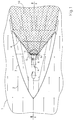
- the device 3 has a wedge-like, streamlined shape, not unlike a lying V, which rises from the tip to the legs and ends with a likewise V-shaped tear-off edge 4.
- 5 shows the arrangement of the devices 3, below the sliding floor 1, as a wedge-like, streamlined elevation on the sliding floor 1, with the tip pointing in the direction of travel. If the speed now increases, the inflowing water 2 is lifted off the sliding base 1 due to the wedge shape. 3, an almost water-free space 7 is formed. The boundary of the water-free space 7 occurs, on the one hand, through the sliding floor 1, in the direction of travel through the tear-off edge 4 of the device 3, and through that Water flowing over the tear-off edge 4.
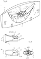
- the nozzle 9 shown in FIG. 9 is located in a cavity 5. which sets the pressure water 14 flowing through in a helical rotational movement. This additional rotational movement of the pressurized water 14 has the result that the jet water 15 emerging from the nozzle 9 is divided into many high-energy individual jets or water drops. Air is sucked into the resulting gaps and passes through air duct openings 6 in the sliding floor 1 into the mouth region of the nozzle 9. Appropriate design of the device 3 and the air supply in the mouth region of the nozzle 9 with the cavity 5, as can be seen in FIG.
- the special elliptical shape of the nozzle mouth 11 results in a fan-shaped jet pattern which is adapted to the profile of the tear-off edge 4.
- the kinetic energy of the jet water 15 drives the air-water mixture 16 formed in the mixing space 17 into the collecting space 22 behind the device 3 and thereby prevents the inflowing water 2 from contacting the sliding floor again.
- the air-water mixture 16 is applied to the entire sliding floor 1 or a large part thereof by a corresponding number and arrangement of the device 3, which brings about a substantial reduction in water friction.
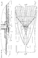
- FIGS. 7 and 8 show a modified device according to FIGS. 1 to 3.
- the high-energy jet water 15 required for the generation of the air-water mixture 16 is obtained indirectly, by utilizing the speed of the watercraft and the resulting dyn. Pressure of the incoming water 2, generated.
- a part of the incoming water 2 is detected according to its cross section and fed to the nozzle 9.
- the propulsion of the watercraft can be done by means of a conventional ship propulsion, but also by using wind power, e.g. by means of sail.
- the nozzle 9 shows the nozzle 9 in three views.
- the nozzle inlet is equipped with a swirl blading 12, which generates a radial movement in addition to the axial movement of the inflowing water 2.
- the shape of the blade is designed in such a way that the lowest possible resistances and losses occur.
- Four guide vanes 12 are preferably provided, a smaller or larger number also being possible.
- the guide vanes 12 are attached to the nozzle jacket 10, and the blade depth is smaller than the radius of the nozzle 9, so that a center jet remains unaffected.
- the leading edge 13 of the blades is sharpened.
- this cutting edge is beveled in the longitudinal direction, so that inflowing foreign bodies are guided from the periphery to the center.
- the surfaces of the guide vanes 12 and the nozzle 9 are provided with very little roughness, so that a very good nozzle efficiency is achieved.
- a more or less strong bursting of the jet water 15 emerging from the nozzle 9 into many individual jets or water drops is caused. In that way air is sucked.
- the nozzle mouth 11 essentially has the shape of a flat ellipse, as a result of which the emerging and bursting jet water 15 receives a likewise flat, fan-shaped widening profile which is adapted to the profile of the tear-off edge 4 of the device 3.
- a further advantageous embodiment of the device according to FIG. 8 is that a drive propeller is provided to generate the jet water 15 provided with a swirl in the water inlet 8 to the nozzle 9, the propeller being able to simultaneously provide the thrust for the locomotion of the watercraft.
- the swirl of the jet water 15 is caused by the rotation of the propeller
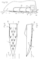
- FIG. 10 shows a guide bar 18 which is attached below the sliding floor 1 and projects into the inflowing water 2 and is provided with inlet openings 21 for the water supply of the jet drive 19.
- Pipelines 20 first supply the water to the pump / turbine 19 and then to the nozzle 9.
- the guide bar 18 can simultaneously take over the function of a keel or sword.
Landscapes
- Chemical & Material Sciences (AREA)
- Engineering & Computer Science (AREA)
- Combustion & Propulsion (AREA)
- Mechanical Engineering (AREA)
- Ocean & Marine Engineering (AREA)
- Physics & Mathematics (AREA)
- Fluid Mechanics (AREA)
- Cleaning Or Clearing Of The Surface Of Open Water (AREA)
- Wind Motors (AREA)
- Nozzles (AREA)
Applications Claiming Priority (2)
| Application Number | Priority Date | Filing Date | Title |
|---|---|---|---|
| DE4332358A DE4332358C2 (de) | 1993-09-23 | 1993-09-23 | Verfahren und Vorrichtung zur wirkungsvolleren Umsetzung der Antriebsenergien von Wasserfahrzeugen in Geschwindigkeit |
| DE4332358 | 1993-09-23 |
Publications (1)
| Publication Number | Publication Date |
|---|---|
| EP0645302A1 true EP0645302A1 (fr) | 1995-03-29 |
Family
ID=6498404
Family Applications (1)
| Application Number | Title | Priority Date | Filing Date |
|---|---|---|---|
| EP94114601A Withdrawn EP0645302A1 (fr) | 1993-09-23 | 1994-09-16 | Méthode et dispositif pour un conversion plus effectif de l'énergie propulsive d'un bateau, en vitesse |
Country Status (2)
| Country | Link |
|---|---|
| EP (1) | EP0645302A1 (fr) |
| DE (1) | DE4332358C2 (fr) |
Cited By (7)
| Publication number | Priority date | Publication date | Assignee | Title |
|---|---|---|---|---|
| EP1074748A1 (fr) * | 1999-08-03 | 2001-02-07 | Maytronics Ltd. | Tube de sortie pour hélice rotative |
| US7997221B2 (en) * | 2009-03-23 | 2011-08-16 | Dan Nicolaus Costas | Apparatus for reducing drag on a nautical vessel |
| US8327784B2 (en) | 2009-03-23 | 2012-12-11 | Dan Nicolaus Costas | Apparatus for generating and distributing compressed air for reducing drag |
| US8763547B2 (en) | 2012-07-25 | 2014-07-01 | Dan Nicolaus Costas | Apparatus for lowering drag on a moving nautical vessel |
| KR101980738B1 (ko) * | 2019-04-05 | 2019-05-22 | 조윤규 | 선박의 마찰저항 감소를 위한 워터제트식 공기윤활장치 |
| WO2022071813A1 (fr) * | 2020-09-30 | 2022-04-07 | Venairjet Systems Limited | Appareil et système d'introduction d'air sous une coque de bateau |
| CN115848556A (zh) * | 2023-01-06 | 2023-03-28 | 江南造船(集团)有限责任公司 | 一种凸出船底的气层减阻装置及其安装方法、船舶 |
Families Citing this family (6)
| Publication number | Priority date | Publication date | Assignee | Title |
|---|---|---|---|---|
| DE19739445A1 (de) * | 1997-09-02 | 1999-03-11 | Juergen Dr Ing Heinig | Anordnung zur Erzeugung eines Schiffsvortriebs |
| DE102007053645A1 (de) * | 2007-11-08 | 2009-05-14 | Häußer, Achim | Luftblasenrumpf |
| DE102017007809A1 (de) * | 2017-08-17 | 2019-02-21 | Broder Joachim Merkel | System zur Veränderung der Eigenwelle eines Bootes |
| RU204438U1 (ru) * | 2020-12-11 | 2021-05-25 | Юрий Александрович Белецкий | Водометный турбодвигатель на энергии воздуха высокого давления с использованием микродисперсной воздушно-водяной смеси |
| RU2764312C1 (ru) * | 2021-09-15 | 2022-01-17 | Юрий Александрович Белецкий | Способ перемещения водного транспортного средства |
| CN115180061B (zh) * | 2022-06-24 | 2023-05-16 | 哈尔滨工程大学 | 一种高温空化器、包含高温空化器的超空泡航行体及方法 |
Citations (6)
| Publication number | Priority date | Publication date | Assignee | Title |
|---|---|---|---|---|
| US2764954A (en) * | 1953-04-13 | 1956-10-02 | Oeltgen Bernhard | Propulsion apparatus for water vessels |
| US3342032A (en) * | 1966-06-29 | 1967-09-19 | Clifford B Cox | Jet propulsion means for a boat |
| GB1460947A (en) * | 1974-04-29 | 1977-01-06 | Czerniak M K E | Displacement ducted craft |
| DE3422406A1 (de) * | 1984-06-14 | 1985-12-19 | Studio Böer, 2000 Hamburg | Surfbrett |
| DE8611196U1 (de) * | 1986-04-23 | 1986-09-11 | Reichel, Dieter, 92369 Sengenthal | Vorrichtung zur Verminderung der Reibung bei Wasserfahrzeugen |
| US4979917A (en) * | 1986-10-31 | 1990-12-25 | Haynes Hendrick W | Marine propulsion device with gaseous boundry layer for a thrust jet flow stream exhibiting stealth and ice lubrication properties |
Family Cites Families (16)
| Publication number | Priority date | Publication date | Assignee | Title |
|---|---|---|---|---|
| US2005473A (en) * | 1933-03-13 | 1935-06-18 | Arthur G Sanden | Air-jet propelled conveyance |
| DE886420C (de) * | 1938-01-25 | 1953-08-13 | Charles Sartori | Schnellboot, insbesondere Gleitboot, mit Strahlantrieb |
| US2488183A (en) * | 1944-08-22 | 1949-11-15 | Harry H Garmont | Hull construction |
| DE1198145B (de) * | 1958-08-01 | 1965-08-05 | Firth Cleveland Ltd | Stroemungskoerper, insbesondere Quertriebsflaeche, mit durch Ausblasen von Stroemungsmittelstrahlen beeinflussbarer Zirkulation |
| DE1757603B1 (de) * | 1968-05-24 | 1971-07-08 | Bremshey & Co | Laengenverkuerzbarer Flachschirm |
| GB1323872A (en) * | 1969-10-23 | 1973-07-18 | Defence Secretary For State Fo | Marine propulsion system |
| DE1960204A1 (de) * | 1969-12-01 | 1971-06-09 | Steinroetter Heinz Dipl Ing | Bootskoerper mit mehreren Abreisskanten |
| US3702598A (en) * | 1971-06-07 | 1972-11-14 | Jack J Szptyman | Watercraft |
| BE789208A (fr) * | 1971-09-22 | 1973-01-15 | Hull Francis R | Systeme de propulsion par jet pour navires |
| FR2203353A5 (fr) * | 1972-09-12 | 1974-05-10 | France Etat | |
| US4004542A (en) * | 1973-03-16 | 1977-01-25 | Holmes William H | Waterjet propelled planing hull |
| DE3234954A1 (de) * | 1982-09-21 | 1984-05-10 | Erich Dr. 3400 Göttingen Baum | Vorrichtung zum antrieb eines wasserfahrzeuges |
| DE3320331A1 (de) * | 1983-06-04 | 1984-12-13 | Horst 4800 Bielefeld Duschek | Hochgeschwindigkeitssegelbrett |
| EP0293538A1 (fr) * | 1987-06-04 | 1988-12-07 | Charles Guibernao | Dispositif de réduction du frottement d'une côque de bateau |
| DE3912910A1 (de) * | 1989-04-20 | 1990-10-25 | Gabriel Reinhard | Strahlantrieb fuer wasser- und luftfahrzeuge sowie umwaelzpumpen |
| US5205765A (en) * | 1990-11-27 | 1993-04-27 | The Pinnacle Corporation | Boat hull and propulsion system or the like |
-
1993
- 1993-09-23 DE DE4332358A patent/DE4332358C2/de not_active Expired - Fee Related
-
1994
- 1994-09-16 EP EP94114601A patent/EP0645302A1/fr not_active Withdrawn
Patent Citations (6)
| Publication number | Priority date | Publication date | Assignee | Title |
|---|---|---|---|---|
| US2764954A (en) * | 1953-04-13 | 1956-10-02 | Oeltgen Bernhard | Propulsion apparatus for water vessels |
| US3342032A (en) * | 1966-06-29 | 1967-09-19 | Clifford B Cox | Jet propulsion means for a boat |
| GB1460947A (en) * | 1974-04-29 | 1977-01-06 | Czerniak M K E | Displacement ducted craft |
| DE3422406A1 (de) * | 1984-06-14 | 1985-12-19 | Studio Böer, 2000 Hamburg | Surfbrett |
| DE8611196U1 (de) * | 1986-04-23 | 1986-09-11 | Reichel, Dieter, 92369 Sengenthal | Vorrichtung zur Verminderung der Reibung bei Wasserfahrzeugen |
| US4979917A (en) * | 1986-10-31 | 1990-12-25 | Haynes Hendrick W | Marine propulsion device with gaseous boundry layer for a thrust jet flow stream exhibiting stealth and ice lubrication properties |
Cited By (8)
| Publication number | Priority date | Publication date | Assignee | Title |
|---|---|---|---|---|
| EP1074748A1 (fr) * | 1999-08-03 | 2001-02-07 | Maytronics Ltd. | Tube de sortie pour hélice rotative |
| US7997221B2 (en) * | 2009-03-23 | 2011-08-16 | Dan Nicolaus Costas | Apparatus for reducing drag on a nautical vessel |
| US8327784B2 (en) | 2009-03-23 | 2012-12-11 | Dan Nicolaus Costas | Apparatus for generating and distributing compressed air for reducing drag |
| US8763547B2 (en) | 2012-07-25 | 2014-07-01 | Dan Nicolaus Costas | Apparatus for lowering drag on a moving nautical vessel |
| KR101980738B1 (ko) * | 2019-04-05 | 2019-05-22 | 조윤규 | 선박의 마찰저항 감소를 위한 워터제트식 공기윤활장치 |
| WO2020204606A1 (fr) * | 2019-04-05 | 2020-10-08 | 조윤규 | Dispositif de lubrification à air de type jet d'eau pour réduire la résistance au frottement d'un navire |
| WO2022071813A1 (fr) * | 2020-09-30 | 2022-04-07 | Venairjet Systems Limited | Appareil et système d'introduction d'air sous une coque de bateau |
| CN115848556A (zh) * | 2023-01-06 | 2023-03-28 | 江南造船(集团)有限责任公司 | 一种凸出船底的气层减阻装置及其安装方法、船舶 |
Also Published As
| Publication number | Publication date |
|---|---|
| DE4332358C2 (de) | 1997-03-06 |
| DE4332358A1 (de) | 1995-03-30 |
Similar Documents
| Publication | Publication Date | Title |
|---|---|---|
| DE3876297T2 (de) | Aero-/hydrodynamische tragflaeche. | |
| DE69020357T2 (de) | Schnelles einrumpfboot mit hydrodynamischem auftrieb oder einrumpfhalbgleitboot. | |
| EP0645302A1 (fr) | Méthode et dispositif pour un conversion plus effectif de l'énergie propulsive d'un bateau, en vitesse | |
| WO2003101820A1 (fr) | Systeme d'entrainement pour vaisseau marin rapide, notamment pour navire de guerre | |
| DE2438147C2 (de) | Antriebseinrichtung für Schiffe | |
| DE1506810B2 (de) | Vorrichtung zur steuerung und oder stabilisierung eines luft oder wasserfahrzeugs | |
| CH651794A5 (de) | Wasserstrahl-antriebsvorrichtung zum antrieb von wasserfahrzeugen. | |
| EP1718524A1 (fr) | Systeme d'entrainement auxiliaire par deviation du courant de fluide | |
| DD241056A1 (de) | Vorrichtung zur erhoehung des wirkungsgrades von schiffspropellern | |
| DE2416562A1 (de) | Vorrichtung zur verringerung von geschwindigkeitsdifferenzen in einer den scheibenbereich eines schiffspropellers durchsetzenden stroemung | |
| DE3338132A1 (de) | Stroemungsmaschine, insbesondere fuer geringe stroemungsgeschwindigkeiten | |
| EP1663769A1 (fr) | Bateau | |
| DE3642914A1 (de) | Wasserfahrzeug | |
| DE3320331A1 (de) | Hochgeschwindigkeitssegelbrett | |
| DE3129232A1 (de) | "propeller" | |
| WO2018069044A1 (fr) | Dispositif permettant de réduire au minimum la résistance au frottement de véhicules marins à corps déplaceurs | |
| DE1049712B (fr) | ||
| DE102017101055A1 (de) | Motorbetriebenes wasserfahrzeug und verfahren zur reduktion der reibung an schiffsrümpfen | |
| DE102008016147A1 (de) | Verfahren und Einrichtung zur Verbesserung der Hydrodynamik bei Schiffen mit Bug | |
| DE29908430U1 (de) | Schnelles seegehendes Schiff | |
| DE1266163B (de) | Catamaranfahrzeug | |
| DE2644844B1 (de) | Verfahren und einrichtung zum einfuehren von gas und wasser in den propellerbereich eines strahlruders | |
| DE2828787C2 (de) | Manövriertriebwerk für Wasserfahrzeuge | |
| DE683298C (de) | Schiffskoerper mit Auftriebsflaechen | |
| DE613208C (de) | Hinterschiffsform fuer Mehrschraubenschiffe |
Legal Events
| Date | Code | Title | Description |
|---|---|---|---|
| PUAI | Public reference made under article 153(3) epc to a published international application that has entered the european phase |
Free format text: ORIGINAL CODE: 0009012 |
|
| AK | Designated contracting states |
Kind code of ref document: A1 Designated state(s): DE ES FR GB IT NL SE |
|
| 17P | Request for examination filed |
Effective date: 19950927 |
|
| RAP3 | Party data changed (applicant data changed or rights of an application transferred) |
Owner name: NISSEN, JENS PETER |
|
| STAA | Information on the status of an ep patent application or granted ep patent |
Free format text: STATUS: THE APPLICATION IS DEEMED TO BE WITHDRAWN |
|
| 18D | Application deemed to be withdrawn |
Effective date: 19970402 |