EP0645332B1 - Transportvorrichtung für Druckerzeugnisse mit sehr genauer Positions- und Geschwindigkeitssteuerung - Google Patents
Transportvorrichtung für Druckerzeugnisse mit sehr genauer Positions- und Geschwindigkeitssteuerung Download PDFInfo
- Publication number
- EP0645332B1 EP0645332B1 EP94114889A EP94114889A EP0645332B1 EP 0645332 B1 EP0645332 B1 EP 0645332B1 EP 94114889 A EP94114889 A EP 94114889A EP 94114889 A EP94114889 A EP 94114889A EP 0645332 B1 EP0645332 B1 EP 0645332B1
- Authority
- EP
- European Patent Office
- Prior art keywords
- signal
- media
- trigonometric
- transport system
- command
- Prior art date
- Legal status (The legal status is an assumption and is not a legal conclusion. Google has not performed a legal analysis and makes no representation as to the accuracy of the status listed.)
- Expired - Lifetime
Links
- 238000000034 method Methods 0.000 claims description 14
- 238000004519 manufacturing process Methods 0.000 claims description 12
- 230000008569 process Effects 0.000 claims description 6
- 239000000975 dye Substances 0.000 description 20
- 230000007246 mechanism Effects 0.000 description 7
- 238000010586 diagram Methods 0.000 description 5
- 238000010438 heat treatment Methods 0.000 description 5
- 230000001133 acceleration Effects 0.000 description 2
- 238000001914 filtration Methods 0.000 description 2
- 238000012545 processing Methods 0.000 description 2
- 238000013139 quantization Methods 0.000 description 2
- 238000013459 approach Methods 0.000 description 1
- 230000005540 biological transmission Effects 0.000 description 1
- 238000013461 design Methods 0.000 description 1
- 230000002708 enhancing effect Effects 0.000 description 1
- 239000000463 material Substances 0.000 description 1
- 238000012986 modification Methods 0.000 description 1
- 230000004048 modification Effects 0.000 description 1
- 230000003287 optical effect Effects 0.000 description 1
- 230000009467 reduction Effects 0.000 description 1
- 239000006163 transport media Substances 0.000 description 1
Images

Classifications
-
- B—PERFORMING OPERATIONS; TRANSPORTING
- B41—PRINTING; LINING MACHINES; TYPEWRITERS; STAMPS
- B41J—TYPEWRITERS; SELECTIVE PRINTING MECHANISMS, i.e. MECHANISMS PRINTING OTHERWISE THAN FROM A FORME; CORRECTION OF TYPOGRAPHICAL ERRORS
- B41J11/00—Devices or arrangements of selective printing mechanisms, e.g. ink-jet printers or thermal printers, for supporting or handling copy material in sheet or web form
- B41J11/36—Blanking or long feeds; Feeding to a particular line, e.g. by rotation of platen or feed roller
- B41J11/42—Controlling printing material conveyance for accurate alignment of the printing material with the printhead; Print registering
Definitions
- This invention relates generally to document production apparatus such as copiers, printers, and other marking engines having the need to transport media with high position and velocity control to maximize the registration accuracy of the media, thereby insuring the quality of the document.
- Document production apparatus such as copiers, printers, and other marking engines use a variety of methods for moving media so that images can be transferred onto hard copy output paper or transparency media.
- color thermal printers use a media transport control system to move media (receiver webs and sheets) beneath a thermal print head.
- media transport systems for color printers are designed to very accurately control the position and velocity of the media so as to maximize the ability to print two or more successive color planes in a highly registered fashion.
- a simple method might include the use of a stepper motor with a speed reduction transmission system to drive a rotating drum or roller; while an exotic method might include a closed loop feedback system to control a DC motor that powers a drum or roller.
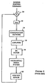
- FIG. 1 One such closed loop feedback system is shown in Figure 1, wherein a computer-generated desired-position command is compared with a trigonometric signal (explained below) by a digital comparator 10.
- the difference signal is converted to analog form at 12 and input to a compensation network 14 for filtering.
- the filtered signal is amplified at 16 and used to drive a DC motor 18 for positioning the media via, say, a rotating drum or roller.
- the media position is detected by a digital position sensor 20, which creates the trigonometric signal which was referred to above as one of the inputs to comparator 10.
- amplifier 16 may be a voltage drive or a current drive. If a voltage drive amplifier is chosen, inherent speed control is provided by the back electro-motive force of DC motor 18. The system lacks bandwidth due to mechanical and electrical parameters of voltage drive amplifier 16 and DC motor 18. That is, the system has limited positional resolution control related to the number of bits either at digital-to-analog converter 12 or at digital position sensor 20, whichever is lowest. Also, the quantization at digital-to-analog converter 12 creates compensation problems for compensation network 14 of the "feed forward" type.
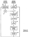
- This particular motion control loop utilizes a phase lock loop for the velocity control portion of the motion control loop. It has many of the same subsystems as the motion control loop of Figure 1, identified by primed reference numerals, but utilizes a phase detector 24, a switch 26, and a magnitude comparator 28 in place of the digital comparator 10 of Figure 1.
- this motion control loop of Figure 2 separates the position and velocity controls.
- Switch 26 will start in the position mode as illustrated while a desired position profile and feedback from digital position sensor 20' are compared at magnitude comparator 28.
- the state of switch 26 is changed to allow the velocity mode to take over, whereupon the phase detector 24 is used to provide an error signal for the motion control loop.
- the motion control loop provides ultra precision velocity control, but does not know where it is in absolute position space (an external counter could keep track of the digital position sensor 20' divisions but cannot provide control).
- the position portion of this motion control loop of Figure 2 still has the limiting capabilities described for the motion control loop of Figure 1.
- a media transport system for controlling the position and velocity of media in a document production apparatus marking engine having a media positioning system driven by a motor, includes a motion control loop to control the motor; a sensor adapted to detect the position of the media and to create a trigonometric signal characteristic of the position of the media; a resolver electronics subsystem adapted to trigonometrically process the trigonometric signal to create a resolved signal; and means for comparing the resolved signal to a reference clock signal to provide an error signal used to control the motor that drives the media positioning system.
- a media transport system for controlling the position and velocity of media in a document production apparatus marking engine having a media positioning system driven by a motor, includes a motion control loop to control the motor; a sensor adapted to detect the position of the media and to create a trigonometric signal characteristic of the position of the media, the trigonometric signal comprising frequency and phase components; a resolver electronics subsystem adapted to trigonometrically process the trigonometric signal to create a resolved signal; and means for comparing the resolved signal to a reference clock signal of predetermined frequency and phase to provide an error signal used to control the motor that drives the media positioning system.
- a method for controlling the position and velocity of media in a document production apparatus marking engine having a media positioning system driven by a motor includes detecting the position of the media; creating a trigonometric signal characteristic of the position of the media; trigonometrically processing the trigonometric signal to create a resolved signal; comparing the resolved signal to a reference clock signal to provide an error signal; and controlling the motor that drives the media positioning system with the error signal.
- a method for controlling the position and velocity of media in a document production apparatus marking engine having a media positioning system driven by a motor includes detecting the position of the media; creating a trigonometric signal characteristic of the position of the media, the trigonometric signal comprising frequency and phase components; trigonometrically processing the trigonometric signal to create a resolved signal; and comparing the resolved signal to a reference clock signal of predetermined frequency and phase to provide an error signal used to control the motor that drives the media positioning system.
- the trigonometric signal includes a sine portion and a cosine portion.
- the sine portion of the trigonometric signal is sin( ⁇ e *t+ ⁇ e ) and the cosine portion of the trigonometric signal is cos( ⁇ e *t+ ⁇ e ) ; where ⁇ e is the trigonometric signal frequency component, ⁇ e is the trigonometric signal phase component, and t is the time.
- the resolver electronics subsystem includes a first multiplier adapted to output the product of the sine portion of the trigonometric signal and a reference cosine command cos( ⁇ r *t+ ⁇ r ) ; a second multiplier adapted to output the product of cosine portion of the trigonometric signal and a reference sine command sin( ⁇ r *t+ ⁇ r ) , where ⁇ r is the frequency of the reference command and ⁇ r is the phase of the reference command; and means to add the outputs of the first and second multipliers.
- the present invention will be described in an environment of a thermal printer, although one skilled in the art will understand that the invention is useful in other types of document production apparatus.
- the invention is useful in other types of printers as well as in optical or digital copiers.
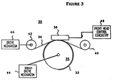
- Apparatus 30 comprises a receiver member 32, a dye carrier member 34, a rotatable drum 36, a thermal print head 38, a dye carrier member supply roller 40, a dye carrier member take-up roller 42, a drum drive mechanism 44, a roller drive mechanism 46, and print head control circuitry 48.
- Thermal print apparatus 30 is arranged to print color images on receiver member 32 from dyes transferred from the dye carrier member 34.
- Receiver member 32 in the form of a sheet of material such as paper, is secured to and positioned around a portion of rotatable drum 36 which is coupled to drum drive mechanism 44.
- drum drive mechanism 44 includes a motor (not shown) adapted to advance drum 36 and receiver member 32 under thermal print head 38.
- Thermal print head 38 has a plurality of thermal heating elements which press dye carrier member 34 against receiver member 32.
- Dye carrier member 34 is in the form of a web which is driven from supply roller 40 onto take-up roller 42 by roller drive mechanism 46 coupled to take-up roller 42.
- Drive mechanisms 44 and 46 each include a motor (not shown) which advance dye carrier member 34 and receiver member 32 relative to thermal print head 38.
- drive signals are continuously provided to drum drive mechanism 44 from, for example, a microcomputer (not shown) to rotate drum 36 and bring successive contiguous areas of receiver member 32 into the print region opposite the thermal heating element in thermal print head 38.
- a portion of a dye frame (not shown) containing a particular dye color on dye carrier member 34 is disposed between print head 38 and receiver member 32.
- Receiver member 32 and dye carrier member 34 are moved relative to the print head 38 during the printing operation.
- Energizing signals are provided to the thermal heating elements of thermal print head 38 by print head control circuitry 48 to selectively heat the thermal heating elements and cause dye from the particular dye frame to be transferred from dye carrier member 34 to receiver member 32.
- receiver member 32 moves through each print line of the print region opposite thermal print head 38, the selective energization of the thermal pixels results in printing of a color image on receiver member 32.
- the color of this image is determined by the color of the thermally transferable dye contained in the particular dye frame (not shown here but illustrated in Figure 3 of U.S. Patent No. 4,621,271) of dye carrier member 34 that is driven past the print region.
- dye carrier member 34 is advanced to move a frame of another dye color into position for printing.
- the thermal heating elements in print head 38 are selectively energized so as to print the next color frame of the image superimposed on the first printed color frame. This process is repeated until all of the different color frames needed to produce the desired image are superimposed on receiver member 32.
- Figure 4 illustrates this concept.
- subsystems which have similar counterparts in Figures 1 and/or 2 are identified by double-primed reference numerals.
- Digital position sensor 20'' detects the position of the media and creates a trigonometric signal, such as a sine signal sin( ⁇ e *t+ ⁇ e ) and a cosine signal cos( ⁇ e *t+ ⁇ e ) , where:
- resolver electronics subsystem 50 These outputs are trigonometrically processed by a resolver electronics subsystem 50.
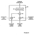
- the preferred embodiment of resolver electronics subsystem 50 is illustrated in Figure 5.
- the sine and cosine signals from digital position sensor 20'' are input to two multipliers 52, 54.
- Also input to multiplier 52 is a reference cosine command cos( ⁇ r *t+ ⁇ r )
- a reference sine command sin( ⁇ r *t+ ⁇ r ) is input to multiplier 54, where:
- the two resulting signals out of multipliers 52, 54 are then input to a summer 56.
- the output of summer 56 has the trigonometric form: sin( ⁇ e *t+ ⁇ e )*cos( ⁇ r *t+ ⁇ r ) + cos( ⁇ e *t+ ⁇ e )*sin( ⁇ r *t+ ⁇ r )
- sin(x+y) sin x cos y + cos x sin y
- equation (1) can be reduced to: sin[( ⁇ e + ⁇ r )*t+( ⁇ e + ⁇ r )]
- the sinusoidal output signal of the summer 56 is a resolved signal then sent to a conventional comparator 58 to drive the remainder of the motion control loop to provide high precision position resolution control and high precision ultra low velocity control.
- Comparator 58 transforms the sinusoidal type signal into a digital signal such as by conventional zero-crossover techniques.
- This digital signals is then input to phase detector 24'' ( Figure 4), where it is compared to a fixed reference clock of frequency ⁇ f radians/second and phase ⁇ f radians to provide an error signal.
- This error signal is input to compensation network 14'' for filtering.
- the filtered signal is amplified at 16'', and used to drive a motor 18'', such as a DC stepper motor, for positioning the media.
- the media position is detected by digital position sensor 20'', which creates the sine and cosine outputs referred to above as the input to resolver electronics 50.
- ⁇ e and ⁇ e will be controlled; thereby controlling the speed and position, respectively, of the mechanical/media system. Therefore, ⁇ e can be run as slow as the difference between ⁇ f and ⁇ r , and ⁇ e can be positioned as small as the difference between ⁇ f and ⁇ r. It also can be seen that bi-directional control is inherent if ⁇ f is larger than the range of ⁇ r . The same is true for ⁇ e .
- ⁇ e can only be controlled within one division of the digital position sensor 20''. Therefore, for a motion profile that requires a region of acceleration, followed by a region of constant velocity, and finally followed by a region of deceleration, the acceleration and deceleration regions must be accomplished in one division of the digital position sensor 20''.
- the present invention provides a media transport system having inherent bi-directional velocity control, high precision control at low velocities, and sub digital position sensor resolution position control.
- phase detector 24'' can be removed, but the loop looses bi-directional control, and becomes more difficult to control.
Landscapes
- Control Of Position Or Direction (AREA)
- Handling Of Sheets (AREA)
- Character Spaces And Line Spaces In Printers (AREA)
- Controlling Sheets Or Webs (AREA)
Claims (9)
- Transportsystem für Druckmedien zum Steuern der Lage und Geschwindigkeit der Medien (32, 34) in der Druckeinrichtung (30) eines Geräts zur Dokumentenherstellung, wobei die Druckeinrichtung folgende Komponenten aufweist: eine von einem Motor (18'') angetriebene Medienpositioniereinrichtung, einen Bewegungsregelkreis zur Steuerung des Motors, einen Sensor (20'') zur Erfassung der Lage des Mediums und Erzeugung eines trigonometrischen Signals, das die Lage des Mediums kennzeichnet, ein Resolverelektronik-Teilsystem (50) welches das trigonometrische Signal trigonometrisch verarbeitet, um ein aufgelöstes Signal mit einer Frequenzkomponente zu erzeugen,
gekennzeichnet durch einen Phasendetektor (24'') zum Vergleichen der Frequenzkomponente des aufgelösten Signals mit einem Referenztaktfrequenzsignal, um ein Fehlersignal zu erzeugen, das zur Steuerung des Motors verwendet wird, der die Medienpositioniereinrichtung antreibt. - Transportsystem nach Anspruch 1, in dem das Resolverelektronik-Teilsystem durch folgende Komponenten gekennzeichnet ist: einer ersten Multipliziereinrichtung, die das Produkt aus dem Sinusteil eines trigonometrischen Signals und einem Referenz-Cosinusbefehl abgibt; einer zweiten Multipliziereinrichtung, die das Produkt aus dem Cosinusteil des trigonometrischen Signals und einem Referenz-Sinusbefehl abgibt; und Mittel zum Addieren der Produktergebnisse der ersten und zweiten Multipliziereinrichtung.
- Transportsystem für Druckmedien zum Steuern der Lage und Geschwindigkeit der Medien in der Druckeinrichtung eines Geräts zur Dokumentenherstellung, wobei die Druckeinrichtung folgende Komponenten aufweist: eine von einem Motor angetriebene Medienpositioniereinrichtung, einen Bewegungsregelkreis zur Steuerung des Motors, einen Sensor zur Erfassung der Lage des Mediums und Erzeugung eines trigonometrischen Signals, das die Lage des Mediums kennzeichnet, ein Resolverelektronik-Teilsystem (50), welches das trigonometrische Signal trigonometrisch verarbeitet, um ein aufgelöstes Signal mit einer Frequenz- und Phasenkomponente zu erzeugen, gekennzeichnet durch einen Phasendetektor zum Vergleichen der Frequenz- und Phasenkomponente des aufgelösten Signals mit einem Referenztaktsignal, um ein Fehlersignal zu erzeugen, das zur Steuerung des Motors verwendet wird, der die Medienpositioniereinrichtung antreibt.
- Transportsystem nach Anspruch 3, in dem das Resolverelektronik-Teilsystem zusätzlich durch folgende Komponenten gekennzeichnet ist: einer ersten Multipliziereinrichtung, die das Produkt aus dem Sinusteil eines trigonometrischen Signals und einem Referenz-Cosinusbefehl abgibt; einer zweiten Multipliziereinrichtung, die das Produkt aus dem Cosinusteil des trigonometrischen Signals und einem Referenz-Sinusbefehl abgibt; und Mittel zum Addieren der Produktergebnisse der ersten und zweiten Multipliziereinrichtung.
- Transportsystem nach Anspruch 3, dadurch gekennzeichnet, daß der Sinusteil des trigonometrischen Signals


- Transportsystem nach Anspruch 5, dadurch gekennzeichnet, daß das Resolverelektronik-Teilsystem Multiplikatormittel zum Multiplizieren des Sinusteils des trigonometrischen Signals mit einem Referenz-Cosinusbefehl


- Transportsystem nach Anspruch 3, dadurch gekennzeichnet, daß das Referenz-Taktsignal eine feststehende Frequenz und Phase aufweist.
- Transportsystem nach Anspruch 3, dadurch gekennzeichnet, daß das Gerät zur Dokumentenherstellung ein Farbdrucker mit Mitteln zum Positionieren und Neupositionieren von Druckmedien in einer Druckstation ist, um aufeinanderfolgende Farbebenen in exakter Ausrichtung zu drucken.
- Transportsystem nach Anspruch 3, dadurch gekennzeichnet, daß das Gerät zur Dokumentenherstellung ein Thermodrucker ist.
Applications Claiming Priority (2)
| Application Number | Priority Date | Filing Date | Title |
|---|---|---|---|
| US127844 | 1993-09-28 | ||
| US08/127,844 US5446355A (en) | 1993-09-28 | 1993-09-28 | Media transport system with high precision position and speed control |
Publications (2)
| Publication Number | Publication Date |
|---|---|
| EP0645332A1 EP0645332A1 (de) | 1995-03-29 |
| EP0645332B1 true EP0645332B1 (de) | 1997-02-26 |
Family
ID=22432255
Family Applications (1)
| Application Number | Title | Priority Date | Filing Date |
|---|---|---|---|
| EP94114889A Expired - Lifetime EP0645332B1 (de) | 1993-09-28 | 1994-09-21 | Transportvorrichtung für Druckerzeugnisse mit sehr genauer Positions- und Geschwindigkeitssteuerung |
Country Status (4)
| Country | Link |
|---|---|
| US (1) | US5446355A (de) |
| EP (1) | EP0645332B1 (de) |
| JP (1) | JP3411104B2 (de) |
| DE (1) | DE69401797T2 (de) |
Families Citing this family (5)
| Publication number | Priority date | Publication date | Assignee | Title |
|---|---|---|---|---|
| US5703455A (en) * | 1995-09-05 | 1997-12-30 | Ricoh Company, Ltd. | Control device for a stepping motor included in an electronic apparatus |
| US5764018A (en) * | 1995-09-29 | 1998-06-09 | Hewlett-Packard Co. | Hysteresis removal for positioning systems with variable backlash and stiction |
| DE19742801A1 (de) * | 1997-09-27 | 1999-04-08 | Stegmann Max Antriebstech | Verfahren und Vorrichtung zur Übertragung von Prozeßinformationen für geregelte Antriebe |
| US5980139A (en) * | 1998-04-24 | 1999-11-09 | Lexmark International, Inc. | Method of speed control for imaging system including printers with intelligent options |
| US6064171A (en) * | 1999-06-11 | 2000-05-16 | Lexmark, International, Inc. | Host based stepper motor phase controller and method therefor |
Family Cites Families (8)
| Publication number | Priority date | Publication date | Assignee | Title |
|---|---|---|---|---|
| GB1527741A (en) * | 1975-03-25 | 1978-10-11 | Rca Corp | Brushless dc motor rotation control |
| GB2137966B (en) * | 1983-04-13 | 1986-06-18 | De La Rue Syst | Sheet feeding apparatus |
| US4701839A (en) * | 1984-11-09 | 1987-10-20 | International Cybernetic Corporation | Sampled data servo control system with field orientation |
| GB8812893D0 (en) * | 1988-05-31 | 1988-07-06 | De La Rue Syst | Apparatus for sensing sheets |
| US4906909A (en) * | 1989-04-28 | 1990-03-06 | The United States Of America As Represented By The Secretary Of The Navy | Analog electronic control differential transmitter |
| US4962331A (en) * | 1989-07-13 | 1990-10-09 | Servo-Tek Products Company, Inc. | Rotatable control signal generator |
| EP0451321B1 (de) * | 1990-04-13 | 1995-04-12 | Graphtec Kabushiki Kaisha | Einrichtung zum Steuern der Papierlage in einem Registrierapparat |
| US5072179A (en) * | 1990-06-12 | 1991-12-10 | At&T Bell Laboratories | High resolution one and two dimensional position indicating apparatus with plural windings having a common connection and separately energized by signals of different phase |
-
1993
- 1993-09-28 US US08/127,844 patent/US5446355A/en not_active Expired - Lifetime
-
1994
- 1994-09-21 EP EP94114889A patent/EP0645332B1/de not_active Expired - Lifetime
- 1994-09-21 DE DE69401797T patent/DE69401797T2/de not_active Expired - Fee Related
- 1994-09-27 JP JP23176694A patent/JP3411104B2/ja not_active Expired - Fee Related
Also Published As
| Publication number | Publication date |
|---|---|
| US5446355A (en) | 1995-08-29 |
| DE69401797T2 (de) | 1997-08-28 |
| EP0645332A1 (de) | 1995-03-29 |
| JP3411104B2 (ja) | 2003-05-26 |
| DE69401797D1 (de) | 1997-04-03 |
| JPH07164693A (ja) | 1995-06-27 |
Similar Documents
| Publication | Publication Date | Title |
|---|---|---|
| EP0884192B1 (de) | Druckvorrichtung für Endlospapier | |
| EP0180911A1 (de) | Kontrollmethode und Kontrollgerät für einen Farbdrucker | |
| EP0280699B1 (de) | Präzisionspapiertransportsystem | |
| US4893951A (en) | Ink ribbon positioning system for color printing apparatus | |
| AU672525B2 (en) | High speed media management device | |
| CN103862863A (zh) | 通过使用带表面速度测量调节打印频率来改善图像质量 | |
| EP0645332B1 (de) | Transportvorrichtung für Druckerzeugnisse mit sehr genauer Positions- und Geschwindigkeitssteuerung | |
| JPH0564112B2 (de) | ||
| US5610721A (en) | Image forming apparatus for forming an image in synchronization with a vertical synchronizing signal | |
| EP0584792A2 (de) | Blattzuführapparat | |
| US5218380A (en) | Platen drag mechanism for thermal printers | |
| EP0535213B1 (de) | Positionssteuerungsgerät für die übertragungstrommel in einem elektrostatografischen druck-/kopiergerät | |
| US5159356A (en) | Web printing apparatus | |
| EP0881081A2 (de) | Serielles Thermisches Aufzeichnungsgerät | |
| EP0987117A2 (de) | Programmierbare Getriebesteuerung einer Führungsspindel für einen Druckkopf mit variabler Anzahl von Kanälen | |
| EP0983864A3 (de) | Druckkopfbewegungssteuerverfahren auf Basis der Gewindesteigung in einer Spindel zur Minimierung des Fehlers von Druckgang zu Druckgang in einem Bildverarbeitungsgerät | |
| GB2282567A (en) | Multi-ribbon printer | |
| US6020907A (en) | Simplified printer drive mechanism | |
| JPH04305469A (ja) | 感熱記録装置 | |
| EP0300825B1 (de) | Wandler zur Feststellung des Papiervoschubs für Drucker oder Plotter | |
| JPH0696300B2 (ja) | カラ−記録装置 | |
| EP1402719A1 (de) | Bandsteuervorrichtung für ein bilderzeugungsgerät | |
| JP2019156632A (ja) | 回転体制御装置、搬送装置、画像形成装置、回転体制御方法、回転体制御プログラム | |
| JP2921142B2 (ja) | 定位置操作装置 | |
| JPS60183164A (ja) | プリンタのシヤトル機構 |
Legal Events
| Date | Code | Title | Description |
|---|---|---|---|
| PUAI | Public reference made under article 153(3) epc to a published international application that has entered the european phase |
Free format text: ORIGINAL CODE: 0009012 |
|
| AK | Designated contracting states |
Kind code of ref document: A1 Designated state(s): DE FR GB |
|
| 17P | Request for examination filed |
Effective date: 19950913 |
|
| GRAG | Despatch of communication of intention to grant |
Free format text: ORIGINAL CODE: EPIDOS AGRA |
|
| 17Q | First examination report despatched |
Effective date: 19960614 |
|
| GRAH | Despatch of communication of intention to grant a patent |
Free format text: ORIGINAL CODE: EPIDOS IGRA |
|
| GRAH | Despatch of communication of intention to grant a patent |
Free format text: ORIGINAL CODE: EPIDOS IGRA |
|
| GRAA | (expected) grant |
Free format text: ORIGINAL CODE: 0009210 |
|
| AK | Designated contracting states |
Kind code of ref document: B1 Designated state(s): DE FR GB |
|
| REF | Corresponds to: |
Ref document number: 69401797 Country of ref document: DE Date of ref document: 19970403 |
|
| ET | Fr: translation filed | ||
| PLBE | No opposition filed within time limit |
Free format text: ORIGINAL CODE: 0009261 |
|
| STAA | Information on the status of an ep patent application or granted ep patent |
Free format text: STATUS: NO OPPOSITION FILED WITHIN TIME LIMIT |
|
| 26N | No opposition filed | ||
| PGFP | Annual fee paid to national office [announced via postgrant information from national office to epo] |
Ref country code: GB Payment date: 19980806 Year of fee payment: 5 |
|
| PGFP | Annual fee paid to national office [announced via postgrant information from national office to epo] |
Ref country code: FR Payment date: 19980902 Year of fee payment: 5 |
|
| PGFP | Annual fee paid to national office [announced via postgrant information from national office to epo] |
Ref country code: DE Payment date: 19980928 Year of fee payment: 5 |
|
| PG25 | Lapsed in a contracting state [announced via postgrant information from national office to epo] |
Ref country code: GB Free format text: LAPSE BECAUSE OF NON-PAYMENT OF DUE FEES Effective date: 19990921 |
|
| GBPC | Gb: european patent ceased through non-payment of renewal fee |
Effective date: 19990921 |
|
| PG25 | Lapsed in a contracting state [announced via postgrant information from national office to epo] |
Ref country code: FR Free format text: LAPSE BECAUSE OF NON-PAYMENT OF DUE FEES Effective date: 20000531 |
|
| PG25 | Lapsed in a contracting state [announced via postgrant information from national office to epo] |
Ref country code: DE Free format text: LAPSE BECAUSE OF NON-PAYMENT OF DUE FEES Effective date: 20000701 |
|
| REG | Reference to a national code |
Ref country code: FR Ref legal event code: ST |