EP0645462A1 - Verfahren zur Optimierung der Eigenspannungsverteilung in Federelementen - Google Patents
Verfahren zur Optimierung der Eigenspannungsverteilung in Federelementen Download PDFInfo
- Publication number
- EP0645462A1 EP0645462A1 EP94113265A EP94113265A EP0645462A1 EP 0645462 A1 EP0645462 A1 EP 0645462A1 EP 94113265 A EP94113265 A EP 94113265A EP 94113265 A EP94113265 A EP 94113265A EP 0645462 A1 EP0645462 A1 EP 0645462A1
- Authority
- EP
- European Patent Office
- Prior art keywords
- predetermined strength
- shot peening
- compression springs
- section
- helical compression
- Prior art date
- Legal status (The legal status is an assumption and is not a legal conclusion. Google has not performed a legal analysis and makes no representation as to the accuracy of the status listed.)
- Granted
Links
- 238000000034 method Methods 0.000 title claims abstract description 26
- 238000009826 distribution Methods 0.000 title claims abstract description 9
- 230000008569 process Effects 0.000 title claims description 8
- 230000006835 compression Effects 0.000 claims abstract description 20
- 238000007906 compression Methods 0.000 claims abstract description 20
- 238000005480 shot peening Methods 0.000 claims abstract description 20
- 238000004519 manufacturing process Methods 0.000 claims abstract description 10
- 239000000725 suspension Substances 0.000 claims abstract 2
- 238000001816 cooling Methods 0.000 claims 1
- 238000010438 heat treatment Methods 0.000 claims 1
- 230000006872 improvement Effects 0.000 abstract description 3
- 238000005422 blasting Methods 0.000 description 21
- 238000005457 optimization Methods 0.000 description 3
- 238000005452 bending Methods 0.000 description 2
- 230000008859 change Effects 0.000 description 2
- 230000000694 effects Effects 0.000 description 2
- 230000005855 radiation Effects 0.000 description 2
- 238000005496 tempering Methods 0.000 description 2
- 230000001609 comparable effect Effects 0.000 description 1
- 238000011161 development Methods 0.000 description 1
- 230000018109 developmental process Effects 0.000 description 1
- 238000002360 preparation method Methods 0.000 description 1
- 230000009467 reduction Effects 0.000 description 1
- 230000002040 relaxant effect Effects 0.000 description 1
- 238000007493 shaping process Methods 0.000 description 1
- 230000036962 time dependent Effects 0.000 description 1
Images
Classifications
-
- F—MECHANICAL ENGINEERING; LIGHTING; HEATING; WEAPONS; BLASTING
- F16—ENGINEERING ELEMENTS AND UNITS; GENERAL MEASURES FOR PRODUCING AND MAINTAINING EFFECTIVE FUNCTIONING OF MACHINES OR INSTALLATIONS; THERMAL INSULATION IN GENERAL
- F16F—SPRINGS; SHOCK-ABSORBERS; MEANS FOR DAMPING VIBRATION
- F16F1/00—Springs
- F16F1/02—Springs made of steel or other material having low internal friction; Wound, torsion, leaf, cup, ring or the like springs, the material of the spring not being relevant
- F16F1/04—Wound springs
- F16F1/06—Wound springs with turns lying in cylindrical surfaces
-
- F—MECHANICAL ENGINEERING; LIGHTING; HEATING; WEAPONS; BLASTING
- F16—ENGINEERING ELEMENTS AND UNITS; GENERAL MEASURES FOR PRODUCING AND MAINTAINING EFFECTIVE FUNCTIONING OF MACHINES OR INSTALLATIONS; THERMAL INSULATION IN GENERAL
- F16F—SPRINGS; SHOCK-ABSORBERS; MEANS FOR DAMPING VIBRATION
- F16F1/00—Springs
- F16F1/02—Springs made of steel or other material having low internal friction; Wound, torsion, leaf, cup, ring or the like springs, the material of the spring not being relevant
-
- C—CHEMISTRY; METALLURGY
- C21—METALLURGY OF IRON
- C21D—MODIFYING THE PHYSICAL STRUCTURE OF FERROUS METALS; GENERAL DEVICES FOR HEAT TREATMENT OF FERROUS OR NON-FERROUS METALS OR ALLOYS; MAKING METAL MALLEABLE, e.g. BY DECARBURISATION OR TEMPERING
- C21D7/00—Modifying the physical properties of iron or steel by deformation
- C21D7/02—Modifying the physical properties of iron or steel by deformation by cold working
- C21D7/04—Modifying the physical properties of iron or steel by deformation by cold working of the surface
- C21D7/06—Modifying the physical properties of iron or steel by deformation by cold working of the surface by shot-peening or the like
-
- C—CHEMISTRY; METALLURGY
- C21—METALLURGY OF IRON
- C21D—MODIFYING THE PHYSICAL STRUCTURE OF FERROUS METALS; GENERAL DEVICES FOR HEAT TREATMENT OF FERROUS OR NON-FERROUS METALS OR ALLOYS; MAKING METAL MALLEABLE, e.g. BY DECARBURISATION OR TEMPERING
- C21D9/00—Heat treatment, e.g. annealing, hardening, quenching or tempering, adapted for particular articles; Furnaces therefor
- C21D9/02—Heat treatment, e.g. annealing, hardening, quenching or tempering, adapted for particular articles; Furnaces therefor for springs
-
- Y—GENERAL TAGGING OF NEW TECHNOLOGICAL DEVELOPMENTS; GENERAL TAGGING OF CROSS-SECTIONAL TECHNOLOGIES SPANNING OVER SEVERAL SECTIONS OF THE IPC; TECHNICAL SUBJECTS COVERED BY FORMER USPC CROSS-REFERENCE ART COLLECTIONS [XRACs] AND DIGESTS
- Y10—TECHNICAL SUBJECTS COVERED BY FORMER USPC
- Y10S—TECHNICAL SUBJECTS COVERED BY FORMER USPC CROSS-REFERENCE ART COLLECTIONS [XRACs] AND DIGESTS
- Y10S148/00—Metal treatment
- Y10S148/902—Metal treatment having portions of differing metallurgical properties or characteristics
- Y10S148/908—Spring
Definitions
- the present invention relates to a method according to the preamble of patent claim 1.
- an internal stress distribution is considered to be optimal, in which the resulting load stress in the finished spring in the most highly stressed cross-section does not reach the compressive or tensile yield point in any point of the cross-section and a critical tensile stress value of 200 N / mm2 in the edge area near the surface is not exceeded.
- the setting or plasticizing of springs means the initial loading of springs after shaping and tempering, at which the yield point of the material, depending on the type of spring and stress, is exceeded in some areas of the spring cross-section.
- the ratio of the plasticized cross-sectional area to the total cross-section also referred to as degree of plasticization P, in conjunction with the material-specific yield point, determines the height and distribution of the residual stresses induced by the setting process.
- the internal stress can be influenced both in terms of its height and its distribution in the sense of optimization.
- the invention is based on the object of providing a method of the type mentioned at the outset which permits a further improvement in the service life of, in particular, helical compression springs with strengths of R m ⁇ 1,800 N / mm2.
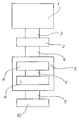
- the present method assumes that the helical compression springs with a residual heat remaining from the preceding manufacturing steps 1 such as hardening, tempering or relaxing are fed to a setting press 2 via a transport path 3 the helical compression springs are transported immediately after the setting process via a transport path 4 into a shot peening system 5, the peening device 5 consisting of at least two mutually independent blasting chambers 6 and 8, which are connected via a transport route 7, the transport routes 3 and 4 before and between the production zones setting press 2 or shot peening system 5 are designed so that the helical compression spring can be heated or cooled to a predetermined temperature.
- the decisive factor here is that the type of temperature control produces a temperature or strength profile prescribed for the subsequent production step in the cross-section of the helical compression spring.
- the shot peening treatment in the first shot peening chamber 6 is usually carried out as preconditioning of the helical compression spring for the final shot peening treatment in the second shot blasting chamber 8, which is equipped with all the necessary devices for the tension blasting of helical compression springs.
- Preconditioning means all measures which in particular increase the depth effect of shot peening.
- the coil springs are fed to the finishing line 10 via a transport path 9.
- the spring element is fed to the first blasting chamber 6 via the transport path 4 with a temperature or strength profile depending on the material subjected to the blasting treatment.
- Shot peening insofar as it is hot blasting, is not used as an alternative to tension blasting as described in US Pat. No. 3,205,556, to minimize the shape and shape changes of the spring caused by the tension blasting, but as a useful addition and preparation of stress radiation.
- the helical compression springs are fed via the transport path 7 to the second blasting chamber 8, in which the helical compression springs are pretensioned to a predetermined length or a predetermined load, and are subjected to a shot peening treatment in the pretensioned state.
- the helical compression springs In order to ensure that radiation is as uniform as possible on all sides, the helical compression springs must be rotated or oscillated about their central axis in the "hot spot" area of the shot peening time-dependent cycle sequence as well as in a continuous cycle.
Landscapes
- Engineering & Computer Science (AREA)
- Chemical & Material Sciences (AREA)
- Mechanical Engineering (AREA)
- General Engineering & Computer Science (AREA)
- Crystallography & Structural Chemistry (AREA)
- Materials Engineering (AREA)
- Metallurgy (AREA)
- Organic Chemistry (AREA)
- Physics & Mathematics (AREA)
- Thermal Sciences (AREA)
- Springs (AREA)
- Crystals, And After-Treatments Of Crystals (AREA)
- Vehicle Body Suspensions (AREA)
- Heat Treatment Of Articles (AREA)
- Optical Communication System (AREA)
- Led Device Packages (AREA)
Abstract
Description
- Die vorliegende Erfindung betrifft ein Verfahren nach dem Oberbegriff des Patentanspruchs 1.
- Als optimal wird in diesem Zusammenhang eine Eigenspannungsverteilung angesehen, bei der in der fertigen Feder im höchstbelasteten Querschnitt die resultierende Lastspannung in keinem Punkt des Querschnittes die Druck- bzw. Zugfließgrenze erreicht und ein kritischer Zugspannungswert von 200 N/mm² im oberflächennahen Randbereich nicht überschritten wird.
- Nach dem Stand der Technik kommen zur gezielten Beeinflussung der Eigenspannungen in Federelementen in erster Linie zwei Verfahren, das Setzen und das Kugelstrahlen zur Anwendung, welche die Eigenspannungsverteilung primär in bestimmten, den unterschiedlichen Verfahren zugeordneten Querschnittsbereichen verändern. Unter dem Setzen bzw. Plastizieren von Federn versteht man, die Erstbelastung von Federn nach Formgebung und Vergütung, bei der die Fließgrenze des Werkstoffes, abhängig von Feder- und Beanspruchsart, in Teilbereichen des Federquerschnittes überschritten wird.
- Das Verhältnis der plastizierten Querschnittsfläche zum Gesamtquerschnitt, auch als Plastizierungsgrad P bezeichnet, bestimmt in Verbindung mit der werkstoffspezifischen Fließgrenze Höhe und Verteilung der durch den Setzvorgang induzierten Eigenspannungen.
- Durch lokal begrenzte Änderung der Fließgrenze, hervorgerufen durch die Vorgabe eines bestimmten Festigkeits- oder Temperaturprofiles im Querschnitt der Feder während des Setzvorganges, kann daher die Eigenspannung sowohl in ihrer Höhe als auch in ihrer Verteilung im Sinne einer Optimierung gezielt beeinflußt werden.
- Während beim Setzen die Eigenspannungen über den gesamten Querschnitt, abhängig von der Beanspruchungsart, einachsig bei Biegung oder zweiachsig bei Torsion, und von der Beanspruchungsrichtung, Zug oder Druck, gerichteten Änderungen unterworfen sind, ist die Beeinflussungszone des Querschnitts beim Kugelstrahlen im wesentlichen auf die oberflächennahen Randbereiche beschränkt, wobei unabhängig von Feder- und Beanspruchungsart eine orthogonale Spannungsverteilung in der Randschicht erzeugt wird.
- In der US-PS 2 608 752 wird am Beispiel einer Einblattfeder ein Verfahren beschrieben, bei welchem die Zugseite einer Blattfeder unter Vorspannung (60 % bis 100 % Re) kugelgestrahlt wird. Das Verfahren ist unter der Bezeichnung "Spannungsstrahlen" in der Praxis eingeführt und wird für Einblatt- und Parabelfedern heute weltweit in vielen Varianten angewendet.
- Maschinen und Vorrichtungen zum Spannungsstrahlen von Blattfedern sowie einige Verfahrensvarianten sind in der US-PS 3 094 768 und GB-PS 959 801 beschrieben.
- Als Alternative zum Spannungsstrahlen, mit vergleichbarer Wirkung ohne den Nachteil der relativ großen Formänderung, wird in der US-PS 3 205 556 ein Strahlverfahren beschrieben, bei dem die Blattfedern unbelastet (d.h. ohne Vorspannung), jedoch mit erhöhter Temperatur (150 °C bis 350 °C) kugelgestrahlt werden. Dieses im folgenden als "Warmstrahlen" bezeichnete Verfahren hat sich bisher in der Praxis nicht durchsetzen können. Begründet ist dies einmal dadurch, daß die größeren Formänderungen beim Spannungsstrahlen bei Neuentwicklungen einfach durch entsprechende Vorgaben für die Biegewerkzeuge kompensiert werden können und zum anderen, daß die lebensdauersteigernde Wirkung des Warmstrahlens in der Regel wesentlich niedriger ist als beim Spannungsstrahlen.
- Gemeinsam ist allen zuvor genannten Druckschriften, daß die beispielhaft genannten Anwendungen ausschließlich Blattfedern als Federelemente, mit im wesentlichen einachsiger Beanspruchung betreffen.
- Die hierfür gültigen Aussagen zur Verbesserung der Lebensdauer können, inbesondere im Hinblick auf die Reihenfolge der einzelnen Fertigungsschritte und eine Optimierung der Eigenspannungsverteilung, auf torsionsbeanspruchte Federelemente nicht übertragen werden, ohne die im wesentlichen zweiachsige Beanspruchung zu berücksichtigen.
- Ferner ist zum Beispiel aus "Warmgeformte Federn", Hoesch Hohenlimburg AG, 1987, Seiten 189 bis 1991 das Setzen und nachfolgende Kugelstrahlen von Schraubendruckfedern bekannt.
- Der Erfindung liegt nunmehr die Aufgabe zugrunde, ein Verfahren der eingangs.genannten Art zu schaffen, das eine weitere Verbesserung der Lebensdauer von insbesondere Schraubendruckfedern mit Festigkeiten von Rm ≧ 1.800 N/mm² erlaubt.
- Diese Aufgabe wird durch die im kennzeichnenden Teil des Patentanspruches 1 angegebenen Merkmale gelöst.
- Vorteilhafte und zweckmäßige Verfahrensschritte des erfindungsgemäßen Verfahrens sind in den Ansprüchen 2 bis 7 angegeben.
- Die Vorteile des erfindungsgemäßen Verfahrens liegen insbesondere darin, daß je nach Zielsetzung der Optimierung eine Erhöhung der Lebensdauer der Schraubendruckfedern oder eine Reduzierung des Federgewichts erreicht wird.
- Anhand der schematischen Zeichung wird das erfindungsgemäße Verfahren im folgenden näher erläutert.
- Unabhängig davon, ob Federelemente warm, kalt oder halbwarm geformt werden, geht das vorliegende Verfahren davon aus, daß die Schraubendruckfedern mit einer aus den vorangehenden Fertigungsschritten 1 wie Härten, Anlassen bzw. Entspannen verbliebenen Restwärme einer Setzpresse 2 über eine Transportstrecke 3 zugeführt werden, von der die Schraubendruckfedern unmittelbar nach dem Setzvorgang über eine Transportstrecke 4 in eine Kugelstrahlanlage 5 weitertransportiert werden, wobei die Kugelstrahlanlage 5 aus mindestens zwei voneinander unabhängigen Strahlenkammern 6 und 8, die über eine Transportstrecke 7 verbunden sind, besteht, wobei die Transportstrecken 3 und 4 vor und zwischen den Fertigungszonen Setzpresse 2 bzw. Kugelstrahlanlage 5 so ausgeführt sind, daß die Schraubendruckfeder auf eine vorgegebene Temperatur erwärmt bzw. abgekühlt werden kann. Entscheidend hierbei ist, daß durch die Art der Temperierung ein für den nachfolgenden Fertigungsschritt vorgeschriebenes Temperatur- bzw. Festigkeitsprofil im Stabquerschnitt der Schraubendruckfeder erzeugt wird.
- Die Kugelstrahlbehandlung in der ersten Strahlkammer 6 erfolgt in der Regel als Vorkonditionierung der Schraubendruckfeder für die abschließende Kugelstrahlbehandlung in der zweiten Strahlkammer 8, welche mit allen notwendigen Einrichtungen für das Spannungsstrahlen von Schraubendruckfedern ausgerüstet ist.
- Unter Vorkonditionierung sind hier alle Maßnahmen zu verstehen, die insbesondere die Tiefenwirkung der Kugelstrahlbehandlung erhöhen.
- Nach der Kugelstrahlbehandlung in der zweiten Strahlkammer 8 werden die Schraubenfedern über eine Transportstrecke 9 der Endfertigung 10 zugeführt.
- Neben den üblichen Standardmaßnahmen wie der Erhöhung der Strahlenergie (mV²/2) durch Vergrößerung der Strahlmittelgeschwindigkeit und/oder der Strahlmittelmasse insbesondere des Kornduchmessers, wird das Federelement der ersten Strahlkammer 6 über die Transportstrecke 4 mit einem vom Werkstoff abhängigen Temperatur- bzw. Festigkeitsprofil zugeführt und der Strahlbehandlung unterzogen.
- Das Kugelstrahlen wird hierbei, sofern es sich um ein Warmstrahlen handelt, nicht wie in der US-PS 3 205 556 beschrieben als Alternative zum Spannungsstrahlen, zur Minimierung der durch das Spannungsstrahlen hervorgerufenen Form- und Gestaltänderungen der Feder angewendet, sondern als sinnvolle Ergänzung und Vorbereitung des Spannungsstrahlens.
- Die Schraubendruckfedern werden nach der Kugelstrahlbehandlung in der ersten Strahlkammer 6 über die Transportstrecke 7 der zweiten Strahlkammer 8 zugeführt, in der die Schraubendruckfedern auf eine vorgegebene Länge oder eine vorgegebene Last vorgespannt werden, und im vorgespannten Zustand einer Kugelstrahlbehandlung ausgesetzt.
- Um eine allseitige, möglichst gleichmäßige Bestrahlung sicherzustellen, müssen die Schraubendruckfedern um ihre Mittelachse rotierend oder oszillierend in den "Hot-Spot""-Bereich des Kugelstrahls bewegt werden. Dies kann sowohl in einer zeitabhängigen Taktfolge als auch in einem kontinuierlichen Durchlauf geschehen.
Claims (7)
- Verfahren zur Optimierung der Eigenspannungsverteilung in Federelementen, die als Fahrzeugtragfedern dienen, insbesondere im Stabquerschnitt von Schraubendruckfedern höherer Festigkeit, wobei die Schraubendruckfedern gesetzt und kugelgestrahlt werden, dadurch gekennzeichnet, daß die Schraubendruckfedern den Fertigungsschritten Setzen und Kugelstrahlen mit einem vorgegebenen, auf den Stabquerschnitt bezogenen Festigkeitsprofil zugeführt werden.
- Verfahen nach Anspruch 1, dadurch gekennzeichnet, daß das vorgegebene, auf den Stabquerschnitt bezogene Festigkeitsprofil temporär, vor dem Setzen bzw. Kugelstrahlen durch eine gezielte Erwarmung oder Abkühlung erzeugt wird.
- Verfahren nach Anspruch 1, dadurch gekennzeichnet, daß das vorgegebene, auf den Stabquerschnitt bezogene Festigkeitsprofil permanent, durch geeignete Fertigungsschritte vor dem Setzen und Kugelstrahlen erzeugt wird und bei Raumtemperatur vorliegt.
- Verfahren nach Anspruch 1, dadurch gekennzeichnet, daß das vorgegebene Festigkeitsprofil vor dem Setzen unterschiedlich ist zu dem vorgegebenen Festigkeitsprofil vor dem Kugelstrahlen.
- Fertigungsverfahren nach einem oder mehreren der Ansprüche 1 bis 4, dadurch gekennzeichnet, daß das vorgegebene Festigkeitsprofil über die Stablänge annähernd konstant gehalten wird.
- Verfahren nach einem oder mehreren der Ansprüche 1 bis 4, dadurch gekennzeichnet, daß das vorgegebene Festigkeitsprofil über die Stablänge nicht konstant ist.
- Verfahren nach einem oder mehreren der Ansprüche 1 bis 6, dadurch gekennzeichnet, daß den Fertigungsschritten Setzen und Kugelstrahlen der Fertigungsschritt Spannungsstrahlen nachgeschaltet wird.
Applications Claiming Priority (2)
| Application Number | Priority Date | Filing Date | Title |
|---|---|---|---|
| DE4330832A DE4330832C2 (de) | 1993-09-11 | 1993-09-11 | Verfahren zur Optimierung der Eigenspannungsverteilung im Stabquerschnitt von Schraubendruckfedern |
| DE4330832 | 1993-09-11 |
Publications (2)
| Publication Number | Publication Date |
|---|---|
| EP0645462A1 true EP0645462A1 (de) | 1995-03-29 |
| EP0645462B1 EP0645462B1 (de) | 2001-06-13 |
Family
ID=6497444
Family Applications (1)
| Application Number | Title | Priority Date | Filing Date |
|---|---|---|---|
| EP94113265A Expired - Lifetime EP0645462B1 (de) | 1993-09-11 | 1994-08-25 | Verfahren zur Optimierung der Eigenspannungsverteilung in Federelementen |
Country Status (12)
| Country | Link |
|---|---|
| US (1) | US5534088A (de) |
| EP (1) | EP0645462B1 (de) |
| JP (1) | JPH07217683A (de) |
| KR (1) | KR0149711B1 (de) |
| AT (1) | ATE202154T1 (de) |
| AU (1) | AU672522B2 (de) |
| BR (1) | BR9403489A (de) |
| CA (1) | CA2131732C (de) |
| DE (2) | DE4330832C2 (de) |
| ES (1) | ES2074409T3 (de) |
| PT (1) | PT645462E (de) |
| ZA (1) | ZA946892B (de) |
Cited By (1)
| Publication number | Priority date | Publication date | Assignee | Title |
|---|---|---|---|---|
| CN111235361A (zh) * | 2018-11-29 | 2020-06-05 | 永嘉县三和弹簧有限公司 | 一种自动弹簧热压机 |
Families Citing this family (7)
| Publication number | Priority date | Publication date | Assignee | Title |
|---|---|---|---|---|
| US6022427A (en) * | 1997-02-08 | 2000-02-08 | Fried Krupp | Method for producing helical springs |
| DE19814299A1 (de) * | 1998-03-31 | 1999-10-07 | Volkswagen Ag | Verfahren zum Bearbeiten eines Werkstücks aus Metall |
| ATE235567T1 (de) * | 1998-10-02 | 2003-04-15 | Thyssen Krupp Automotive Ag | Verfahren zum herstellen von schraubenfedern |
| DE19937407A1 (de) * | 1999-08-07 | 2001-02-08 | Bayerische Motoren Werke Ag | Verfahren zum Einstellen der Federvorspannung einer Ventil-Feder |
| DE10027541A1 (de) * | 2000-06-02 | 2001-12-13 | Eurocopter Deutschland | Verfahren zur Herstellung eines Metallbalges aus hochfestem Werkstoff |
| CN103387114B (zh) * | 2013-08-07 | 2015-10-28 | 兖州煤业股份有限公司 | 一种采煤工作面前部刮板运输机溜槽安装装置 |
| KR101749039B1 (ko) | 2015-06-29 | 2017-06-21 | 부경대학교 산학협력단 | 축제식 새우 양식을 위한 바이오플락 배양장치 |
Citations (4)
| Publication number | Priority date | Publication date | Assignee | Title |
|---|---|---|---|---|
| US2351726A (en) * | 1940-07-11 | 1944-06-20 | Eaton Mfg Co | Coil spring |
| GB959801A (en) * | 1960-04-20 | 1964-06-03 | Rockwell Standard Co | Spring leaf and method for making |
| US3661655A (en) * | 1970-11-17 | 1972-05-09 | North American Rockwell | Metallic articles and the manufacture thereof |
| US5225008A (en) * | 1991-11-18 | 1993-07-06 | Nhk Spring Co., Ltd. | Method for manufacturing a high-strength spring |
Family Cites Families (6)
| Publication number | Priority date | Publication date | Assignee | Title |
|---|---|---|---|---|
| SU621760A1 (ru) * | 1976-03-09 | 1978-08-30 | Efimov Viktor Petrovich | Способ упрочнени винтовых пружин |
| JPS58123825A (ja) * | 1982-01-20 | 1983-07-23 | Kawasaki Steel Corp | 無方向性電磁鋼板の製造方法 |
| CA2002138C (en) * | 1988-11-08 | 1999-12-14 | Susumu Yamamoto | High-strength coil spring and method of producing same |
| JP3009452B2 (ja) * | 1990-11-21 | 2000-02-14 | 中央発條株式会社 | 高強度浸炭窒化処理コイルばねの製造方法 |
| DE4124326C1 (de) * | 1991-07-23 | 1992-04-16 | Krupp Brueninghaus Gmbh, 5980 Werdohl, De | |
| JP2994508B2 (ja) * | 1991-11-26 | 1999-12-27 | 株式会社東郷製作所 | コイルばねの製造方法 |
-
1993
- 1993-09-11 DE DE4330832A patent/DE4330832C2/de not_active Expired - Lifetime
-
1994
- 1994-08-25 DE DE59409782T patent/DE59409782D1/de not_active Expired - Lifetime
- 1994-08-25 AT AT94113265T patent/ATE202154T1/de not_active IP Right Cessation
- 1994-08-25 EP EP94113265A patent/EP0645462B1/de not_active Expired - Lifetime
- 1994-08-25 PT PT94113265T patent/PT645462E/pt unknown
- 1994-08-25 ES ES94113265T patent/ES2074409T3/es not_active Expired - Lifetime
- 1994-09-07 ZA ZA946892A patent/ZA946892B/xx unknown
- 1994-09-09 JP JP6216354A patent/JPH07217683A/ja active Pending
- 1994-09-09 BR BR9403489A patent/BR9403489A/pt not_active IP Right Cessation
- 1994-09-09 US US08/303,609 patent/US5534088A/en not_active Expired - Lifetime
- 1994-09-09 KR KR1019940022793A patent/KR0149711B1/ko not_active Expired - Lifetime
- 1994-09-09 CA CA002131732A patent/CA2131732C/en not_active Expired - Lifetime
- 1994-09-12 AU AU72937/94A patent/AU672522B2/en not_active Expired
Patent Citations (4)
| Publication number | Priority date | Publication date | Assignee | Title |
|---|---|---|---|---|
| US2351726A (en) * | 1940-07-11 | 1944-06-20 | Eaton Mfg Co | Coil spring |
| GB959801A (en) * | 1960-04-20 | 1964-06-03 | Rockwell Standard Co | Spring leaf and method for making |
| US3661655A (en) * | 1970-11-17 | 1972-05-09 | North American Rockwell | Metallic articles and the manufacture thereof |
| US5225008A (en) * | 1991-11-18 | 1993-07-06 | Nhk Spring Co., Ltd. | Method for manufacturing a high-strength spring |
Non-Patent Citations (1)
| Title |
|---|
| C.J. DADSWELL ET AL.: "The Manufacture and Properties of Automobile Suspension Springs", MACHINERY, 18 June 1954 (1954-06-18), GREAT BRITAIN, pages 1297 - 1301, XP001014093 * |
Cited By (1)
| Publication number | Priority date | Publication date | Assignee | Title |
|---|---|---|---|---|
| CN111235361A (zh) * | 2018-11-29 | 2020-06-05 | 永嘉县三和弹簧有限公司 | 一种自动弹簧热压机 |
Also Published As
| Publication number | Publication date |
|---|---|
| DE59409782D1 (de) | 2001-07-19 |
| ES2074409T1 (es) | 1995-09-16 |
| AU672522B2 (en) | 1996-10-03 |
| BR9403489A (pt) | 1995-05-16 |
| EP0645462B1 (de) | 2001-06-13 |
| ATE202154T1 (de) | 2001-06-15 |
| CA2131732C (en) | 1998-12-15 |
| PT645462E (pt) | 2001-11-30 |
| ZA946892B (en) | 1995-06-23 |
| KR950009016A (ko) | 1995-04-21 |
| JPH07217683A (ja) | 1995-08-15 |
| DE4330832C2 (de) | 1996-04-04 |
| KR0149711B1 (ko) | 1998-09-15 |
| DE4330832A1 (de) | 1995-03-16 |
| US5534088A (en) | 1996-07-09 |
| CA2131732A1 (en) | 1995-03-12 |
| ES2074409T3 (es) | 2001-08-16 |
| AU7293794A (en) | 1995-03-30 |
Similar Documents
| Publication | Publication Date | Title |
|---|---|---|
| DE3204045C2 (de) | ||
| DE112011102489T5 (de) | Verfahren zur Herstellung einer Feder sowie elektrische Heizeinrichtung | |
| EP1888794A1 (de) | Verfahren zum herstellen eines metallbauteils mit aneinander angrenzenden abschnitten unterschiedlicher materialeigenschaften, mittels presshärten | |
| DE69914433T2 (de) | Zwangsabschreck - und Wärmebehandlungsverfahren und -vorrichtung für verzogene stabförmige Werkstücke | |
| DE60129463T2 (de) | Walzdraht für hartgezogene feder, gezogener draht für hartgezogene feder und hartgezogene feder und verfahren zur herstellung von hartgezogenen federn | |
| EP2012948A1 (de) | Vorrichtung und verfahren zum umformen von platinen aus höher- und höchstfesten stählen | |
| DE60221423T2 (de) | Herstellungsverfahren für einen abgeflachten u-bolzen | |
| DE69329457T2 (de) | Hochstarke stahldrehstabilisatorteile und verfahren zur herstellung | |
| DE1281468B (de) | Verfahren zur Herstellung einer sich verjuengenden oder konisch verlaufenden Blattfeder | |
| DE4330832C2 (de) | Verfahren zur Optimierung der Eigenspannungsverteilung im Stabquerschnitt von Schraubendruckfedern | |
| DE69328835T2 (de) | Kaltgeformte hochfeste stahlteile | |
| DE102014214592B4 (de) | Schraubenfeder aus Federstahl und Verfahren zur Herstellung einer Schraubenfeder | |
| DE4315289B4 (de) | Verfahren zum Herstellen von Metallteilen durch Freiformschmieden und Schmieden in einer Presse | |
| EP2169084B1 (de) | Verfahren zur Herstellung eines Formbauteils mit Bereichen unterschiedlicher Festigkeit aus Kaltband | |
| EP3601837B1 (de) | Federblatt und verfahren zur herstellung eines federblattes | |
| DE68925731T2 (de) | Verfahren zur Herstellung eines Blattfederblattes | |
| DE1483023A1 (de) | Verfahren zur Herstellung einer verjuengten Blattfeder | |
| DE1427382A1 (de) | Federblatt und Verfahren zu seiner Herstellung | |
| DE60004094T2 (de) | Kaltgeformte, flachgewalzte stahlprofile | |
| DE3633058C1 (de) | Verfahren und Vorrichtung zur Herstellung einer Schraubenfeder | |
| EP3528978B1 (de) | Verfahren zum herstellen einer blattfeder sowie blattfeder | |
| EP0332870A2 (de) | Einrichtung zur Biegeumformung von Paneelen, insbesondere Paneele für die Beplankung der Zelle von Luftfahrzeugen, Raketen oder dergleichen | |
| DE102015100801A1 (de) | Stauchvorrichtung und Verfahren jeweils zum Elektrostauchen von Werkstücken | |
| EP0990708B1 (de) | Verfahren zum Herstellen von Schraubenfedern | |
| DE102014203767A1 (de) | Verfahren zur Herstellung von Fahrzeugbauteilen |
Legal Events
| Date | Code | Title | Description |
|---|---|---|---|
| PUAI | Public reference made under article 153(3) epc to a published international application that has entered the european phase |
Free format text: ORIGINAL CODE: 0009012 |
|
| AK | Designated contracting states |
Kind code of ref document: A1 Designated state(s): AT DE ES FR GB IT NL PT SE |
|
| ITCL | It: translation for ep claims filed |
Representative=s name: PROROGA DEL 15.6.95;RICCARDI SERGIO & CO. |
|
| EL | Fr: translation of claims filed | ||
| TCNL | Nl: translation of patent claims filed | ||
| 17P | Request for examination filed |
Effective date: 19950406 |
|
| GBC | Gb: translation of claims filed (gb section 78(7)/1977) | ||
| ITCL | It: translation for ep claims filed |
Representative=s name: RICCARDI SERGIO & CO. |
|
| REG | Reference to a national code |
Ref country code: ES Ref legal event code: BA2A Ref document number: 2074409 Country of ref document: ES Kind code of ref document: T1 |
|
| 17Q | First examination report despatched |
Effective date: 19980129 |
|
| RAP1 | Party data changed (applicant data changed or rights of an application transferred) |
Owner name: KRUPP HOESCH FEDERN GESELLSCHAFT MIT BESCHRAENKTER |
|
| RAP1 | Party data changed (applicant data changed or rights of an application transferred) |
Owner name: THYSSEN KRUPP AUTOMOTIVE GMBH |
|
| RAP1 | Party data changed (applicant data changed or rights of an application transferred) |
Owner name: THYSSEN KRUPP AUTOMOTIVE AG |
|
| GRAG | Despatch of communication of intention to grant |
Free format text: ORIGINAL CODE: EPIDOS AGRA |
|
| GRAG | Despatch of communication of intention to grant |
Free format text: ORIGINAL CODE: EPIDOS AGRA |
|
| GRAH | Despatch of communication of intention to grant a patent |
Free format text: ORIGINAL CODE: EPIDOS IGRA |
|
| GRAH | Despatch of communication of intention to grant a patent |
Free format text: ORIGINAL CODE: EPIDOS IGRA |
|
| GRAA | (expected) grant |
Free format text: ORIGINAL CODE: 0009210 |
|
| AK | Designated contracting states |
Kind code of ref document: B1 Designated state(s): AT DE ES FR GB IT NL PT SE |
|
| REF | Corresponds to: |
Ref document number: 202154 Country of ref document: AT Date of ref document: 20010615 Kind code of ref document: T |
|
| GBT | Gb: translation of ep patent filed (gb section 77(6)(a)/1977) |
Effective date: 20010613 |
|
| REF | Corresponds to: |
Ref document number: 59409782 Country of ref document: DE Date of ref document: 20010719 |
|
| ET | Fr: translation filed | ||
| REG | Reference to a national code |
Ref country code: ES Ref legal event code: FG2A Ref document number: 2074409 Country of ref document: ES Kind code of ref document: T3 |
|
| ITF | It: translation for a ep patent filed | ||
| REG | Reference to a national code |
Ref country code: PT Ref legal event code: SC4A Free format text: AVAILABILITY OF NATIONAL TRANSLATION Effective date: 20010907 |
|
| REG | Reference to a national code |
Ref country code: GB Ref legal event code: IF02 |
|
| PLBE | No opposition filed within time limit |
Free format text: ORIGINAL CODE: 0009261 |
|
| STAA | Information on the status of an ep patent application or granted ep patent |
Free format text: STATUS: NO OPPOSITION FILED WITHIN TIME LIMIT |
|
| 26N | No opposition filed | ||
| PGFP | Annual fee paid to national office [announced via postgrant information from national office to epo] |
Ref country code: SE Payment date: 20090813 Year of fee payment: 16 Ref country code: PT Payment date: 20090807 Year of fee payment: 16 Ref country code: NL Payment date: 20090814 Year of fee payment: 16 Ref country code: AT Payment date: 20090814 Year of fee payment: 16 |
|
| REG | Reference to a national code |
Ref country code: NL Ref legal event code: V1 Effective date: 20110301 |
|
| EUG | Se: european patent has lapsed | ||
| PG25 | Lapsed in a contracting state [announced via postgrant information from national office to epo] |
Ref country code: AT Free format text: LAPSE BECAUSE OF NON-PAYMENT OF DUE FEES Effective date: 20100825 Ref country code: NL Free format text: LAPSE BECAUSE OF NON-PAYMENT OF DUE FEES Effective date: 20110301 Ref country code: PT Free format text: LAPSE BECAUSE OF NON-PAYMENT OF DUE FEES Effective date: 20110225 |
|
| PG25 | Lapsed in a contracting state [announced via postgrant information from national office to epo] |
Ref country code: SE Free format text: LAPSE BECAUSE OF NON-PAYMENT OF DUE FEES Effective date: 20100826 |
|
| PGFP | Annual fee paid to national office [announced via postgrant information from national office to epo] |
Ref country code: ES Payment date: 20120828 Year of fee payment: 19 Ref country code: IT Payment date: 20120822 Year of fee payment: 19 |
|
| PGFP | Annual fee paid to national office [announced via postgrant information from national office to epo] |
Ref country code: DE Payment date: 20130821 Year of fee payment: 20 |
|
| PGFP | Annual fee paid to national office [announced via postgrant information from national office to epo] |
Ref country code: FR Payment date: 20130823 Year of fee payment: 20 Ref country code: GB Payment date: 20130821 Year of fee payment: 20 |
|
| PG25 | Lapsed in a contracting state [announced via postgrant information from national office to epo] |
Ref country code: IT Free format text: LAPSE BECAUSE OF NON-PAYMENT OF DUE FEES Effective date: 20130825 |
|
| REG | Reference to a national code |
Ref country code: DE Ref legal event code: R071 Ref document number: 59409782 Country of ref document: DE |
|
| REG | Reference to a national code |
Ref country code: ES Ref legal event code: FD2A Effective date: 20140908 |
|
| REG | Reference to a national code |
Ref country code: GB Ref legal event code: PE20 Expiry date: 20140824 |
|
| PG25 | Lapsed in a contracting state [announced via postgrant information from national office to epo] |
Ref country code: DE Free format text: LAPSE BECAUSE OF EXPIRATION OF PROTECTION Effective date: 20140826 |
|
| PG25 | Lapsed in a contracting state [announced via postgrant information from national office to epo] |
Ref country code: ES Free format text: LAPSE BECAUSE OF NON-PAYMENT OF DUE FEES Effective date: 20130826 Ref country code: GB Free format text: LAPSE BECAUSE OF EXPIRATION OF PROTECTION Effective date: 20140824 |