EP0645463A2 - Kolbenring aus TiAl basierender intermetallischer Verbindung und Verfahren zur Oberflächenbehandlung - Google Patents
Kolbenring aus TiAl basierender intermetallischer Verbindung und Verfahren zur Oberflächenbehandlung Download PDFInfo
- Publication number
- EP0645463A2 EP0645463A2 EP94114746A EP94114746A EP0645463A2 EP 0645463 A2 EP0645463 A2 EP 0645463A2 EP 94114746 A EP94114746 A EP 94114746A EP 94114746 A EP94114746 A EP 94114746A EP 0645463 A2 EP0645463 A2 EP 0645463A2
- Authority
- EP
- European Patent Office
- Prior art keywords
- piston ring
- tial
- intermetallic compound
- based intermetallic
- thin film
- Prior art date
- Legal status (The legal status is an assumption and is not a legal conclusion. Google has not performed a legal analysis and makes no representation as to the accuracy of the status listed.)
- Granted
Links
- 229910010038 TiAl Inorganic materials 0.000 title claims abstract description 35
- 229910000765 intermetallic Inorganic materials 0.000 title claims abstract description 28
- 238000000034 method Methods 0.000 title claims abstract description 21
- 238000007669 thermal treatment Methods 0.000 claims abstract description 28
- 239000010409 thin film Substances 0.000 claims abstract description 24
- 238000007733 ion plating Methods 0.000 claims abstract description 22
- 238000005240 physical vapour deposition Methods 0.000 claims abstract description 15
- NRTOMJZYCJJWKI-UHFFFAOYSA-N Titanium nitride Chemical compound [Ti]#N NRTOMJZYCJJWKI-UHFFFAOYSA-N 0.000 claims abstract description 10
- UQZIWOQVLUASCR-UHFFFAOYSA-N alumane;titanium Chemical compound [AlH3].[Ti] UQZIWOQVLUASCR-UHFFFAOYSA-N 0.000 claims abstract description 6
- 239000010936 titanium Substances 0.000 claims description 8
- CXOWYMLTGOFURZ-UHFFFAOYSA-N azanylidynechromium Chemical compound [Cr]#N CXOWYMLTGOFURZ-UHFFFAOYSA-N 0.000 claims description 5
- 230000015572 biosynthetic process Effects 0.000 claims description 3
- 150000004767 nitrides Chemical class 0.000 claims 3
- 238000002485 combustion reaction Methods 0.000 abstract description 9
- SJKRCWUQJZIWQB-UHFFFAOYSA-N azane;chromium Chemical compound N.[Cr] SJKRCWUQJZIWQB-UHFFFAOYSA-N 0.000 abstract description 2
- 238000011282 treatment Methods 0.000 description 13
- 239000007789 gas Substances 0.000 description 10
- 230000000052 comparative effect Effects 0.000 description 9
- 229910001220 stainless steel Inorganic materials 0.000 description 9
- 239000000463 material Substances 0.000 description 8
- 239000010935 stainless steel Substances 0.000 description 8
- 230000002093 peripheral effect Effects 0.000 description 7
- 230000009467 reduction Effects 0.000 description 7
- 229930195733 hydrocarbon Natural products 0.000 description 6
- 150000002430 hydrocarbons Chemical class 0.000 description 6
- 230000008020 evaporation Effects 0.000 description 5
- 238000001704 evaporation Methods 0.000 description 5
- 238000003754 machining Methods 0.000 description 5
- 239000000203 mixture Substances 0.000 description 5
- 229910000838 Al alloy Inorganic materials 0.000 description 3
- IJGRMHOSHXDMSA-UHFFFAOYSA-N Atomic nitrogen Chemical compound N#N IJGRMHOSHXDMSA-UHFFFAOYSA-N 0.000 description 3
- 230000032683 aging Effects 0.000 description 3
- 229910001873 dinitrogen Inorganic materials 0.000 description 3
- 239000010408 film Substances 0.000 description 3
- 229910052751 metal Inorganic materials 0.000 description 3
- 239000002184 metal Substances 0.000 description 3
- 230000003746 surface roughness Effects 0.000 description 3
- 229910001018 Cast iron Inorganic materials 0.000 description 2
- 229910000831 Steel Inorganic materials 0.000 description 2
- 229910001069 Ti alloy Inorganic materials 0.000 description 2
- 238000005266 casting Methods 0.000 description 2
- 239000011651 chromium Substances 0.000 description 2
- 238000005520 cutting process Methods 0.000 description 2
- 238000006073 displacement reaction Methods 0.000 description 2
- 238000010304 firing Methods 0.000 description 2
- 230000005484 gravity Effects 0.000 description 2
- 238000000227 grinding Methods 0.000 description 2
- 239000007769 metal material Substances 0.000 description 2
- 239000010959 steel Substances 0.000 description 2
- 238000004381 surface treatment Methods 0.000 description 2
- VYZAMTAEIAYCRO-UHFFFAOYSA-N Chromium Chemical compound [Cr] VYZAMTAEIAYCRO-UHFFFAOYSA-N 0.000 description 1
- 230000002159 abnormal effect Effects 0.000 description 1
- 238000009750 centrifugal casting Methods 0.000 description 1
- 229910052804 chromium Inorganic materials 0.000 description 1
- 238000001816 cooling Methods 0.000 description 1
- 230000003247 decreasing effect Effects 0.000 description 1
- 230000006866 deterioration Effects 0.000 description 1
- 238000010438 heat treatment Methods 0.000 description 1
- 238000000265 homogenisation Methods 0.000 description 1
- 238000001513 hot isostatic pressing Methods 0.000 description 1
- 238000000829 induction skull melting Methods 0.000 description 1
- 238000005461 lubrication Methods 0.000 description 1
- 229910052748 manganese Inorganic materials 0.000 description 1
- 238000002844 melting Methods 0.000 description 1
- 230000008018 melting Effects 0.000 description 1
- 238000003801 milling Methods 0.000 description 1
- 229910052698 phosphorus Inorganic materials 0.000 description 1
- 230000005855 radiation Effects 0.000 description 1
- 239000012783 reinforcing fiber Substances 0.000 description 1
- 230000035939 shock Effects 0.000 description 1
- 229910052710 silicon Inorganic materials 0.000 description 1
- 238000000365 skull melting Methods 0.000 description 1
- 229910052720 vanadium Inorganic materials 0.000 description 1
- XLYOFNOQVPJJNP-UHFFFAOYSA-N water Substances O XLYOFNOQVPJJNP-UHFFFAOYSA-N 0.000 description 1
Images


Classifications
-
- C—CHEMISTRY; METALLURGY
- C23—COATING METALLIC MATERIAL; COATING MATERIAL WITH METALLIC MATERIAL; CHEMICAL SURFACE TREATMENT; DIFFUSION TREATMENT OF METALLIC MATERIAL; COATING BY VACUUM EVAPORATION, BY SPUTTERING, BY ION IMPLANTATION OR BY CHEMICAL VAPOUR DEPOSITION, IN GENERAL; INHIBITING CORROSION OF METALLIC MATERIAL OR INCRUSTATION IN GENERAL
- C23C—COATING METALLIC MATERIAL; COATING MATERIAL WITH METALLIC MATERIAL; SURFACE TREATMENT OF METALLIC MATERIAL BY DIFFUSION INTO THE SURFACE, BY CHEMICAL CONVERSION OR SUBSTITUTION; COATING BY VACUUM EVAPORATION, BY SPUTTERING, BY ION IMPLANTATION OR BY CHEMICAL VAPOUR DEPOSITION, IN GENERAL
- C23C14/00—Coating by vacuum evaporation, by sputtering or by ion implantation of the coating forming material
- C23C14/06—Coating by vacuum evaporation, by sputtering or by ion implantation of the coating forming material characterised by the coating material
- C23C14/0641—Nitrides
-
- C—CHEMISTRY; METALLURGY
- C22—METALLURGY; FERROUS OR NON-FERROUS ALLOYS; TREATMENT OF ALLOYS OR NON-FERROUS METALS
- C22C—ALLOYS
- C22C19/00—Alloys based on nickel or cobalt
-
- C—CHEMISTRY; METALLURGY
- C23—COATING METALLIC MATERIAL; COATING MATERIAL WITH METALLIC MATERIAL; CHEMICAL SURFACE TREATMENT; DIFFUSION TREATMENT OF METALLIC MATERIAL; COATING BY VACUUM EVAPORATION, BY SPUTTERING, BY ION IMPLANTATION OR BY CHEMICAL VAPOUR DEPOSITION, IN GENERAL; INHIBITING CORROSION OF METALLIC MATERIAL OR INCRUSTATION IN GENERAL
- C23C—COATING METALLIC MATERIAL; COATING MATERIAL WITH METALLIC MATERIAL; SURFACE TREATMENT OF METALLIC MATERIAL BY DIFFUSION INTO THE SURFACE, BY CHEMICAL CONVERSION OR SUBSTITUTION; COATING BY VACUUM EVAPORATION, BY SPUTTERING, BY ION IMPLANTATION OR BY CHEMICAL VAPOUR DEPOSITION, IN GENERAL
- C23C14/00—Coating by vacuum evaporation, by sputtering or by ion implantation of the coating forming material
- C23C14/0021—Reactive sputtering or evaporation
-
- F—MECHANICAL ENGINEERING; LIGHTING; HEATING; WEAPONS; BLASTING
- F16—ENGINEERING ELEMENTS AND UNITS; GENERAL MEASURES FOR PRODUCING AND MAINTAINING EFFECTIVE FUNCTIONING OF MACHINES OR INSTALLATIONS; THERMAL INSULATION IN GENERAL
- F16J—PISTONS; CYLINDERS; SEALINGS
- F16J9/00—Piston-rings, e.g. non-metallic piston-rings, seats therefor; Ring sealings of similar construction
- F16J9/26—Piston-rings, e.g. non-metallic piston-rings, seats therefor; Ring sealings of similar construction characterised by the use of particular materials
-
- F—MECHANICAL ENGINEERING; LIGHTING; HEATING; WEAPONS; BLASTING
- F05—INDEXING SCHEMES RELATING TO ENGINES OR PUMPS IN VARIOUS SUBCLASSES OF CLASSES F01-F04
- F05C—INDEXING SCHEME RELATING TO MATERIALS, MATERIAL PROPERTIES OR MATERIAL CHARACTERISTICS FOR MACHINES, ENGINES OR PUMPS OTHER THAN NON-POSITIVE-DISPLACEMENT MACHINES OR ENGINES
- F05C2201/00—Metals
- F05C2201/02—Light metals
- F05C2201/021—Aluminium
-
- F—MECHANICAL ENGINEERING; LIGHTING; HEATING; WEAPONS; BLASTING
- F05—INDEXING SCHEMES RELATING TO ENGINES OR PUMPS IN VARIOUS SUBCLASSES OF CLASSES F01-F04
- F05C—INDEXING SCHEME RELATING TO MATERIALS, MATERIAL PROPERTIES OR MATERIAL CHARACTERISTICS FOR MACHINES, ENGINES OR PUMPS OTHER THAN NON-POSITIVE-DISPLACEMENT MACHINES OR ENGINES
- F05C2201/00—Metals
- F05C2201/04—Heavy metals
- F05C2201/0403—Refractory metals, e.g. V, W
- F05C2201/0412—Titanium
Definitions
- the present invention relates to a piston ring for use in an internal combustion engine, hydraulic system or the like, and particularly, to a piston ring formed from TiAl-based intermetallic compound, and to a process for treating the surfaces thereof.
- piston rings for internal combustion engines which are formed from stainless steels such as JIS SUS42OJ2 and the like (for example, see Japanese Patent Application Laid-open No. 35055/89).
- the piston ring may be advantageously formed from a titanium alloy, a fiber-reinforced metal material or an aluminum alloy for reducing the weight.
- the piston ring is formed from a titanium alloy, there is encountered a problem that the upper or lower surface of the piston ring or the inner surface of the ring groove is liable to be worn by sliding contact between the piston ring and the ring groove in the piston. And the ability of the piston to radiate heat through the piston ring to the cylinder wall is poor, because of a low thermal conductivity of the piston ring.
- the piston ring is formed from a fiber-reinforced metal material, another disadvantage is liable to arise, namely, a reinforcing fiber such as whisker or the like may cause wear of the inner surface of the ring groove in the piston to suddenly increase.
- the piston ring is formed from an aluminum alloy, the problems of the wear of the ring groove and the deterioration of the ability to radiate heat can be solved, but there is encountered a problem that a permanent set due to fatigue or the like is liable to be produced to generate a fluttering phenomenon, because of a low creep characteristic at a high temperature.
- the thickness of a top land of the piston is reduced to reduce the volume around the top land for receiving an exhaust gas, the amount of hydrocarbons discharged can be reduced, but if such means is employed, the thermal environment of the piston ring is very severe and hence, even with a piston ring formed of stainless steel, a fatigue is produced after use thereof for a long period.
- TiAl-based intermetallic compound is used as a forming material, it is possible to improve the machinability of the piston ring, to achieve a reduction in weight thereof and further to increase the thermal conductivity thereof in the temperature range of 250 to 350°C.
- an increase in rigidity of the piston ring also can be achieved and therefore, the piston ring cannot be fractured when mounted to the piston and maintain the intended tension without generation of fatigue over a long period of time even at a high temperature, e.g., at 300°C, and therefore, has an excellent durability.
- the TiAl-based intermetallic compound has a specific gravity which is approximately one half of that of stainless steel, and a specific rigidity which is approximately twice that of stainless steel.
- the inertial force of the piston ring formed from the TiAl-based intermetallic compound is approximately one half of that of a piston ring formed from stainless steel and having the same size, and the shock force applied to the ring groove is also reduced and hence, it is possible to reduce the volume surrounding the top land from the volume when the piston ring formed from stainless steel is used.
- volume fraction Vf of the L10 type TiAl is smaller than 30%, reductions in machinability, durability and limit of the number of engine revolutions (rpm) of the piston ring are brought about, and the piston ring is liable to be fractured when mounted to the piston.
- a process for treating a surface of a piston ring made of a TiAl-based intermetallic compound comprising a step of forming a thin film on a surface of the piston ring by utilization of a physical vapor deposition, wherein the residual strain of the piston ring is removed by subjecting the piston ring to a thermal treatment prior to the formation of the thin film by the physical vapor deposition.
- the deformation of the piston ring after the physical vapor deposition due to the residual strain of the piston ring can be reduced to the utmost.
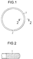
- a top ring 1 as a piston ring for an internal combustion engine is formed from a TiAl-based intermetallic compound.
- a process which is comprised of the steps of: (a) preparing a blank having a purity of 99.9% or more and melting the blank in a plasma skull melting furnace to prepare a molten metal having a TiAl-based intermetallic compound composition, (b) subjecting the molten metal to a casting process to produce an ingot having a diameter of 100 mm and a height of 50 mm, (c) subjecting the ingot to a homogenization at 1,000°C for 72 hours in vacuum, (d) subjecting the ingot to a boring to conform to the shape of a top ring in a free state, (e) subjecting a resulting ingot to a cutting-off to produce a ring blank having a predetermined thickness, (f) subjecting an outer peripheral surface of the ring blank to a lathe-turning, (g) subjecting the resulting ring blank to a cutting to define a slit corresponding to a clearance 2, (h) subjecting an inner peripheral surface of
- top rings 1 were produced with different compositions and different volume fractions Vf of LI0 type TiAl (which will be referred to as a ⁇ -phase herein).
- a top ring 1 formed from JIS SUS42OJ2 and a top ring 1 formed from a Ti-6Al-4V (90% by weight Ti; 6% by weight Al and 4% by weight V) were also produced.
- These top rings 1 were examined for whether or not the quality of machinability was good, whether or not the top ring was fractured when being mounted to a piston and whether or not there was an attenuation of tension of the top ring after a high-temperature maintaining test (according to JIS B8032).
- a specific Young's modulus and a weight ratio of the top ring of the present invention to the top ring of the SUS42OJ2 were determined, thereby providing results given in Table 1.
- ⁇ is a specific gravity (g/cm3).
- the volume fraction Vf of the ⁇ -phase was calculated by analyzing a back scattering electron composition image to determine an area rate of the ⁇ -phase. and numerically calculating the area rate.
- the quality of the machinability is represented by "O" when the lathe-turning, cutting and the like could be performed without hindrance in the producing course, and by " ⁇ " when any contrivance was required for a jig and a working way in the lathe-turning or the like.
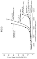
- An engine simple firing test was carried out using the examples (4), (9) to (11) and the comparative examples (3) and (12) to determine the relationship between the number of revolutions of the engine (rpm) and the amount of gas blown-by, thereby providing the results shown in Fig. 3.
- the internal combustion engine used was a serial 4-cylinder gasoline engine having a bore diameter of 72 mm, a stroke of 76 mm and an engine displacement of 1236 cc.
- engine simple firing test means a test for estimating the characteristic of the engine by burning the gasoline to revolve the engine in the same manner as in the actual driving operation.
- the limit of the number of revolutions for the comparative example (12) is as low as about 5,000 rpm. This is because a fluttering phenomenon is generated at a number of revolutions of the engine (rpm) equal to or more than about 5,000 rpm in the comparative example (12). A tendency substantially similar to that with the comparative example (12) is shown even with the comparative example (3), but an increase in the amount of gas blown-by in this case is due to an attenuation of tension.
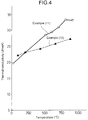
- Fig. 4 shows the relationship between the temperature and the thermal conductivity for the example (11) of the present invention and the comparative example (12) It can he seen from Fig. 4 that the thermal conductivity of the example (11) is higher than that of the comparative example (12) at an environment temperature around the top ring in a range of 250 to 350°C during operation of the engine. Thus, it is possible to improve the heat radiation of the piston to the cylinder wall.
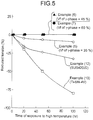
- Fig. 5 shows the relationship between the time of exposure to a high temperature and the attenuation of tension for the examples (5), (6), (7), (12) and (13).
- the conditions for the high-temperature maintaining test are the same as those described above, except that the time of exposure to the high temperature is varied.
- Fig. 6 illustrates the relationship between the thickness t of the top land 4 in the piston 3 and the variation in amount of hydrocarbons discharged.
- the conditions for operation of the engine were that the number of revolutions was 1,500 rpm and a partial opening operation (at a water temperature of 25°C).
- reference character 5 is a cylinder bore; reference character 6 is a ring groove; and reference character Tv is a top land volume.
- the top ring 1 By using the examples (6) to (11) of the top ring 1 according to the present invention, it is possible to decrease the thickness t of the top land 4 down to a range of 2 mm ⁇ t ⁇ 4 mm to reduce the amount of hydrocarbons discharged.
- a molten metal having a TiAl-based intermetallic compound composition represented by Ti 49.6 AI45V2Nb2B 1.4 (each of the numerical values is atomic %) was prepared by a high-frequency induction skull melting using a water-cooled Cu crucible within a vacuum chamber, and subjected to a centrifugal casting process to produce a cylindrical ingot including a tapered hole and having an outside diameter of 90 mm, an inside diameter of 70 mm at one end, an inside diameter of 78 mm at the other end, and a length of 150 mm.
- the ingot was subjected sequentially to a hot isostatic pressing process (HIP process) under conditions of 1300°C, 3 hours and 2,000 atmosphere, to a solution treatment under conditions of 1,200°C and 3 hours and to an aging treatment at 900°C for 8 hours.
- HIP process hot isostatic pressing process
- each of the test pieces Tp1 was subjected to a thermal treatment in a vacuum for the purpose of removing the residual strain.
- the thermal treatment temperature T was set in a range of 300°C ⁇ T ⁇ 1,000°C, and the thermal treatment time was set at 8 hours.
- Each of the test pieces was subjected to a bombard treatment for 10 minutes and then, the flat surface 7 was subjected to an ion-plating treatment as a physical vapor deposition to form a hard film F of titanium nitride (TiN) having a thickness of 10 ⁇ m.
- the ion-plating conditions were as follows: the atmospheric gas was nitrogen gas; the evaporation source was Ti; the arc current was 150 A; the bias voltage was 120 V; and the treating time was 60 minutes.
- each test piece Tp1 after the ion-plating was measured in the following manner: as shown in Fig. 9, the test piece Tp1 after the ion-plating was fixed with the film side turned upwardly (or downwardly) and with one end face 8 abutting against a vertical surface 9.
- the distance between a reference horizontal line L1 bisecting the fixed end of the test piece Tp1 in a widthwise direction and a horizontal line L2 bisecting the free end of the test piece Tp1 in the thickness-wise direction is defined as a strain S.
- Table 2 shows the relationship between the thermal treatment temperature T and the strain S after ion-plating for the examples (1) to (9) of the test pieces Tp1.
- the example (1) was not subjected to the thermal treatment for removing the residual strain after the machining.
- Table 2 Example No. of test piece Tp1 Thermal treatment temperature (°C) Strain S after ion-plating (mm) (1) - 6.3 (2) 300 4.2 (3) 400 3.9 (4) 500 0.1 (5) 600 0.05 (6) 700 0.1 (7) 800 0.2 (8) 900 0.2 (9) 1,000 3.6
- the thermal treatment temperature T was set in a range of 500°C ⁇ T ⁇ 900°C, the strain S after ion-plating was reduced to a small value less than 0.2 mm as in the examples (4) to (8). Especially, when the thermal treatment temperature T was set at 600°C, the strain S was minimized.
- test pieces Tp2 shown in Fig. 10 were subjected to a machining after the aging treatment (at 900°C for 8 hours) to fabricate a plurality of smaller test pieces Tp2 shown in Fig. 10 in order to examine the relationship between the strain after the ion-plating and the sliding characteristic.
- Each of the test pieces Tp2 has a slant 12 formed at one side edge of one flat surface 10, so that the area of the one flat surface 10 is smaller than that of the other flat surface 11.
- the one flat surface 10 was subjected to a grinding finish to adjust the 10-point average roughness R z of the flat surface to a value of 0.8 ⁇ m.
- the length b1 was 10 mm
- the width b2 was 10 mm.
- the width b3 was 11.5 mm
- the length b4 was 10 mm.
- the angle ⁇ of the slant 12 was 45° and the thickness b5 thereof was 5 mm.
- Each of the test pieces Tp2 was subjected to a thermal treatment in a vacuum for the purpose of removing the residual strain.
- the thermal treatment temperature was set in a range of 300°C ⁇ T ⁇ 1,000°C, and the thermal treatment time was set at 8 hours.
- Each of the test pieces was subjected to a bombard treatment for 10 minutes and then, the flat surface 10 was subjected to an ion-plating to form a thin film F of titanium nitride (TiN) having a thickness of 10 ⁇ m.
- the ion-plating conditions are the same as those described above, that is: the atmospheric gas was nitrogen gas; the evaporation source was Ti; the arc current was 150 A; the bias voltage was 120 V; and the treating time was 60 minutes.
- test pieces Tp2 Using the test pieces Tp2, a sliding test was carried out under lubrication in a chip-on-disk manner to examine the relationship between the thermal treatment temperature T and the seizure-generating surface pressure for the test pieces Tp2, thereby providing the results given in Table 3.
- the sliding test was carried out under conditions of a rotational speed of the disk of 5 m/sec, the amount of oil supplied of 2 cc/min and the temperature of the oil of 80°C by disposing each of the test pieces Tp2 in such a manner that the slant 12 thereof was opposed to the rotating direction of the disk of a cast iron, and urging the thin film F of titanium nitride against the disk.
- the reason why the slant 12 is disposed as described above is for the purpose of facilitating the introduction of oil between the thin film F and the disk.
- the disk includes Si, Mn, V and P.
- Table 3 the example 10 was not subjected to the thermal treatment for removing the residual strain. Table 3 Example No.
- the thermal treatment temperature T is set at a value in a range of 500° ⁇ T ⁇ 900°C
- the strain S after the ion-plating is reduced in the examples (13) to (17) of test pieces Tp2, as in the examples (4) to (8) of Tp1 test pieces in Table 2. Therefore, the entire surface of the thin film F is put into uniform sliding frictional contact with the disk, resulting in a considerably increased seizure generating surface pressure.
- the thermal treatment temperature T was set at 600°C, the seizure generating surface pressure was maximized, because the strain was minimized as described above.
- the surface pressure is locally high because of the large strain S, resulting in an extremely reduced seizure generating surface pressure.
- an example (19) of a test piece having a thin film of chromium nitride (Cr-N) formed thereon by an ion-plating treatment and an example (20) of a test piece having a thin film of titanium-aluminum nitride (TiAlN) likewise formed thereon by an ion-plating treatment were fabricated.
- the materials for both the test pieces (19) and (20) were the same as for the test pieces Tp1 and Tp2.
- chromium (Cr) was used as an evaporation source
- titanium aluminum nitride Ti50Al50 (each of the numerical values is atomic %) was used as an evaporation source.
- the strain S may be changed in some cases, and the seizure generating surface pressure is varied depending upon the material for the thin film.
- the piston ring 13 was subjected to a thermal treatment under conditions of a thermal treatment temperature T of 600°C for 8 hours for the purpose of removing the residual strain.
- the piston ring 13 was subjected to a bombard treatment for 10 minutes and then to an ion-plating treatment to form a thin film F of titanium nitride thereon.
- the thickness of the thin film F was of 10 ⁇ m at the outer peripheral surface of the piston ring 13, and 3 ⁇ m at the opposite opposed ends of the piston ring 13 which form the clearance C, the lower and upper surfaces of the piston ring 13 and at the inner peripheral surface of the piston ring 13.
- the ion-plating conditions were the same as those described above, that is: the atmospheric gas was nitrogen gas; the evaporation source was Ti; the arc current was 150 A; the bias voltage was 120 V; and the treating time was 60 minutes.
- the piston ring 13 produced in this manner was incorporated as a top ring into a 4-cylinder gasoline engine having a displacement of 1,600 cc.
- a cylinder sleeve was formed from a cast iron (Fe-C-Si-Mn-V-P) which is the same material as for the disk in the sliding test described above, and the piston was formed from an aluminum alloy (JIS AC8C).
- the gasoline engine was operated to perform a durability test for 400 hours. The results showed that an abnormal wear was not observed in the piston ring 13, the cylinder sleeve or the piston, and the attenuation of tension in the piston ring 13 was zero.
Landscapes
- Chemical & Material Sciences (AREA)
- Engineering & Computer Science (AREA)
- Mechanical Engineering (AREA)
- Materials Engineering (AREA)
- Metallurgy (AREA)
- Organic Chemistry (AREA)
- Chemical Kinetics & Catalysis (AREA)
- General Engineering & Computer Science (AREA)
- Pistons, Piston Rings, And Cylinders (AREA)
Applications Claiming Priority (4)
| Application Number | Priority Date | Filing Date | Title |
|---|---|---|---|
| JP23144993A JPH0783330A (ja) | 1993-09-17 | 1993-09-17 | 金属間化合物製ピストンリング |
| JP231449/93 | 1993-09-17 | ||
| JP3508294A JPH07243020A (ja) | 1994-03-04 | 1994-03-04 | TiAl系金属間化合物製構造部材の表面処理方法 |
| JP35082/94 | 1994-03-04 |
Publications (3)
| Publication Number | Publication Date |
|---|---|
| EP0645463A2 true EP0645463A2 (de) | 1995-03-29 |
| EP0645463A3 EP0645463A3 (de) | 1995-05-17 |
| EP0645463B1 EP0645463B1 (de) | 1997-12-29 |
Family
ID=26373998
Family Applications (1)
| Application Number | Title | Priority Date | Filing Date |
|---|---|---|---|
| EP19940114746 Expired - Lifetime EP0645463B1 (de) | 1993-09-17 | 1994-09-19 | Kolbenring aus TiAl basierender intermetallischer Verbindung und Verfahren zur Oberflächenbehandlung |
Country Status (2)
| Country | Link |
|---|---|
| EP (1) | EP0645463B1 (de) |
| DE (1) | DE69407525T2 (de) |
Cited By (5)
| Publication number | Priority date | Publication date | Assignee | Title |
|---|---|---|---|---|
| WO2002088407A1 (en) * | 2001-03-27 | 2002-11-07 | Koncentra Verkstads Ab | Nickel-aluminide based wear resistant material for piston rings |
| US6485026B1 (en) | 2000-10-04 | 2002-11-26 | Dana Corporation | Non-stainless steel nitrided piston ring, and method of making the same |
| WO2005085743A1 (de) * | 2004-03-08 | 2005-09-15 | Moerth Marlene | Verfahren zur pvd-innenbeschichtung von metallischen werkstücken mit tiefen bohrungen und läufen von feuerwaffen |
| US9447490B2 (en) | 2007-07-28 | 2016-09-20 | Federal-Mogul Burscheid Gmbh | Piston ring |
| US9995393B2 (en) | 2013-08-01 | 2018-06-12 | Mahle Metal Leve S/A | Piston ring and method for manufacturing same |
Families Citing this family (1)
| Publication number | Priority date | Publication date | Assignee | Title |
|---|---|---|---|---|
| DE10025132A1 (de) * | 2000-05-20 | 2001-11-22 | Volkswagen Ag | Kolben für eine Verbrennungskraftmaschine und Verfahren zur Herstellung eines Kolbens |
Family Cites Families (3)
| Publication number | Priority date | Publication date | Assignee | Title |
|---|---|---|---|---|
| JPS6258050A (ja) * | 1985-09-05 | 1987-03-13 | Toyota Motor Corp | ピストンリング |
| JPH042702A (ja) * | 1990-04-20 | 1992-01-07 | Isuzu Motors Ltd | ピストンの製造方法 |
| JPH05126255A (ja) * | 1991-11-06 | 1993-05-21 | Atsugi Unisia Corp | 内燃機関用ピストンピン |
-
1994
- 1994-09-19 EP EP19940114746 patent/EP0645463B1/de not_active Expired - Lifetime
- 1994-09-19 DE DE1994607525 patent/DE69407525T2/de not_active Expired - Fee Related
Cited By (10)
| Publication number | Priority date | Publication date | Assignee | Title |
|---|---|---|---|---|
| US6485026B1 (en) | 2000-10-04 | 2002-11-26 | Dana Corporation | Non-stainless steel nitrided piston ring, and method of making the same |
| WO2002088407A1 (en) * | 2001-03-27 | 2002-11-07 | Koncentra Verkstads Ab | Nickel-aluminide based wear resistant material for piston rings |
| WO2002088406A1 (en) * | 2001-03-27 | 2002-11-07 | Koncentra Verkstads Ab | Intermetallic wear-resistant material for piston rings |
| US6838196B2 (en) | 2001-03-27 | 2005-01-04 | Koncentra Holding Ab | Nickel-aluminide based wear resistant material for piston rings |
| EP1524459A3 (de) * | 2001-03-27 | 2005-04-27 | Koncentra Holding AB | Einen verschleissfesten Werkstoff enthaltender Kolbenring |
| US7052018B2 (en) | 2001-03-27 | 2006-05-30 | Koncentra Marine & Power Ab | Piston ring having wear resistant composition |
| KR100854666B1 (ko) * | 2001-03-27 | 2008-08-27 | 콘센트라 마린 앤드 파워 아베 | 피스톤 링용의 내마모성 니켈-알루미나이드계 재료 |
| WO2005085743A1 (de) * | 2004-03-08 | 2005-09-15 | Moerth Marlene | Verfahren zur pvd-innenbeschichtung von metallischen werkstücken mit tiefen bohrungen und läufen von feuerwaffen |
| US9447490B2 (en) | 2007-07-28 | 2016-09-20 | Federal-Mogul Burscheid Gmbh | Piston ring |
| US9995393B2 (en) | 2013-08-01 | 2018-06-12 | Mahle Metal Leve S/A | Piston ring and method for manufacturing same |
Also Published As
| Publication number | Publication date |
|---|---|
| EP0645463B1 (de) | 1997-12-29 |
| DE69407525D1 (de) | 1998-02-05 |
| DE69407525T2 (de) | 1998-04-16 |
| EP0645463A3 (de) | 1995-05-17 |
Similar Documents
| Publication | Publication Date | Title |
|---|---|---|
| EP1304393B1 (de) | Kolbenring mit ausgezeichneter beständigkeit gegen reibung, rissbildung und ermüdung und herstellungsverfahren dafür und kombination von kolbenriing und zylinderblock | |
| US5316321A (en) | Nonferrous piston ring with hard surface treatment layer | |
| EP1963721B1 (de) | Kolbenring für verbrennungsmotoren | |
| EP1359351B1 (de) | Kolbenring und verfahren zur herstellung desselben | |
| EP0849370B1 (de) | Hochfeste Superlegierungsgegenstände auf Nickel-Basis und mit einer bearbeiteten Fläche | |
| JP5564099B2 (ja) | シリンダとピストンリングの組合せ | |
| EP2725266B1 (de) | Kolbenring | |
| EP0707092B1 (de) | Gleitstück und verfahren zu dessen herstellung | |
| EP0645463A2 (de) | Kolbenring aus TiAl basierender intermetallischer Verbindung und Verfahren zur Oberflächenbehandlung | |
| JP2739722B2 (ja) | ピストンリング | |
| JP2005060810A (ja) | 被覆材及びその製造方法 | |
| JPH08312779A (ja) | 摺動材料およびピストンリング | |
| US4986234A (en) | Polymetallic piston-cylinder configuration for internal combustion engines | |
| JP2968907B2 (ja) | 耐摩耗性被膜 | |
| EP0139732B1 (de) | Harte schicht hergestellt durch einbringen von stickstoff in molybdän und wolfram und verfahren zur herstellung dieser schicht | |
| JP4374153B2 (ja) | ピストンリング | |
| GB2175920A (en) | Laminar material for plain bearings having an antifriction layer of an aluminium-based alloy | |
| JP4374154B2 (ja) | ピストンリング | |
| US6315840B1 (en) | Sliding member | |
| EP1448918B1 (de) | Kolben für verbrennungsmotor | |
| JP4374160B2 (ja) | ピストンリング | |
| JPH07243020A (ja) | TiAl系金属間化合物製構造部材の表面処理方法 | |
| EP0533128B1 (de) | Kolbenring aus Titan-Legierung und Verfahren zur Herstellung | |
| JP3239610B2 (ja) | ピストン/ピストンリングアッセンブリ | |
| JP2500147B2 (ja) | ピストンリング |
Legal Events
| Date | Code | Title | Description |
|---|---|---|---|
| PUAI | Public reference made under article 153(3) epc to a published international application that has entered the european phase |
Free format text: ORIGINAL CODE: 0009012 |
|
| PUAL | Search report despatched |
Free format text: ORIGINAL CODE: 0009013 |
|
| AK | Designated contracting states |
Kind code of ref document: A2 Designated state(s): DE FR GB |
|
| AK | Designated contracting states |
Kind code of ref document: A3 Designated state(s): DE FR GB |
|
| 17P | Request for examination filed |
Effective date: 19950531 |
|
| 17Q | First examination report despatched |
Effective date: 19950713 |
|
| GRAG | Despatch of communication of intention to grant |
Free format text: ORIGINAL CODE: EPIDOS AGRA |
|
| GRAH | Despatch of communication of intention to grant a patent |
Free format text: ORIGINAL CODE: EPIDOS IGRA |
|
| GRAH | Despatch of communication of intention to grant a patent |
Free format text: ORIGINAL CODE: EPIDOS IGRA |
|
| GRAA | (expected) grant |
Free format text: ORIGINAL CODE: 0009210 |
|
| AK | Designated contracting states |
Kind code of ref document: B1 Designated state(s): DE FR GB |
|
| REF | Corresponds to: |
Ref document number: 69407525 Country of ref document: DE Date of ref document: 19980205 |
|
| ET | Fr: translation filed | ||
| PGFP | Annual fee paid to national office [announced via postgrant information from national office to epo] |
Ref country code: FR Payment date: 19980922 Year of fee payment: 5 |
|
| PGFP | Annual fee paid to national office [announced via postgrant information from national office to epo] |
Ref country code: DE Payment date: 19980930 Year of fee payment: 5 |
|
| PGFP | Annual fee paid to national office [announced via postgrant information from national office to epo] |
Ref country code: GB Payment date: 19981002 Year of fee payment: 5 |
|
| PLBE | No opposition filed within time limit |
Free format text: ORIGINAL CODE: 0009261 |
|
| STAA | Information on the status of an ep patent application or granted ep patent |
Free format text: STATUS: NO OPPOSITION FILED WITHIN TIME LIMIT |
|
| 26N | No opposition filed | ||
| PG25 | Lapsed in a contracting state [announced via postgrant information from national office to epo] |
Ref country code: GB Free format text: LAPSE BECAUSE OF NON-PAYMENT OF DUE FEES Effective date: 19990919 |
|
| GBPC | Gb: european patent ceased through non-payment of renewal fee |
Effective date: 19990919 |
|
| PG25 | Lapsed in a contracting state [announced via postgrant information from national office to epo] |
Ref country code: FR Free format text: LAPSE BECAUSE OF NON-PAYMENT OF DUE FEES Effective date: 20000531 |
|
| PG25 | Lapsed in a contracting state [announced via postgrant information from national office to epo] |
Ref country code: DE Free format text: LAPSE BECAUSE OF NON-PAYMENT OF DUE FEES Effective date: 20000701 |
|
| REG | Reference to a national code |
Ref country code: FR Ref legal event code: ST |