EP0645577A1 - Support - Google Patents
Support Download PDFInfo
- Publication number
- EP0645577A1 EP0645577A1 EP94810552A EP94810552A EP0645577A1 EP 0645577 A1 EP0645577 A1 EP 0645577A1 EP 94810552 A EP94810552 A EP 94810552A EP 94810552 A EP94810552 A EP 94810552A EP 0645577 A1 EP0645577 A1 EP 0645577A1
- Authority
- EP
- European Patent Office
- Prior art keywords
- column
- support
- support according
- passage
- locking
- Prior art date
- Legal status (The legal status is an assumption and is not a legal conclusion. Google has not performed a legal analysis and makes no representation as to the accuracy of the status listed.)
- Ceased
Links
- 241000209035 Ilex Species 0.000 description 3
- 238000004519 manufacturing process Methods 0.000 description 3
- 239000011324 bead Substances 0.000 description 2
- 238000006073 displacement reaction Methods 0.000 description 2
- 230000000694 effects Effects 0.000 description 1
- 238000001746 injection moulding Methods 0.000 description 1
- 238000009434 installation Methods 0.000 description 1
- 125000006850 spacer group Chemical group 0.000 description 1
Images

Classifications
-
- F—MECHANICAL ENGINEERING; LIGHTING; HEATING; WEAPONS; BLASTING
- F16—ENGINEERING ELEMENTS AND UNITS; GENERAL MEASURES FOR PRODUCING AND MAINTAINING EFFECTIVE FUNCTIONING OF MACHINES OR INSTALLATIONS; THERMAL INSULATION IN GENERAL
- F16B—DEVICES FOR FASTENING OR SECURING CONSTRUCTIONAL ELEMENTS OR MACHINE PARTS TOGETHER, e.g. NAILS, BOLTS, CIRCLIPS, CLAMPS, CLIPS OR WEDGES; JOINTS OR JOINTING
- F16B12/00—Jointing of furniture or the like, e.g. hidden from exterior
- F16B12/10—Jointing of furniture or the like, e.g. hidden from exterior using pegs, bolts, tenons, clamps, clips, or the like
- F16B12/12—Jointing of furniture or the like, e.g. hidden from exterior using pegs, bolts, tenons, clamps, clips, or the like for non-metal furniture parts, e.g. made of wood, of plastics
- F16B12/20—Jointing of furniture or the like, e.g. hidden from exterior using pegs, bolts, tenons, clamps, clips, or the like for non-metal furniture parts, e.g. made of wood, of plastics using clamps, clips, wedges, sliding bolts, or the like
-
- A—HUMAN NECESSITIES
- A47—FURNITURE; DOMESTIC ARTICLES OR APPLIANCES; COFFEE MILLS; SPICE MILLS; SUCTION CLEANERS IN GENERAL
- A47B—TABLES; DESKS; OFFICE FURNITURE; CABINETS; DRAWERS; GENERAL DETAILS OF FURNITURE
- A47B57/00—Cabinets, racks or shelf units, characterised by features for adjusting shelves or partitions
- A47B57/30—Cabinets, racks or shelf units, characterised by features for adjusting shelves or partitions with means for adjusting the height of detachable shelf supports
- A47B57/54—Cabinets, racks or shelf units, characterised by features for adjusting shelves or partitions with means for adjusting the height of detachable shelf supports consisting of clamping means, e.g. with sliding bolts or sliding wedges
- A47B57/545—Cabinets, racks or shelf units, characterised by features for adjusting shelves or partitions with means for adjusting the height of detachable shelf supports consisting of clamping means, e.g. with sliding bolts or sliding wedges clamped in discrete positions, e.g. on tubes with grooves or holes
-
- F—MECHANICAL ENGINEERING; LIGHTING; HEATING; WEAPONS; BLASTING
- F16—ENGINEERING ELEMENTS AND UNITS; GENERAL MEASURES FOR PRODUCING AND MAINTAINING EFFECTIVE FUNCTIONING OF MACHINES OR INSTALLATIONS; THERMAL INSULATION IN GENERAL
- F16B—DEVICES FOR FASTENING OR SECURING CONSTRUCTIONAL ELEMENTS OR MACHINE PARTS TOGETHER, e.g. NAILS, BOLTS, CIRCLIPS, CLAMPS, CLIPS OR WEDGES; JOINTS OR JOINTING
- F16B7/00—Connections of rods or tubes, e.g. of non-circular section, mutually, including resilient connections
- F16B7/10—Telescoping systems
- F16B7/105—Telescoping systems locking in discrete positions, e.g. in extreme extended position
-
- F—MECHANICAL ENGINEERING; LIGHTING; HEATING; WEAPONS; BLASTING
- F16—ENGINEERING ELEMENTS AND UNITS; GENERAL MEASURES FOR PRODUCING AND MAINTAINING EFFECTIVE FUNCTIONING OF MACHINES OR INSTALLATIONS; THERMAL INSULATION IN GENERAL
- F16M—FRAMES, CASINGS OR BEDS OF ENGINES, MACHINES OR APPARATUS, NOT SPECIFIC TO ENGINES, MACHINES OR APPARATUS PROVIDED FOR ELSEWHERE; STANDS; SUPPORTS
- F16M11/00—Stands or trestles as supports for apparatus or articles placed thereon ; Stands for scientific apparatus such as gravitational force meters
- F16M11/02—Heads
- F16M11/04—Means for attachment of apparatus; Means allowing adjustment of the apparatus relatively to the stand
- F16M11/043—Allowing translations
- F16M11/046—Allowing translations adapted to upward-downward translation movement
-
- F—MECHANICAL ENGINEERING; LIGHTING; HEATING; WEAPONS; BLASTING
- F16—ENGINEERING ELEMENTS AND UNITS; GENERAL MEASURES FOR PRODUCING AND MAINTAINING EFFECTIVE FUNCTIONING OF MACHINES OR INSTALLATIONS; THERMAL INSULATION IN GENERAL
- F16M—FRAMES, CASINGS OR BEDS OF ENGINES, MACHINES OR APPARATUS, NOT SPECIFIC TO ENGINES, MACHINES OR APPARATUS PROVIDED FOR ELSEWHERE; STANDS; SUPPORTS
- F16M11/00—Stands or trestles as supports for apparatus or articles placed thereon ; Stands for scientific apparatus such as gravitational force meters
- F16M11/02—Heads
- F16M11/16—Details concerning attachment of head-supporting legs, with or without actuation of locking members thereof
-
- A—HUMAN NECESSITIES
- A47—FURNITURE; DOMESTIC ARTICLES OR APPLIANCES; COFFEE MILLS; SPICE MILLS; SUCTION CLEANERS IN GENERAL
- A47B—TABLES; DESKS; OFFICE FURNITURE; CABINETS; DRAWERS; GENERAL DETAILS OF FURNITURE
- A47B2220/00—General furniture construction, e.g. fittings
- A47B2220/0061—Accessories
- A47B2220/0066—Glide-shoes for furniture and not for feet
-
- F—MECHANICAL ENGINEERING; LIGHTING; HEATING; WEAPONS; BLASTING
- F16—ENGINEERING ELEMENTS AND UNITS; GENERAL MEASURES FOR PRODUCING AND MAINTAINING EFFECTIVE FUNCTIONING OF MACHINES OR INSTALLATIONS; THERMAL INSULATION IN GENERAL
- F16M—FRAMES, CASINGS OR BEDS OF ENGINES, MACHINES OR APPARATUS, NOT SPECIFIC TO ENGINES, MACHINES OR APPARATUS PROVIDED FOR ELSEWHERE; STANDS; SUPPORTS
- F16M2200/00—Details of stands or supports
- F16M2200/02—Locking means
- F16M2200/025—Locking means for translational movement
- F16M2200/028—Locking means for translational movement by positive interaction, e.g. male-female connections
Definitions
- the present invention relates to a support, in particular for arranging and positioning shelves, screens, shelves, folders and the like, with a column, which has a plurality of spaced-apart recesses, an adjusting device having a passage for the column, which has a locking element has, which can be brought into engagement with one of the recesses to lock the column in the desired position.
- US-A-2 128 409 shows a telescope tripod with a column supporting the telescope, which has a plurality of spaced apart grooves.
- An adjusting device has a screw as a locking element, which can be brought into engagement with one of the recesses in order to lock the column in the desired position.
- the carriage shown in US-A-4,763,799 has four fixed columns, to which two floors are fastened in an adjustable manner.
- the adjustment device shown there therefore does not serve as support for a column, but rather the column serves as support for the adjustment device, which is designed as part of the height-adjustable floor.
- the pillars of the car have a number of grooves which are spaced apart and lead through passages which are arranged at the four corners of a floor. These passages have a downwardly widening conical section into which two shell halves fit, the inner contour of which corresponds to the column, an inwardly directed bead being able to engage in a groove in the column.
- the floor In order to adjust the height of a floor, the floor must be raised. The shell halves can then be removed and reinserted elsewhere on the column so that the beads engage in a groove, after which the bottom can be lowered again.
- the support should also be able to be manufactured efficiently.
- the passage for the column also has space for inserting the locking element from above, that the locking element on the column is displaceable and lockable, and a detent cam and a stop has, in order to adjust the height of the column, the locking element can be moved outside the passage into the desired locking position in which the locking cam engages in one of the recesses, whereupon the column can be moved down until this movement is limited by the stop.
- the support is given a compact form by dispensing with a conventional locking screw.
- the manufacturing costs can be kept low.
- the locking mechanism according to the invention has the advantage that no tools are required to adjust the height of the support, and no more loosening and tightening of screws is necessary. Handling is also simplified in that, unlike the object of US Pat. No. 4,763,799, the locking element can be manipulated from above.
- the column is advantageously a rod or tube.
- the locking element is expediently a sleeve which has at least one, advantageously a plurality of fingers with a cam.
- the finger or fingers are advantageously designed so that the sleeve can be easily moved from one position to the other, where the cam or cams snap into the recesses and can thus fix the sleeve in this position. This simplifies handling because the sleeve no longer has to be held by hand when the column is lowered.
- the recesses are preferably formed by a plurality of transverse grooves. This means that the column can also be rotated. This is particularly important when arranging screens in an office workplace. The distance between two adjacent grooves corresponds to the minimum displacement distance of the column.
- the fingers have wedge-shaped ends in cross section.
- the sleeve can then be inserted particularly easily into the guide.
- the guide advantageously has a cone which tapers sharply towards the end at the lower end on. This cone can accommodate the wedge-shaped ends of the fingers, whereby the locking effect can be improved even more, without the determination being difficult to solve.
- the guide expediently has a countersunk entry opening. Through this inlet opening, the sleeve can also be easily inserted when the column is at an angle.
- the adjustment device advantageously consists of a lower part and an upper part.
- the upper and lower part can be inexpensively manufactured, for example, from plastic using the injection molding process.
- the lower part advantageously has a sliding shoe for moving and attaching the support to a rail, in particular to a rail consisting of two guide rails arranged at a distance from one another.
- the support can be moved horizontally.
- the cross section of the slide shoe advantageously has the shape of a flattened O, from which about a quarter is cut away to form an opening for hanging on the rail, so that the lower part simply has to be hung on the rail during assembly.
- a threaded bushing is expediently provided on the lower part in order to fix the upper part on the lower part by means of a locking screw and at the same time to lock the adjusting device on the railing.
- the guide can be slightly deformed by tightening the locking screw, so that it presses against the railing and the support is thereby fixed on the railing.
- the upper part advantageously has a guide socket for the locking screw, which is dimensioned and arranged on the upper part in such a way that when the support is arranged it comes to rest on the railing between the two guide rails and bears against this and against the guide part. As a result, a force acting laterally on the column is transmitted through the connecting piece to the lower guide rail.
- Two or more supports can advantageously be used for holding an elongated object, for example for forming shelves or for arranging screens.
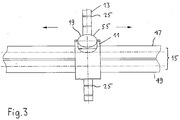
- Figures 1 to 3 show a support with an adjustable, in particular height-adjustable column 13 and an adjusting device 11.
- the support is horizontally displaceable, for example, on a rail 15 consisting of two guide rails 47, 49.
- the adjusting device 11 can be locked on the railing 15 by a locking screw 19 (FIG. 3).
- the column 13 is guided in a passage 21 of the adjusting device 11.
- the position of the column 13 can be determined by a sleeve 23.
- the column 13 has a multiplicity of grooves 25 arranged at intervals from one another, into which the sleeve 23 fitting into the passage 21 can engage with cams 27.
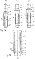
- the details of the sleeve 23 are shown in Figure 4.
- the sleeve 23 has a stop 29 and a plurality of resilient fingers 31.
- the fingers 31 have the cams 27 already mentioned on the inner surface, which have a shape corresponding to the grooves 25 (FIG. 4b).
- the fingers 31 are wedge-shaped at the lower end 33.
- the inlet opening 35 (FIG. 2a) of the passage 21 is countersunk, so that the lower end 33 of the fingers 31 is gripped by the inlet opening 35 even when the column 13 is not vertically aligned.
- the passage 21 can be slightly conical.
- the lower end of the passage 21 has a cone 37 (FIG. 2b) which tapers towards the end, the cone angle of which corresponds to the wedge-shaped ends 33 of the fingers 31.
- the column 13 can consist of a tube 14 or a rod.
- the adjusting device 11 shown in FIGS. 1 and 2 consisting of a lower part 41 and an upper part 43, has a sliding shoe 45 which accommodates the railing 15 (FIG. 3).
- the slide shoe 45 has the shape of a flattened O's, from which about a quarter is cut away to form an opening for hanging on the railing 15.
- the lower part 41 of the adjusting device 11 can first be hooked onto the upper guide rail 47 and then pivoted so that the slide shoe 45 rests on the railing 15 on three sides.
- the lower part 41 bears against the lower guide rail 49 of the rail 15 when the column 13 is loaded, so that the column 13 projects vertically upward.
- the adjusting device 11 is clamped on the railing 15 by means of the locking screw 19, which interacts with the threaded bushing 51 arranged on the sliding block 45.
- the threaded bushing 51 can be cast, for example, on the lower part 41 of the sliding block 45.
- the upper part 43 is also held on the lower part 41 by the locking screw 19.
- the upper part 43 consists of a semicircular housing with a guide socket 53 for the locking screw 19.
- the socket 53 has a diameter corresponding approximately to the distance between the two guide rails 47, 49.
- the guide part 46 abuts the socket 53, so that a force acting on the column 13 in the direction of the arrow 48 (FIG. 2a) is transmitted through the socket 53 to the lower guide rail 49. This prevents the column 13 from tipping over the railing 15.
- the nozzle 53 also has the function of a spacer.
- the screw 19 can only be tightened until the connecting piece 53 and the lower part 41 abut one another. This reduces the risk that the slide shoe 45 will be damaged by tightening the screw 19 too much.
- a strong screwing is also not necessary, by the way, since the tightening of the locking screw 19 only has to prevent the support 11 from slipping sideways.
- the head of the screw is designed as a rotary knob 55.
- the adjustment of the column 13 can be accomplished simply and very quickly: first the column 13 with the sleeve is lifted out of the passage 21, and the sleeve 23 is shifted to the desired location until the cams 27 in one of the grooves 25 engage. Then the column 13 is lowered again. When lowering the column 13 is stored practically without play.
- the fingers 31 engage with the cams 27 in the lowest of the grooves 25 in the position 1). If the sleeve 23 is moved upward, the fingers 31 are spread outwards in a resilient manner (position 2), as can be seen in particular from FIG. 4b. As soon as the cams 27 arrive at the next groove 25, they snap into this. The sleeve 23 can thus be pushed to any groove 25, whereupon the column 13 can be lowered again.
Landscapes
- Engineering & Computer Science (AREA)
- General Engineering & Computer Science (AREA)
- Mechanical Engineering (AREA)
- Legs For Furniture In General (AREA)
Applications Claiming Priority (2)
| Application Number | Priority Date | Filing Date | Title |
|---|---|---|---|
| CH289293 | 1993-09-24 | ||
| CH2892/93 | 1993-09-24 |
Publications (1)
| Publication Number | Publication Date |
|---|---|
| EP0645577A1 true EP0645577A1 (fr) | 1995-03-29 |
Family
ID=4243949
Family Applications (1)
| Application Number | Title | Priority Date | Filing Date |
|---|---|---|---|
| EP94810552A Ceased EP0645577A1 (fr) | 1993-09-24 | 1994-09-23 | Support |
Country Status (1)
| Country | Link |
|---|---|
| EP (1) | EP0645577A1 (fr) |
Cited By (1)
| Publication number | Priority date | Publication date | Assignee | Title |
|---|---|---|---|---|
| CN111396424A (zh) * | 2019-08-21 | 2020-07-10 | 绿城装饰工程集团有限公司 | 一种装配式中式亭框架用安装件 |
Citations (7)
| Publication number | Priority date | Publication date | Assignee | Title |
|---|---|---|---|---|
| CH125026A (de) * | 1927-02-25 | 1928-03-16 | Herm Mumprecht | Klemmvorrichtung zur Arretierung der Stützstangen von Turnbarren. |
| US2128409A (en) * | 1936-08-28 | 1938-08-30 | Emil F Hager | Scope stand |
| GB2081362A (en) * | 1980-07-11 | 1982-02-17 | Victor Company Of Japan | Fixing device having two pivotally interconnected clamps |
| DE8607337U1 (de) * | 1986-03-17 | 1986-07-24 | Kemmann & Koch, 5620 Velbert | Verstellvorrichtung für Möbelbeschläge und dgl. |
| FR2593046A1 (fr) * | 1986-01-22 | 1987-07-24 | Maurel Guy | Poste de travail ergonomique pour la pratique du dessin assiste par ordinateur. |
| US4763799A (en) * | 1987-09-17 | 1988-08-16 | Intermetro Industries Corporation | Modular utility cart including improved structures for securing intermediate and top shelves to corner posts |
| DE3920285A1 (de) * | 1989-06-21 | 1991-01-03 | Bolte Gmbh Erich | Aus bauelementen zusammengesetzter buerotisch |
-
1994
- 1994-09-23 EP EP94810552A patent/EP0645577A1/fr not_active Ceased
Patent Citations (7)
| Publication number | Priority date | Publication date | Assignee | Title |
|---|---|---|---|---|
| CH125026A (de) * | 1927-02-25 | 1928-03-16 | Herm Mumprecht | Klemmvorrichtung zur Arretierung der Stützstangen von Turnbarren. |
| US2128409A (en) * | 1936-08-28 | 1938-08-30 | Emil F Hager | Scope stand |
| GB2081362A (en) * | 1980-07-11 | 1982-02-17 | Victor Company Of Japan | Fixing device having two pivotally interconnected clamps |
| FR2593046A1 (fr) * | 1986-01-22 | 1987-07-24 | Maurel Guy | Poste de travail ergonomique pour la pratique du dessin assiste par ordinateur. |
| DE8607337U1 (de) * | 1986-03-17 | 1986-07-24 | Kemmann & Koch, 5620 Velbert | Verstellvorrichtung für Möbelbeschläge und dgl. |
| US4763799A (en) * | 1987-09-17 | 1988-08-16 | Intermetro Industries Corporation | Modular utility cart including improved structures for securing intermediate and top shelves to corner posts |
| DE3920285A1 (de) * | 1989-06-21 | 1991-01-03 | Bolte Gmbh Erich | Aus bauelementen zusammengesetzter buerotisch |
Cited By (1)
| Publication number | Priority date | Publication date | Assignee | Title |
|---|---|---|---|---|
| CN111396424A (zh) * | 2019-08-21 | 2020-07-10 | 绿城装饰工程集团有限公司 | 一种装配式中式亭框架用安装件 |
Similar Documents
| Publication | Publication Date | Title |
|---|---|---|
| DE29906637U1 (de) | Computertisch | |
| DE3635244A1 (de) | Stuhl, insbesondere buerostuhl, mit hoehenverstellbarer rueckenlehne | |
| DE3939257B4 (de) | Schublade | |
| DE102020134999A1 (de) | Armlehnenstruktur, die ein verstellbares Anheben und Senken ermöglicht | |
| DE4332437C2 (de) | Tisch und Tischsystem | |
| DE3151986C2 (de) | Vorrichtung zum Führen und Verstellen der Höhe einer Tischplatte | |
| EP0610707B1 (fr) | Dispositif ajustable en hauteur | |
| EP0645577A1 (fr) | Support | |
| EP0681891A1 (fr) | Table de travail et de montage | |
| AT399086B (de) | Verstellvorrichtung für schubladenblenden, insbesondere für küchenmöbelauszüge | |
| EP0040180A1 (fr) | Tréteau de montage | |
| AT400795B (de) | Schublade | |
| EP1464849A2 (fr) | Appui télescopant réglable | |
| DE19511176C2 (de) | Vorrichtung zur Verstellung der Höhe und/oder Neigung der Tischplatte eines Tisches | |
| DE3902828A1 (de) | Stativ | |
| EP0602378A1 (fr) | Dispositif de montage pour hottes d'évacuation defumées encastrées ou annexes à des éléments d'armoire suspendue | |
| DE10018379A1 (de) | Einschub | |
| DE9310664U1 (de) | Höhenverstellbarer Tisch | |
| DE102018008156A1 (de) | Vorrichtung zur Aufnahme einer Platte einer Geländeranordnung | |
| DE69401461T2 (de) | Teleskop-Richtstange mit Schnurhalteelement | |
| EP1068819A1 (fr) | Pupitre avec appui intégré pour les pieds | |
| DE4212412A1 (de) | Vorrichtung zur höhenverstellbaren Anordung von Bürogeräten oder -möbelteilen | |
| DE2747777A1 (de) | Untergestell fuer einen stuhl | |
| DE202017107693U1 (de) | Sockelhöhenversteller für Möbel | |
| DE202007003808U1 (de) | Seitengitter |
Legal Events
| Date | Code | Title | Description |
|---|---|---|---|
| PUAI | Public reference made under article 153(3) epc to a published international application that has entered the european phase |
Free format text: ORIGINAL CODE: 0009012 |
|
| AK | Designated contracting states |
Kind code of ref document: A1 Designated state(s): AT CH DE FR IT LI |
|
| 17P | Request for examination filed |
Effective date: 19950602 |
|
| GRAG | Despatch of communication of intention to grant |
Free format text: ORIGINAL CODE: EPIDOS AGRA |
|
| 17Q | First examination report despatched |
Effective date: 19960926 |
|
| STAA | Information on the status of an ep patent application or granted ep patent |
Free format text: STATUS: THE APPLICATION HAS BEEN REFUSED |
|
| 18R | Application refused |
Effective date: 19970321 |