EP0645657A1 - Vorrichtung zum Verbinden optischer Fibern - Google Patents
Vorrichtung zum Verbinden optischer Fibern Download PDFInfo
- Publication number
- EP0645657A1 EP0645657A1 EP94402110A EP94402110A EP0645657A1 EP 0645657 A1 EP0645657 A1 EP 0645657A1 EP 94402110 A EP94402110 A EP 94402110A EP 94402110 A EP94402110 A EP 94402110A EP 0645657 A1 EP0645657 A1 EP 0645657A1
- Authority
- EP
- European Patent Office
- Prior art keywords
- optical fibers
- chassis
- cassettes
- along
- cassette
- Prior art date
- Legal status (The legal status is an assumption and is not a legal conclusion. Google has not performed a legal analysis and makes no representation as to the accuracy of the status listed.)
- Granted
Links
- 230000003287 optical effect Effects 0.000 title claims 2
- 239000013307 optical fiber Substances 0.000 claims abstract description 83
- 239000000835 fiber Substances 0.000 claims abstract description 4
- 239000004744 fabric Substances 0.000 claims description 7
- 238000005452 bending Methods 0.000 claims description 4
- 230000005693 optoelectronics Effects 0.000 claims description 3
- 230000002441 reversible effect Effects 0.000 claims description 2
- 210000002105 tongue Anatomy 0.000 description 4
- 238000000465 moulding Methods 0.000 description 3
- 230000005540 biological transmission Effects 0.000 description 2
- 238000003780 insertion Methods 0.000 description 2
- 230000037431 insertion Effects 0.000 description 2
- 229920000297 Rayon Polymers 0.000 description 1
- 230000001174 ascending effect Effects 0.000 description 1
- 230000015572 biosynthetic process Effects 0.000 description 1
- 238000006243 chemical reaction Methods 0.000 description 1
- 230000000694 effects Effects 0.000 description 1
- 235000021183 entrée Nutrition 0.000 description 1
- 230000003100 immobilizing effect Effects 0.000 description 1
- 230000014759 maintenance of location Effects 0.000 description 1
- 239000000463 material Substances 0.000 description 1
- 238000012986 modification Methods 0.000 description 1
- 230000004048 modification Effects 0.000 description 1
- 239000002964 rayon Substances 0.000 description 1
- 238000007789 sealing Methods 0.000 description 1
- 238000000926 separation method Methods 0.000 description 1
Images


Classifications
-
- G—PHYSICS
- G02—OPTICS
- G02B—OPTICAL ELEMENTS, SYSTEMS OR APPARATUS
- G02B6/00—Light guides; Structural details of arrangements comprising light guides and other optical elements, e.g. couplings
- G02B6/44—Mechanical structures for providing tensile strength and external protection for fibres, e.g. optical transmission cables
- G02B6/4439—Auxiliary devices
- G02B6/444—Systems or boxes with surplus lengths
- G02B6/4453—Cassettes
- G02B6/4455—Cassettes characterised by the way of extraction or insertion of the cassette in the distribution frame, e.g. pivoting, sliding, rotating or gliding
-
- G—PHYSICS
- G02—OPTICS
- G02B—OPTICAL ELEMENTS, SYSTEMS OR APPARATUS
- G02B6/00—Light guides; Structural details of arrangements comprising light guides and other optical elements, e.g. couplings
- G02B6/44—Mechanical structures for providing tensile strength and external protection for fibres, e.g. optical transmission cables
- G02B6/4439—Auxiliary devices
- G02B6/444—Systems or boxes with surplus lengths
- G02B6/4452—Distribution frames
- G02B6/44526—Panels or rackmounts covering a whole width of the frame or rack
-
- G—PHYSICS
- G02—OPTICS
- G02B—OPTICAL ELEMENTS, SYSTEMS OR APPARATUS
- G02B6/00—Light guides; Structural details of arrangements comprising light guides and other optical elements, e.g. couplings
- G02B6/44—Mechanical structures for providing tensile strength and external protection for fibres, e.g. optical transmission cables
- G02B6/4439—Auxiliary devices
- G02B6/444—Systems or boxes with surplus lengths
- G02B6/44528—Patch-cords; Connector arrangements in the system or in the box
Definitions
- the present invention relates to a connection device for optical fibers, sometimes called a splice organizer or cable head.
- French patent application FR-2 646 928 discloses a connection device comprising a chassis of elongated parallelepiped shape, provided with a plurality of articulated cassettes each comprising means for accommodating reserve lengths of optical fibers and the splices of the optical fibers connected.
- the bringing of the optical fibers into the chassis and the departure of the optical fibers towards the outside takes place through opposite walls of the frame and the pivoting of the cassettes takes place around axes parallel to these opposite walls.
- the optical fibers enter and leave a cassette through passages formed on a wall thereof parallel to the pivot axis, which requires, in order to respect the minimum radius of curvature of the optical fibers allowing correct transmission of light , move the cassettes away from their pivot axis by mounting them at the end of articulated arms.
- the pivoting of the cassettes is thus carried out in a large volume, to the detriment of the storage capacity of optical fibers, and on the side relative to the operator in charge of the wiring, which makes the operations to be carried out in the cassettes difficult.
- a tube is provided for guiding the optical fibers from the departure of the cassettes, and the insertion of the optical fibers into this tube is a costly operation in terms of labor time.
- connection device intended in particular to facilitate the operations of wiring and splicing of optical fibers, while offering a large storage capacity for optical fibers
- this connection device being of the type comprising a chassis having two side walls joined together at the bottom by a bottom and comprising a plurality of hinged and superimposed cassettes, each provided with means for accommodating reserve lengths of optical fibers and the splices of the connected optical fibers.
- each cassette has a side inlet and a side outlet for optical fibers, located opposite each other, two drums on which are coiled the optical fibers arriving and leaving respectively by said side inlet and outlet and a box for storing splices, located between the two drums.
- the cassettes are provided at the rear with mounting tabs formed by bending at right angles to a rear edge raised from the cassette or coming from molding, each crossed by two holes for the articulated connection with an immediately superior cassette and an immediately lower cassette respectively, said lateral optical fiber inlets and outlets being formed near said mounting tabs.
- the cassettes are articulated so that the pivoting towards the rear takes place over more than 90 °.
- the cassettes located under the upper cassette are each provided with first attachment means and the cassettes located above the lower cassette are each provided with second attachment means capable of cooperating with the first attachment means, removably, to secure the cassettes to each other, the first and second attachment means being of the type using a fabric with loops and a fabric with hooks.
- said opening of the chassis is formed on one side of the chassis below the support plate, and the device comprises a guide part capable of imparting to the optical fibers, outside the chassis, a sufficient radius of curvature during their passage through said opening, provided with reversible mounting means on the chassis so that the guide piece can be oriented downwards or upwards according to the direction to be given to the optical fibers at the outside of the chassis.
- stirrups for guiding the optical fibers are arranged on the bottom of the chassis, on a rear wall of the chassis and on its side walls, to guide the optical fibers from said opening of the chassis along an inflected line whose concavity, then the convexity is oriented towards a first side wall of the chassis on the side of which said opening is formed, along a line describing a U whose concavity is oriented towards said first side wall, along a straight line running along the rear wall of the chassis going towards the top and along a line describing a U whose convexity is oriented towards said first side wall up to the lateral inlets of the cassettes, and from the lateral outlets of the cassettes, along a line describing a U whose concavity is oriented towards said first side wall , along a straight line running along the rear wall of the chassis down and along a line making a 90 ° turn towards the front wall.
- the chassis is installed between two vertical uprights of a frame by means of fastening pieces each comprising a sole to be attached to the internal face of a side wall of the chassis and hooks to be engaged in holes in the side wall. and the adjacent upright.
- connection device comprises a frame 10 elongated in the direction of the Y axis, to be installed between two vertical uprights 1 and 2, extending along the Z axis, d '' a building known in itself.
- the vertical uprights 1 and 2 have two walls 1a and 2a plane and parallel to the plane XZ, on each of which are provided holes 3, 4 juxtaposed horizontally and regularly spaced vertically, for mounting the frame 10 at a desired height.
- These holes 3, 4 have a square section and the lower edge of two holes 3, 4 juxtaposed horizontally is in the same horizontal plane parallel to the plane XY.
- the chassis 10 has two side walls 11 and 12, flat and parallel, fixed to the walls 1a and 2a of the uprights 1 and 2 respectively.
- the mounting of the chassis 10 on the walls 1a and 2a is carried out by means of two fixing pieces 300, a copy of which has been shown in FIGS. 7 and 8.
- Each fixing piece 300 is symmetrical with respect to a plane median of symmetry P, comprises an elongated flat sole 305 and two hooks 301 and 302 formed in formation therewith and protruding on one of its main faces.
- the hooks 301 and 302 are formed by cutting then bending at an angle of two tongues each located in the vicinity of a longitudinal end 308, 309 of the sole 305.
- connection wall of the tongues is referenced 306 on the sole 305, and 307 the end wall of the tongues, parallel to the plane of the sole 305, forming a bend at right angles to the connection wall 306 in the direction of the longitudinal end 308.
- the sole 305 is tapped at 305a between the longitudinal end 309 and the hook 301.
- the soles 305 of the fastening parts 300 are respectively attached to the faces in look of the side walls 11 and 12 and the hooks 301 and 302 are introduced, by means of holes in these side walls, in holes 3 and 4 of the uprights 1 and 2, then the soles are moved horizontally until the connecting walls 306 abut against the vertical edges of the holes 3 and 4.
- the distance between the facing faces of the flange 305 and the end walls 307 is slightly greater than the total thickness of a wall 1a or 2a of an upright of the frame and of a side wall 11 or 12 of the chassis 10. Two screws for immobilizing the fixing parts 300 are then respectively introduced into the threads 305a.
- the side walls 11 and 12 are joined, on their rear vertical edge, by a rear wall 16 extending vertically perpendicular to the plane of the side walls 11 and 12, and on their horizontal lower edge, by a horizontal bottom 13 extending perpendicularly in the plane of the side walls 11 and 12 and in the plane of the rear wall 16.
- the chassis 10 has a front wall 14 extending perpendicular to the plane of the bottom 13, folded with it, for mounting on the chassis 10 a plurality of connection connectors, as will be explained below.
- the front wall 14 extends over a height less than that of the side walls 11 and 12 and, in the example of embodiment described, over about a quarter of the height of the latter.
- the front vertical edge of the side wall 12 is set back, along the axis X, from the front vertical edge of the side wall 11.
- the front horizontal edge of the bottom 13 is in the same vertical plane, perpendicular to the axis X, as the front vertical edge of the side wall 11.
- a support plate 20 is mounted with a possibility of sliding forwards along the axis X above the front wall 14, between the two side walls 11 and 12 of the chassis 10. More particularly, the support plate 20 comprises a flat and horizontal base plate 21, of rectangular shape elongated along the Y axis, delimited along the X axis by parallel front edges 22a and rear 22b, and the base plate 21 is provided at its longitudinal ends with raised lateral edges 23 and 24 extending vertically and from the horizontal front edge 22a of the base plate 21 towards the rear, beyond the horizontal rear edge 22b and over a length corresponding substantially to the depth of the chassis 10 measured according to the X axis between the plane of the front wall 14 and the plane of the rear wall 16.
- the raised lateral edges 23 and 24 are respectively fixed by their external face on two rails 25 and 26 mounted to slide in slideways es 27 and 28 horizontal reported on the opposite faces of the side walls 11 and 12.
- the support plate 20 can slide along the axis X between a retracted position, shown in Figure 3 and an extended position shown in Figures 1 and 2 .
- Each cassette comprises a cassette frame of generally rectangular shape elongated along the Y axis, consisting of a flat bottom wall delimited along the X axis by two longitudinal raised edges 47a parallel and opposite and along the Y axis by two edges lateral 47b parallel and opposite, of the same height as the longitudinal edges 47a, coming from folding or molding with the bottom wall.
- the lower cassette referenced 40a is cantilevered by its lower face on the base plate 21, with its raised front longitudinal edge 47a situated slightly behind the front longitudinal edge 22a of the base plate 21.
- the length along the axis X of the lateral edges 47b corresponds approximately to twice the width of the base plate 21.
- FIG. 9 shows the rear right corner of the cassette 40b, by way of illustration.
- a mounting tab 46 formed by folding, around a fold line perpendicular to the plane of the bottom wall of the cassette frame, with a tongue initially located in the extension of the rear longitudinal edge 47a and having a part extending downwards under the bottom wall of the frame of the cassette, over a height corresponding substantially to the height of the raised edges 47a and 47b.
- the mounting tab 46 is provided with two holes 48a and 48b located respectively below and above the plane of the bottom wall of the cassette frame.
- holes 48a and 48b are each capable of accommodating an axis of articulation of the frame respectively on the immediately lower cassette and on the immediately upper cassette.
- Retaining tabs 47c are formed by bending at right angles inwards extensions extending upward the raised edges 47a and 47b and are intended to hold the optical fibers wound on drums 41 and 42 attached to the bottom wall of each cassette, as will be explained later.
- An opening 15 is formed in front of the side wall 12 for the supply and departure of the optical fibers between the exterior and the interior of the chassis 10.
- This opening 15 opens into a protected space 30 for the development of the optical fibers, delimited below by the bottom 13 of the chassis 10, at the rear by the rear wall 16, on the sides by the side walls 11 and 12, at the front by the front wall 14 and above, when the support plate 20 is in the retracted position as shown in Figure 3, by the base plate 21 provided with the lower cassette 40a.
- the protected space 30 is fully accessible from above.
- the opening 15 is located between the two branches of a stirrup fixed by its base on the bottom 13 of the chassis.
- the guide piece 50 is constituted by a plate bent at 90 °, provided at one end with two holes to be introduced into the legs of the stirrup, the latter being able to deform elastically in approach to one another during inserting the plate on the caliper.
- the guide piece 50 is mounted on the stirrup with the convexity of its curved plate oriented upwards or downwards according to the direction to be given to the optical fibers outside the chassis 10.
- Means for guiding the optical fibers are provided in the protected space 30 for development of the optical fibers to guide them while respecting a minimum radius of curvature, from the opening 15 to lateral inputs and outputs of the optical fibers in the cassettes, respectively referenced 44 and 45, located in the plane of the raised lateral edges 47b of the cassettes.
- the lateral inputs 44 and outputs 45 are located near the pivot axis of each cassette, defined by the axis of the holes 48a of the mounting tabs 46, between the vertical rear edge 47d of a raised lateral edge 47b and the rear raised edge 47a, so that the optical fibers move little when the cassettes are tilted.
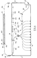
- FIG. 2 shows the connection device with the three cassettes 40b, 40c, 40d in the raised position towards the rear to free access to the lower cassette 40a.
- Each cassette comprises means for accommodating reserve lengths of optical fibers, intended for subsequent splicing or connection operations, and means for storing the splices of the connected fibers.
- each cassette comprises two drums 41 and 42 on which are coiled the optical fibers arriving and leaving respectively by the lateral inlets 44 and outlets 45 and a housing 43 located between the two drums 41 and 42, having a plurality of 'juxtaposed notches, oriented parallel to the Y axis, to store the splices of the connected optical fibers.
- the drums 41 and 42 have a diameter slightly less than the width of the cassettes and are located respectively on the latter near the raised side edges 47b.
- the aforementioned retaining tabs 47c extend two by two above the optical fibers wound on the drums 41 and 42, between the latter and the longitudinal edges 47a and lateral 47b to hold the optical fibers in place when the cassettes are tilted.
- the diameter of the drums 41 and 42 makes it possible to respect the radius of curvature imposed on the coiling of the optical fibers.
- the cable C for supplying the optical fibers is fixed, in a manner known per se, by means of one or more collars, to the upright 2 of the frame, above the horizontal plane containing the upper horizontal edges of the walls 11, 12 and 16.
- the optical fibers extend bare out of the cable C from its point of attachment to the upright 2 downwards and penetrate into the protected space 30 for the flourishing of the fibers inside the chassis through the opening 15, as shown in FIG. 2.
- the optical fibers are guided in this protected space 30 by guide stirrups 31a, ..., 31i made of plastic material, each comprising a base to be bonded to a wall of the chassis and two branches each connecting at one end perpendicular to this base.
- the two branches define at their free end two ramps converging towards the base, able to deform elastically in separation from one another to allow the insertion of optical fibers between the branches and their retention on the stirrup guide.
- the bottom 13 of the chassis 10 comprises a first series of four guide stirrups arranged to guide the optical fibers from the opening 15 towards the lateral entry 44 of the cassettes, situated on the side of the opening 15.
- the optical fibers extend from the opening 15 along an inflected line 201, concave then convex to the right in the drawing, that is ie towards the side wall 12, up to a first stirrup 31a.
- a second 31b and third 31c guide stirrups are arranged on the bottom wall 13 for guiding the optical fibers from the first guide stirrup 31a to a fourth guide stirrup 31d arranged on the rear wall 16, along a line 202 describing a U whose concavity faces the side wall 12.
- the third stirrup 31c is positioned in the bottom of the line 202.
- a fifth guide stirrup 31e is fixed on the side wall 12 to guide the optical fibers from the fourth stirrup guide 31d towards the lateral entry 44 of the cassettes along an ascending line 203 running along the rear wall 16 and then along a line 204 describing a U whose concavity is oriented towards the side wall 11.
- a second series of guide stirrups is arranged to guide the optical fibers from the lateral outlet 45 of the cassettes towards the front wall 14 or towards the opening 15, depending on whether these optical fibers are intended to be connected to connectors arranged on the front wall 14 or to be directed towards the outside of the chassis 10.
- a sixth guide stirrup 31f is disposed on the side wall 11 for guiding the optical fibers from the side outlet 45 of the cassettes towards the protected space 30 d blooming of the optical fibers along a line 205 describing a U whose concavity is turned towards the side wall 12 of the chassis 10.
- a seventh guide stirrup 31g is arranged on the rear wall 16 to guide the optical fibers from the sixth guide stirrup 31f along a straight line 206 extending downward.
- the optical fibers to be directed towards the front wall 14 are guided, from the seventh guide stirrup 31g, by an eighth guide stirrup 31h along a line 207 describing a 90 ° turn towards the front wall 14 and the optical fibers to be directed towards the opening 15 are guided by a ninth guide stirrup 31i towards the aforementioned second guide stirrup 31b, along an inflected line 208 concave then convex towards the side wall 11, and whose inflection point is located at the level of the ninth stirrup guide 31i.
- the optical fibers then join the opening 15 along the bent line 201.
- the rearward pivoting of the cassettes takes place at an angle greater than 90 ° so that the latter are held in the open position stably under the effect of their own weight.
- Means are provided for removably securing the cassettes. This joining is preferably carried out, as shown, by means of strips of fabric with loops 49a, glued to the upper face of the drums 41 and 42 of the cassettes 40a, 40b, 40c and by means of strips of fabric with hooks 49b, glued on the underside of the bottom wall of the frames of the cassettes 40b, 40c and 40d, capable of coming to hang on the strips of fabric 49a of the cassette immediately below.
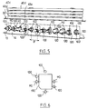
- the front wall 14 is provided, as shown in Figures 5 and 6, with a plurality of identical cutouts 130 regularly spaced intended for mounting connectors on this wall.
- the shape of the cutout 130 is chosen so as to allow mounting on the front wall 14 of several different types of connectors.
- each cutout 130 is rectangular with a truncated corner and it is bordered, vertically by two holes 100 located on either side of the cutout, and laterally by two pairs of holes 110 and 120 symmetrical with respect to the intersection perpendicular bisectors connecting the opposite sides of the cutout 130.
- FIG. 3 shows the connection device equipped on its front wall 14 with two connectors connected respectively, by cables C1 and C2, to a laser source and an opto-electronic conversion device.
- connection device offers a large storage capacity for optical fibers in a small footprint, ensures stable and protected housing of the optical fibers and high reliability of the connection.
- the cassettes are pivoted from the front relative to the operator so that the handling of optical fibers and splices is easy.
- the optical fibers extend bare between the supply or departure cable C and the cassettes as well as between the cassettes and the connection connectors without it being necessary to protect or guide them by a tube as is the case of the known device to which reference is made in the preamble.
Landscapes
- Physics & Mathematics (AREA)
- General Physics & Mathematics (AREA)
- Optics & Photonics (AREA)
- Light Guides In General And Applications Therefor (AREA)
- Mechanical Coupling Of Light Guides (AREA)
Applications Claiming Priority (2)
| Application Number | Priority Date | Filing Date | Title |
|---|---|---|---|
| FR9311405 | 1993-09-24 | ||
| FR9311405A FR2710419B1 (fr) | 1993-09-24 | 1993-09-24 | Dispositif de raccordement pour fibres optiques. |
Publications (2)
| Publication Number | Publication Date |
|---|---|
| EP0645657A1 true EP0645657A1 (de) | 1995-03-29 |
| EP0645657B1 EP0645657B1 (de) | 2000-01-26 |
Family
ID=9451214
Family Applications (1)
| Application Number | Title | Priority Date | Filing Date |
|---|---|---|---|
| EP94402110A Expired - Lifetime EP0645657B1 (de) | 1993-09-24 | 1994-09-22 | Vorrichtung zum Verbinden optischer Fasern |
Country Status (3)
| Country | Link |
|---|---|
| EP (1) | EP0645657B1 (de) |
| DE (1) | DE69422768T2 (de) |
| FR (1) | FR2710419B1 (de) |
Cited By (4)
| Publication number | Priority date | Publication date | Assignee | Title |
|---|---|---|---|---|
| EP0922979A1 (de) * | 1997-12-12 | 1999-06-16 | BICC KWO Kabel GmbH | Abschlusseinheit für Lichtwellenleiter-Kabel |
| WO2003005095A3 (en) * | 2001-07-06 | 2003-10-23 | Adc Telecommunications Inc | Cable management panel with sliding drawer and methods |
| AU2002356747B2 (en) * | 2002-01-03 | 2007-12-20 | Ccs Technology, Inc. | Splicing cassette management system for light wave guides |
| WO2009103382A1 (de) * | 2008-02-22 | 2009-08-27 | Adc Gmbh | Glasfaser-anschlussmodul |
Families Citing this family (3)
| Publication number | Priority date | Publication date | Assignee | Title |
|---|---|---|---|---|
| DE102013012975B4 (de) * | 2013-08-03 | 2019-03-28 | Langmatz Gmbh | Glasfaser-Verteilungsrahmen mit Patch-Kassetten |
| DE102015118501A1 (de) * | 2015-10-29 | 2016-10-27 | Reichle & De-Massari Ag | Kabelmanagementvorrichtung und Verfahren mit einer Kabelmanagementvorrichtung |
| US10670822B2 (en) | 2017-06-28 | 2020-06-02 | Afl Telecommunications Llc | High density patch panel with modular cassettes |
Citations (3)
| Publication number | Priority date | Publication date | Assignee | Title |
|---|---|---|---|---|
| EP0356942A2 (de) * | 1988-08-29 | 1990-03-07 | Gte Control Devices Of Puerto Rico Incorporated | Verteilerconsole für Lichtwellenleiter |
| EP0549963A2 (de) * | 1991-12-30 | 1993-07-07 | Reichle + De-Massari AG Elektro-Ingenieure | Schaltschrank für Glasfaserkabel-Endgeräte |
| EP0557190A1 (de) * | 1992-02-21 | 1993-08-25 | Alcatel Cable Interface | Zusammenbau von gestapelten Gelenkmodulen |
Family Cites Families (1)
| Publication number | Priority date | Publication date | Assignee | Title |
|---|---|---|---|---|
| FR2646928B1 (fr) * | 1989-05-11 | 1993-12-24 | Etat Francais Cnet | Module et boitier de raccordement de cables a fibres optiques |
-
1993
- 1993-09-24 FR FR9311405A patent/FR2710419B1/fr not_active Expired - Fee Related
-
1994
- 1994-09-22 EP EP94402110A patent/EP0645657B1/de not_active Expired - Lifetime
- 1994-09-22 DE DE69422768T patent/DE69422768T2/de not_active Expired - Lifetime
Patent Citations (3)
| Publication number | Priority date | Publication date | Assignee | Title |
|---|---|---|---|---|
| EP0356942A2 (de) * | 1988-08-29 | 1990-03-07 | Gte Control Devices Of Puerto Rico Incorporated | Verteilerconsole für Lichtwellenleiter |
| EP0549963A2 (de) * | 1991-12-30 | 1993-07-07 | Reichle + De-Massari AG Elektro-Ingenieure | Schaltschrank für Glasfaserkabel-Endgeräte |
| EP0557190A1 (de) * | 1992-02-21 | 1993-08-25 | Alcatel Cable Interface | Zusammenbau von gestapelten Gelenkmodulen |
Cited By (15)
| Publication number | Priority date | Publication date | Assignee | Title |
|---|---|---|---|---|
| EP0922979A1 (de) * | 1997-12-12 | 1999-06-16 | BICC KWO Kabel GmbH | Abschlusseinheit für Lichtwellenleiter-Kabel |
| US7480438B2 (en) | 2001-07-06 | 2009-01-20 | Adc Telecommunications, Inc. | Cable management panel with sliding drawer and methods |
| US7664362B2 (en) | 2001-07-06 | 2010-02-16 | Adc Telecommunications, Inc. | Cable management panel with sliding drawer and methods |
| US7231125B2 (en) | 2001-07-06 | 2007-06-12 | Adc Telecommunications, Inc. | Cable management panel with sliding drawer and methods |
| US11320619B2 (en) | 2001-07-06 | 2022-05-03 | Commscope Technologies Llc | Cable management panel with sliding drawer and methods |
| US7373071B2 (en) | 2001-07-06 | 2008-05-13 | Adc Telecommunications, Inc. | Cable management panel with sliding drawer and methods |
| WO2003005095A3 (en) * | 2001-07-06 | 2003-10-23 | Adc Telecommunications Inc | Cable management panel with sliding drawer and methods |
| US10989889B2 (en) | 2001-07-06 | 2021-04-27 | Commscope Technologies Llc | Cable management panel with sliding drawer and methods |
| US7079744B2 (en) | 2001-07-06 | 2006-07-18 | Adc Telecommunications, Inc. | Cable management panel with sliding drawer and methods |
| US8078029B2 (en) | 2001-07-06 | 2011-12-13 | Adc Telecommunications, Inc. | Cable management panel with sliding drawer and methods |
| US10146023B2 (en) | 2001-07-06 | 2018-12-04 | Commscope Technologies Llc | Cable management panel with sliding drawer and methods |
| US9442267B2 (en) | 2001-07-06 | 2016-09-13 | Commscope Technologies Llc | Cable management panel with sliding drawer and methods |
| AU2002356747B2 (en) * | 2002-01-03 | 2007-12-20 | Ccs Technology, Inc. | Splicing cassette management system for light wave guides |
| US8467652B2 (en) | 2008-02-22 | 2013-06-18 | Adc Gmbh | Glass fiber connection module |
| WO2009103382A1 (de) * | 2008-02-22 | 2009-08-27 | Adc Gmbh | Glasfaser-anschlussmodul |
Also Published As
| Publication number | Publication date |
|---|---|
| EP0645657B1 (de) | 2000-01-26 |
| DE69422768D1 (de) | 2000-03-02 |
| FR2710419A1 (fr) | 1995-03-31 |
| FR2710419B1 (fr) | 1995-12-15 |
| DE69422768T2 (de) | 2000-06-29 |
Similar Documents
| Publication | Publication Date | Title |
|---|---|---|
| EP0397587B1 (de) | Modul und Kabelverbindungsgehäuse mit optischen Fasern | |
| EP0116480B1 (de) | Gehäuse zum Verbinden und Mischen optischer Fasern | |
| EP0978746B1 (de) | Verbindungsvorrichtung für faseroptische Kabel | |
| EP1315009B1 (de) | Anordnung zur Verteilung und Verbindung optischer Fasern für ein optisches Querverbindungssystem | |
| EP0538164A1 (de) | Verteilergestell für optische Kabel hoher Kapazität | |
| FR2588094A1 (fr) | Assemblage de plateaux d'agencement pour l'emmagasinage de raccords de fibres optiques | |
| FR2531544A1 (fr) | Tete de cable optique | |
| WO1998004860A1 (fr) | Eclisse d'assemblage pour tronçons de chemins de cables et tronçons de chemins de cables obtenus | |
| EP0744640A1 (de) | Verbindungsgehäuse für optische Fasern | |
| EP0348278A1 (de) | Verteil- und Verbindungsvorrichtung für optische Fasern | |
| FR2663917A1 (fr) | Dispositif modulaire pour le stockage de reserves de support de transmission sur des liaisons, notamment a fibre optique. | |
| FR2797528A1 (fr) | Dispositif de guidage d'au moins un element longiligne souple, tel que cable ou autre, a contour substantiellement ferme | |
| FR2730319A1 (fr) | Boitier d'epissure pour fibres optiques | |
| EP1026530A1 (de) | Verteiler für optische Fasern | |
| EP0402281A1 (de) | Verbindungselement für Wellrohre | |
| FR2959383A1 (fr) | Dispositif de connexion et/ou de stockage de cables muni d'un element de charniere | |
| EP0645657B1 (de) | Vorrichtung zum Verbinden optischer Fasern | |
| FR2688897A1 (fr) | Prise optique. | |
| FR2953655A1 (fr) | Dispositif de fixation destine a la fixation d'un accessoire sur un chemin de cables en fils | |
| FR2694642A1 (fr) | Dispositif de raccordement d'au moins un câble de transmission à des équipements électroniques. | |
| FR2743899A1 (fr) | Dispositif d'organisation de raccordements de fibres optiques | |
| FR2538695A1 (fr) | Distributeur de feuilles de papier a chargement vertical et a distribution frontale | |
| FR2566756A1 (fr) | Boite de lovage pour cable | |
| EP0968674B1 (de) | Zusammenstellungsweise von Halterungen, Verkaufsständern oder Verpackungen | |
| FR2670586A1 (fr) | Boite de raccordement pour cables a fibres optiques. |
Legal Events
| Date | Code | Title | Description |
|---|---|---|---|
| PUAI | Public reference made under article 153(3) epc to a published international application that has entered the european phase |
Free format text: ORIGINAL CODE: 0009012 |
|
| AK | Designated contracting states |
Kind code of ref document: A1 Designated state(s): DE GB IT |
|
| 17P | Request for examination filed |
Effective date: 19950911 |
|
| RBV | Designated contracting states (corrected) |
Designated state(s): DE GB IT |
|
| 17Q | First examination report despatched |
Effective date: 19970704 |
|
| GRAG | Despatch of communication of intention to grant |
Free format text: ORIGINAL CODE: EPIDOS AGRA |
|
| GRAG | Despatch of communication of intention to grant |
Free format text: ORIGINAL CODE: EPIDOS AGRA |
|
| GRAG | Despatch of communication of intention to grant |
Free format text: ORIGINAL CODE: EPIDOS AGRA |
|
| GRAH | Despatch of communication of intention to grant a patent |
Free format text: ORIGINAL CODE: EPIDOS IGRA |
|
| GRAH | Despatch of communication of intention to grant a patent |
Free format text: ORIGINAL CODE: EPIDOS IGRA |
|
| GRAA | (expected) grant |
Free format text: ORIGINAL CODE: 0009210 |
|
| AK | Designated contracting states |
Kind code of ref document: B1 Designated state(s): DE GB IT |
|
| ITF | It: translation for a ep patent filed | ||
| GBT | Gb: translation of ep patent filed (gb section 77(6)(a)/1977) |
Effective date: 20000127 |
|
| REF | Corresponds to: |
Ref document number: 69422768 Country of ref document: DE Date of ref document: 20000302 |
|
| PLBE | No opposition filed within time limit |
Free format text: ORIGINAL CODE: 0009261 |
|
| STAA | Information on the status of an ep patent application or granted ep patent |
Free format text: STATUS: NO OPPOSITION FILED WITHIN TIME LIMIT |
|
| 26N | No opposition filed | ||
| REG | Reference to a national code |
Ref country code: GB Ref legal event code: IF02 |
|
| PGFP | Annual fee paid to national office [announced via postgrant information from national office to epo] |
Ref country code: DE Payment date: 20110902 Year of fee payment: 18 Ref country code: GB Payment date: 20110830 Year of fee payment: 18 |
|
| PGFP | Annual fee paid to national office [announced via postgrant information from national office to epo] |
Ref country code: IT Payment date: 20110826 Year of fee payment: 18 |
|
| GBPC | Gb: european patent ceased through non-payment of renewal fee |
Effective date: 20120922 |
|
| REG | Reference to a national code |
Ref country code: DE Ref legal event code: R119 Ref document number: 69422768 Country of ref document: DE Effective date: 20130403 |
|
| PG25 | Lapsed in a contracting state [announced via postgrant information from national office to epo] |
Ref country code: DE Free format text: LAPSE BECAUSE OF NON-PAYMENT OF DUE FEES Effective date: 20130403 Ref country code: GB Free format text: LAPSE BECAUSE OF NON-PAYMENT OF DUE FEES Effective date: 20120922 |
|
| PG25 | Lapsed in a contracting state [announced via postgrant information from national office to epo] |
Ref country code: IT Free format text: LAPSE BECAUSE OF NON-PAYMENT OF DUE FEES Effective date: 20120922 |