EP0645854A1 - Bürstenhalter für einen elektrischen Kleinmotor - Google Patents
Bürstenhalter für einen elektrischen Kleinmotor Download PDFInfo
- Publication number
- EP0645854A1 EP0645854A1 EP94306693A EP94306693A EP0645854A1 EP 0645854 A1 EP0645854 A1 EP 0645854A1 EP 94306693 A EP94306693 A EP 94306693A EP 94306693 A EP94306693 A EP 94306693A EP 0645854 A1 EP0645854 A1 EP 0645854A1
- Authority
- EP
- European Patent Office
- Prior art keywords
- brush
- tube
- brush arm
- fingers
- electric motor
- Prior art date
- Legal status (The legal status is an assumption and is not a legal conclusion. Google has not performed a legal analysis and makes no representation as to the accuracy of the status listed.)
- Withdrawn
Links
- 239000000853 adhesive Substances 0.000 description 5
- 230000001070 adhesive effect Effects 0.000 description 5
- 239000011248 coating agent Substances 0.000 description 2
- 238000000576 coating method Methods 0.000 description 2
- 239000004519 grease Substances 0.000 description 2
- 239000000463 material Substances 0.000 description 2
- 238000000034 method Methods 0.000 description 2
- 238000007493 shaping process Methods 0.000 description 2
- OKTJSMMVPCPJKN-UHFFFAOYSA-N Carbon Chemical compound [C] OKTJSMMVPCPJKN-UHFFFAOYSA-N 0.000 description 1
- 229910052799 carbon Inorganic materials 0.000 description 1
- 238000011109 contamination Methods 0.000 description 1
- 239000000123 paper Substances 0.000 description 1
- 239000005060 rubber Substances 0.000 description 1
Images

Classifications
-
- H—ELECTRICITY
- H01—ELECTRIC ELEMENTS
- H01R—ELECTRICALLY-CONDUCTIVE CONNECTIONS; STRUCTURAL ASSOCIATIONS OF A PLURALITY OF MUTUALLY-INSULATED ELECTRICAL CONNECTING ELEMENTS; COUPLING DEVICES; CURRENT COLLECTORS
- H01R39/00—Rotary current collectors, distributors or interrupters
- H01R39/02—Details for dynamo electric machines
- H01R39/38—Brush holders
- H01R39/39—Brush holders wherein the brush is fixedly mounted in the holder
-
- H—ELECTRICITY
- H02—GENERATION; CONVERSION OR DISTRIBUTION OF ELECTRIC POWER
- H02K—DYNAMO-ELECTRIC MACHINES
- H02K13/00—Structural associations of current collectors with motors or generators, e.g. brush mounting plates or connections to windings; Disposition of current collectors in motors or generators; Arrangements for improving commutation
- H02K13/10—Arrangements of brushes or commutators specially adapted for improving commutation
Definitions
- This invention relates to brush gear for a miniature electric motor and in particular to brush gear incorporating vibration dampening means.
- the present invention seeks to mitigate these disadvantages by providing the vibration dampening means in the form of a tube which is shrunk onto the brush arm. This provides good fixing of the tube to the brush arm which may be further enhanced by adhesive.
- the structure of the tube means that adhesive is not essential and thus adhesive failure will not result in the dampening means separating from the brush arm as in the prior art.
- the present invention provides brush gear for a miniature electric motor comprising: an elongate brush arm having a proximal end and a distal end, the proximal end being connected to a brush holder and the distal end being adapted for sliding contact with a commutator; and vibration dampening means applied to the brush arm intermediate the proximal and distal ends, wherein the vibration dampening means comprises a tube shrunk onto the brush arm.
- the brush arm may be of the finger brush type in which the distal end is divided into a number of fingers by slits extending into an intermediate portion and the dampening means is a single tube extending over the root of the fingers or a plurality of tubes fitted to respective fingers.
- the invention also extends to a miniature electric motor incorporating such brush gear.
- the first embodiment of the invention includes a brush arm 10 for a miniature electric motor.
- the brush arm is elongate in form with a proximal end 11 and a distal end 12.
- the proximal end is connected to a brush holder 20 by upset rivets 21 as is known.
- the distal end is adapted to make sliding contact with a commutator. This may be by way of a carbon brush or suitable shaping and/or coating of the distal end of the brush arm as is also commonly known.
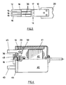
- vibration dampening means in the form of a tube 30 which is shrunk onto the brush arm.
- the tube 30 is in its enlarged form before being fitted to the brush arm 10.
- the enlarged size of the tube allows the tube to be easily and quickly placed in position over an intermediate portion 14 of the brush arm and then shrunk to size using known techniques.
- a particularly convenient method is to use an elastomeric tubing which has been expanded and shrinks on application of heat to fit the tube to the brush arm.
- One such tubing is known as HEAT SHRINK tubing by Raychem Industries. This tubing is available with or without an inner coating of adhesive.
- Figure 2 shows the tube so shrunk into position on a finger leaf brush.
- a finger leaf brush is a brush arm having a number of slits 15 dividing the distal end of the brush arm into a plurality of fingers 16 having their roots 17 in the intermediate portion 14.
- the tube is shown covering the roots of the fingers and extending a short distance either way. The exact extent of the tube will depend on dampening requirements.
- FIG 3 an alternative embodiment is shown again using a finger brush.
- the fingers 16 have separate tubes 30. This allows greater control over the degree of dampening provided for each finger individually and can be used to have fingers dampened for different resonance frequencies.
- the dampening rate depends on the length of the tube, the thickness of the tube and the material of the tube.
- the present invention also encompasses a miniature motor incorporating brush gear as described and Figure 4 illustrates, in partial section, one such motor of the permanent magnet direct current type.
- the motor has a can-like housing 40, two permanent magnets 41 forming a stator, a wound rotor 42 including a commutator 43 and an end cap 44 closing an open end of the casing.
- the end cap supports motor terminals 45 and the brush gear 50.
- the brush gear electrically connects the motor terminals to the commutator 43.
Landscapes
- Engineering & Computer Science (AREA)
- Power Engineering (AREA)
- Motor Or Generator Current Collectors (AREA)
- Dc Machiner (AREA)
- Connection Of Motors, Electrical Generators, Mechanical Devices, And The Like (AREA)
- Motor Or Generator Frames (AREA)
Applications Claiming Priority (2)
| Application Number | Priority Date | Filing Date | Title |
|---|---|---|---|
| GB939319740A GB9319740D0 (en) | 1993-09-24 | 1993-09-24 | Brush gear for a miniature electric motor |
| GB9319740 | 1993-09-24 |
Publications (1)
| Publication Number | Publication Date |
|---|---|
| EP0645854A1 true EP0645854A1 (de) | 1995-03-29 |
Family
ID=10742479
Family Applications (1)
| Application Number | Title | Priority Date | Filing Date |
|---|---|---|---|
| EP94306693A Withdrawn EP0645854A1 (de) | 1993-09-24 | 1994-09-13 | Bürstenhalter für einen elektrischen Kleinmotor |
Country Status (4)
| Country | Link |
|---|---|
| EP (1) | EP0645854A1 (de) |
| JP (1) | JP3009173U (de) |
| CN (1) | CN1104383A (de) |
| GB (1) | GB9319740D0 (de) |
Cited By (4)
| Publication number | Priority date | Publication date | Assignee | Title |
|---|---|---|---|---|
| EP1193839A3 (de) * | 2000-08-21 | 2003-11-12 | Johnson Electric S.A. | Endkappenanordnung |
| WO2006072491A1 (de) * | 2004-12-30 | 2006-07-13 | Robert Bosch Gmbh | Bürstenhalter für eine elektrische maschine |
| DE102011051090A1 (de) * | 2011-06-15 | 2012-12-20 | Valeo Systèmes d'Essuyage | Antriebsvorrichtung sowie Scheibenwischervorrichtung mit Antriebsvorrichtung |
| US10833467B2 (en) * | 2017-11-06 | 2020-11-10 | Schleifring Gmbh | Vibration absorbing device for slip-ring brushes |
Citations (3)
| Publication number | Priority date | Publication date | Assignee | Title |
|---|---|---|---|---|
| FR2321210A1 (fr) * | 1975-08-13 | 1977-03-11 | Bosch Gmbh Robert | Porte-balais pour machines electriques, notamment pour alternateurs triphases de vehicules |
| GB2184612A (en) * | 1985-11-28 | 1987-06-24 | Mabuchi Motor Co | Miniature electric motor brush gear |
| US4849582A (en) * | 1987-10-28 | 1989-07-18 | Bell Of Pennsylvania | Heat shrinkable strain relief device and method of forming same |
-
1993
- 1993-09-24 GB GB939319740A patent/GB9319740D0/en active Pending
-
1994
- 1994-09-13 EP EP94306693A patent/EP0645854A1/de not_active Withdrawn
- 1994-09-15 CN CN 94116125 patent/CN1104383A/zh active Pending
- 1994-09-19 JP JP1994011592U patent/JP3009173U/ja not_active Expired - Lifetime
Patent Citations (3)
| Publication number | Priority date | Publication date | Assignee | Title |
|---|---|---|---|---|
| FR2321210A1 (fr) * | 1975-08-13 | 1977-03-11 | Bosch Gmbh Robert | Porte-balais pour machines electriques, notamment pour alternateurs triphases de vehicules |
| GB2184612A (en) * | 1985-11-28 | 1987-06-24 | Mabuchi Motor Co | Miniature electric motor brush gear |
| US4849582A (en) * | 1987-10-28 | 1989-07-18 | Bell Of Pennsylvania | Heat shrinkable strain relief device and method of forming same |
Cited By (5)
| Publication number | Priority date | Publication date | Assignee | Title |
|---|---|---|---|---|
| EP1193839A3 (de) * | 2000-08-21 | 2003-11-12 | Johnson Electric S.A. | Endkappenanordnung |
| WO2006072491A1 (de) * | 2004-12-30 | 2006-07-13 | Robert Bosch Gmbh | Bürstenhalter für eine elektrische maschine |
| DE102011051090A1 (de) * | 2011-06-15 | 2012-12-20 | Valeo Systèmes d'Essuyage | Antriebsvorrichtung sowie Scheibenwischervorrichtung mit Antriebsvorrichtung |
| EP2720913A1 (de) * | 2011-06-15 | 2014-04-23 | Valeo Systèmes d'Essuyage | Antriebsvorrichtung sowie scheibenwischervorrichtung mit antriebsvorrichtung |
| US10833467B2 (en) * | 2017-11-06 | 2020-11-10 | Schleifring Gmbh | Vibration absorbing device for slip-ring brushes |
Also Published As
| Publication number | Publication date |
|---|---|
| CN1104383A (zh) | 1995-06-28 |
| JP3009173U (ja) | 1995-03-28 |
| GB9319740D0 (en) | 1993-11-10 |
Similar Documents
| Publication | Publication Date | Title |
|---|---|---|
| EP0863602B1 (de) | Läufer für einen Elektromotor | |
| US5023502A (en) | Switched reluctance motor rotor | |
| EP0917273B1 (de) | Statorwickelverfahren und Statorwickelsystem | |
| EP1174982A3 (de) | Stator für rotierende elektrische Maschinen oder Linearmotoren | |
| JPS6289458A (ja) | 電気モ−タ | |
| EP0957564A3 (de) | Zusammengestellte Rotor- und Statoranordnung | |
| EP0509683B1 (de) | Miniaturmotor | |
| GB2032708A (en) | A stator for electric motors | |
| GB2184612A (en) | Miniature electric motor brush gear | |
| CN1336029A (zh) | 小型电动机 | |
| US5714826A (en) | Electric motor | |
| JP3009173U (ja) | 小型電動機用のブラシギア | |
| US4983872A (en) | Brush gear for a permanent magnet motor | |
| EP1176697A3 (de) | Erregerwicklung und Wicklungsverfahren | |
| US5053657A (en) | Miniature motor | |
| EP0296715A1 (de) | Gehäuse eines elektrischen Motors und Herstellungsverfahren | |
| US4218630A (en) | Insulation stator for end turn windings of electric rotary machine | |
| EP1478078A3 (de) | Elektromotor | |
| AU2003240760A1 (en) | Winding for a dynamo-electric machine | |
| GB2173648A (en) | Electric motors and their assembly | |
| JP3871279B2 (ja) | 電動工具 | |
| EP0759652A1 (de) | Kollektor | |
| US4372039A (en) | Coil guide member for coil insertion tool | |
| GB2196489A (en) | Electric motor | |
| GB2214358A (en) | A brush leaf assembly for electric motor |
Legal Events
| Date | Code | Title | Description |
|---|---|---|---|
| PUAI | Public reference made under article 153(3) epc to a published international application that has entered the european phase |
Free format text: ORIGINAL CODE: 0009012 |
|
| AK | Designated contracting states |
Kind code of ref document: A1 Designated state(s): DE ES FR GB IT |
|
| STAA | Information on the status of an ep patent application or granted ep patent |
Free format text: STATUS: THE APPLICATION IS DEEMED TO BE WITHDRAWN |
|
| 18D | Application deemed to be withdrawn |
Effective date: 19950930 |