EP0646416A1 - Filtre chargé bipolairement et méthode pour son utilisation - Google Patents
Filtre chargé bipolairement et méthode pour son utilisation Download PDFInfo
- Publication number
- EP0646416A1 EP0646416A1 EP94306596A EP94306596A EP0646416A1 EP 0646416 A1 EP0646416 A1 EP 0646416A1 EP 94306596 A EP94306596 A EP 94306596A EP 94306596 A EP94306596 A EP 94306596A EP 0646416 A1 EP0646416 A1 EP 0646416A1
- Authority
- EP
- European Patent Office
- Prior art keywords
- high voltage
- ionizer
- filter
- voltage source
- period
- Prior art date
- Legal status (The legal status is an assumption and is not a legal conclusion. Google has not performed a legal analysis and makes no representation as to the accuracy of the status listed.)
- Withdrawn
Links
- 238000000034 method Methods 0.000 title claims abstract description 11
- 238000011144 upstream manufacturing Methods 0.000 claims abstract description 8
- 230000003213 activating effect Effects 0.000 claims abstract description 6
- 238000001914 filtration Methods 0.000 claims abstract description 6
- 239000013618 particulate matter Substances 0.000 claims abstract 4
- 230000001351 cycling effect Effects 0.000 claims abstract 3
- 239000012530 fluid Substances 0.000 claims abstract 3
- 238000011045 prefiltration Methods 0.000 claims description 8
- 239000002245 particle Substances 0.000 description 35
- 239000000835 fiber Substances 0.000 description 29
- MQIUGAXCHLFZKX-UHFFFAOYSA-N Di-n-octyl phthalate Natural products CCCCCCCCOC(=O)C1=CC=CC=C1C(=O)OCCCCCCCC MQIUGAXCHLFZKX-UHFFFAOYSA-N 0.000 description 14
- BJQHLKABXJIVAM-UHFFFAOYSA-N bis(2-ethylhexyl) phthalate Chemical compound CCCCC(CC)COC(=O)C1=CC=CC=C1C(=O)OCC(CC)CCCC BJQHLKABXJIVAM-UHFFFAOYSA-N 0.000 description 14
- 230000000694 effects Effects 0.000 description 14
- 239000000428 dust Substances 0.000 description 11
- 238000012360 testing method Methods 0.000 description 10
- 230000005684 electric field Effects 0.000 description 8
- 239000000843 powder Substances 0.000 description 7
- -1 pollen Substances 0.000 description 6
- 239000012717 electrostatic precipitator Substances 0.000 description 5
- 230000001965 increasing effect Effects 0.000 description 5
- 239000012212 insulator Substances 0.000 description 5
- 239000000463 material Substances 0.000 description 5
- 230000007246 mechanism Effects 0.000 description 5
- 239000004743 Polypropylene Substances 0.000 description 4
- 238000004140 cleaning Methods 0.000 description 4
- 229910052751 metal Inorganic materials 0.000 description 4
- 239000002184 metal Substances 0.000 description 4
- 229920001155 polypropylene Polymers 0.000 description 4
- XLYOFNOQVPJJNP-UHFFFAOYSA-N water Substances O XLYOFNOQVPJJNP-UHFFFAOYSA-N 0.000 description 4
- 230000008901 benefit Effects 0.000 description 3
- 230000008021 deposition Effects 0.000 description 3
- 239000011347 resin Substances 0.000 description 3
- 229920005989 resin Polymers 0.000 description 3
- 238000010586 diagram Methods 0.000 description 2
- 238000007599 discharging Methods 0.000 description 2
- 230000002708 enhancing effect Effects 0.000 description 2
- 239000010419 fine particle Substances 0.000 description 2
- 235000013312 flour Nutrition 0.000 description 2
- 238000012423 maintenance Methods 0.000 description 2
- 238000012856 packing Methods 0.000 description 2
- 238000003380 quartz crystal microbalance Methods 0.000 description 2
- WFKWXMTUELFFGS-UHFFFAOYSA-N tungsten Chemical compound [W] WFKWXMTUELFFGS-UHFFFAOYSA-N 0.000 description 2
- 210000002268 wool Anatomy 0.000 description 2
- 239000004698 Polyethylene Substances 0.000 description 1
- 238000007792 addition Methods 0.000 description 1
- 239000000443 aerosol Substances 0.000 description 1
- 238000013459 approach Methods 0.000 description 1
- 230000003416 augmentation Effects 0.000 description 1
- 230000015572 biosynthetic process Effects 0.000 description 1
- 206010061592 cardiac fibrillation Diseases 0.000 description 1
- 210000004027 cell Anatomy 0.000 description 1
- 230000008859 change Effects 0.000 description 1
- 238000006243 chemical reaction Methods 0.000 description 1
- 238000012217 deletion Methods 0.000 description 1
- 230000037430 deletion Effects 0.000 description 1
- 210000001787 dendrite Anatomy 0.000 description 1
- 238000013461 design Methods 0.000 description 1
- 239000003989 dielectric material Substances 0.000 description 1
- 238000009792 diffusion process Methods 0.000 description 1
- 230000003292 diminished effect Effects 0.000 description 1
- 238000009429 electrical wiring Methods 0.000 description 1
- 239000004744 fabric Substances 0.000 description 1
- 230000002600 fibrillogenic effect Effects 0.000 description 1
- 239000002657 fibrous material Substances 0.000 description 1
- 239000011888 foil Substances 0.000 description 1
- 239000003517 fume Substances 0.000 description 1
- 239000003365 glass fiber Substances 0.000 description 1
- 230000006872 improvement Effects 0.000 description 1
- 150000002500 ions Chemical class 0.000 description 1
- 230000001788 irregular Effects 0.000 description 1
- 238000005259 measurement Methods 0.000 description 1
- 238000012986 modification Methods 0.000 description 1
- 230000004048 modification Effects 0.000 description 1
- 239000004033 plastic Substances 0.000 description 1
- 229920003023 plastic Polymers 0.000 description 1
- 229920000573 polyethylene Polymers 0.000 description 1
- 230000008569 process Effects 0.000 description 1
- 230000001846 repelling effect Effects 0.000 description 1
- 230000000717 retained effect Effects 0.000 description 1
- 238000006467 substitution reaction Methods 0.000 description 1
- 230000002459 sustained effect Effects 0.000 description 1
- 229910052721 tungsten Inorganic materials 0.000 description 1
- 239000010937 tungsten Substances 0.000 description 1
Images



Classifications
-
- B—PERFORMING OPERATIONS; TRANSPORTING
- B03—SEPARATION OF SOLID MATERIALS USING LIQUIDS OR USING PNEUMATIC TABLES OR JIGS; MAGNETIC OR ELECTROSTATIC SEPARATION OF SOLID MATERIALS FROM SOLID MATERIALS OR FLUIDS; SEPARATION BY HIGH-VOLTAGE ELECTRIC FIELDS
- B03C—MAGNETIC OR ELECTROSTATIC SEPARATION OF SOLID MATERIALS FROM SOLID MATERIALS OR FLUIDS; SEPARATION BY HIGH-VOLTAGE ELECTRIC FIELDS
- B03C3/00—Separating dispersed particles from gases or vapour, e.g. air, by electrostatic effect
- B03C3/017—Combinations of electrostatic separation with other processes, not otherwise provided for
- B03C3/0175—Amassing particles by electric fields, e.g. agglomeration
-
- B—PERFORMING OPERATIONS; TRANSPORTING
- B03—SEPARATION OF SOLID MATERIALS USING LIQUIDS OR USING PNEUMATIC TABLES OR JIGS; MAGNETIC OR ELECTROSTATIC SEPARATION OF SOLID MATERIALS FROM SOLID MATERIALS OR FLUIDS; SEPARATION BY HIGH-VOLTAGE ELECTRIC FIELDS
- B03C—MAGNETIC OR ELECTROSTATIC SEPARATION OF SOLID MATERIALS FROM SOLID MATERIALS OR FLUIDS; SEPARATION BY HIGH-VOLTAGE ELECTRIC FIELDS
- B03C3/00—Separating dispersed particles from gases or vapour, e.g. air, by electrostatic effect
- B03C3/02—Plant or installations having external electricity supply
- B03C3/04—Plant or installations having external electricity supply dry type
- B03C3/14—Plant or installations having external electricity supply dry type characterised by the additional use of mechanical effects, e.g. gravity
- B03C3/155—Filtration
Definitions
- the present invention generally relates to the collection of airborne particulates such as dust, pollen, fumes, or powders using filters. More particularly, the invention relates to the use of a bipolar charging device to enhance the collection efficiency and dust loading capacity of the media filters.
- Filters have been used in cleaning air for centuries.
- the collection efficiency of a filter depends on many parameters, such as the fiber diameter, the filter's packing density, filter thickness, particle diameter, air flow velocity, etc.
- Electrically charged fibers can attract airborne particulates toward a fiber surface without altering any mechanical characteristics of the filter.
- electrical forces can enhance the filter efficiency without increasing the pressure drop across the filter.
- By charging a filter higher efficiency at lower pressure drop, higher dust loading capacity, more air flow rate, and less maintenance can be achieved. Because of these advantages, many studies on electrical enhancement in filter performance have been made in the past several years.
- An electrical field can be produced in a filter by (1) charging the fiber elements, (2) charging the airborne particles, or (3) applying an electric field across the fiber elements.
- filters with charged fiber elements are the Hansen filters and Electret filters (U.S. Patent 4,178,157).
- Hansen found a marked improvement in collecting submicron particles when a wool filter pad was powdered with ground colophony resins.
- the mechanisms are mainly electrical. Resin particles, about 1 micron in diameter, are scattered over the surface of the wool fibers of 20 microns in diameter. The particles, negatively charged by contact and friction, maintain the charge because of high resistivity of the resin, and thus charge the filters.
- the Electret filters are made of corona-charged split fibers of polypropylene.
- a polypropylene film is charged by two opposite charged corona devices, one on each side of the foil, before fibrillation.
- Electret fibers obtained this way have a rectangular cross section and become permanently charged dielectrics.
- the Electret filters capture charged and uncharged particles by Coulomb force and forces on induced dipoles in particles, respectively.
- the Electret filters have a tendency to lose the charge effect at high humidity and temperature environments. Test results also showed that they became ineffective when the fiber surfaces are coated with deposits which shield off the charges.
- the method of charging the particles and then removing-them by fibrous filters has been studied.
- the particles are charged by corona discharge before passing through the fibrous filters.
- the charged particle is then attracted toward an uncharged surface inside the filter by the image force and thus enhancing the efficiency.
- the Coulomb force between the charges on the fibers and charges on the airborne particles is a repelling force because they are of the same polarity, which causes the particle trajectory to move away from the fiber surface. The net result is a decrease in the collection efficiency.
- the magnitude of the electrical forces can be significantly large.
- the electrical force acting on a 1 micron particle, carrying 100 electrons, by an electric field of 25 kv/inch in strength is 3,118 times as much as the gravitational force acting on the particle.
- Fibrous filters with electrical augmentation can therefore perform at much higher level of efficiency than the conventional fibrous filters.
- An embodiment of the present invention uses bipolar charged media filters to achieve high collection efficiency and high dust loading capacity with a low pressure drop across the filter.
- an ionizer with two rows of ionizing wires is used, wherein each row is connected to a positive and a negative DC output power supply, respectively.
- the two power supplies are activated alternately with respect to one another. Power alternation is controlled by a repeated cycle time relay with adjustable time intervals.
- a media filter may be located downstream of the ionizer.
- the filter can be a pleated bag filter, or a 2" or 4" panel filter, or other configuration filter, but the electrical resistance of the filter material should preferably be high, so that it will retain electrical charges on its fiber surfaces.
- Filter media made of plastic materials such as polypropylene or glass fibers are examples of desirable filters with high dielectric strength for this invention.
- only one row of the ionizing wires is powered.
- the positive power supply is being activated at one moment, all airborne particles going through the ionizer are charged positively. As they continue to go through the media filter, most of these positively charged particles will be captured by the media filter. The charges are retained on the fiber surface due to the high resistivity of the fiber material and in turn charge the filter media positively. These positive charges keep on building up during the positive cycle.
- the positive cycle expires and the repeat cycle time relay kicks in the negative power supply, the ionizer is now in a negative ionization cycle and charges the particles negatively.
- Fig. 1 is a schematic diagram of the elements used in the bipolar charged filter of the present invention.
- a conventional prefilter 3 may be arranged upstream and used to intercept large size particles. It is typical in an air cleaning system to install a prefilter to prevent the main filtering system from being overloaded prematurely. Fine particles, e.g., less than 5 microns in diameter, usually pass through the crude prefilter and enter the ionizer 1.
- the ionizer 1 includes two rows of ionizing wires 47, 48, one being connected to a positive output high voltage DC power supply 5 and the other to a negative output high voltage DC power supply 4, respectively. These two sets of ionizing wires 47, 48 are preferably not powered simultaneously. Instead, a repeated cycle time relay 6 is used to control the cycle time of both the positive and negative ionizations. Adjusting knobs 11 and 12 are used to set the cycle times for both the positive and negative power supplies. The cycles can be continued indefinitely until the input power to the relay 6 is cut off.
- a single ionizer, or set of ionizing wires may be used together with a high voltage relay.
- the relay will alternately connect the single set of ionizing wires to the positive high voltage source 5 and the negative high voltage source 4.
- Another alternative embodiment uses a single ionizer, or set of ionizing wires, and a single high voltage power source.
- the high voltage power source can be configured to alternately emit a positive high voltage and a negative high voltage.
- a pleated bag filter 2 is placed downstream of the ionizer 1 to collect the particles.
- any media filters preferably those made of high dielectric strength material, can be used in this invention regardless the size, shape and configuration of the filter.
- the filter 2 can be a panel filter or a cylindrical cartridge filter.
- the filter material can be polypropylene, polyethylene, or any other material with good dielectric strength.
- the fibrous bag filter 2 initially may not carry any electronic charges in this system. However, as the power is turned on, either the negative power supply 4 or the positive power supply 5 is energized first.
- the negative power supply 4 is energized first. Energization of the negative power supply 4 creates negative ions in high concentration (about 10 to 100 millions per cubic centimeter) in the ionizer 1. Airborne particles passing through the ionizer are thus charged negatively. These negatively charged particles 7 will be collected by the bag filter 2 by mechanical collection mechanisms such as inertia impaction, interception, diffusion as well as by the electrical image force.
- the collection efficiency of a 40% bag filter was increased to 99% by this effect in the test.
- the collection of the positively charged particles 8 on the negatively charged bag filter 2 tends to neutralize the net charge of the bag filter 2 to an extent.
- the two charge cycles can be set at different intervals.
- the negative power cycle can be set for a period that is twice as long as the positive power cycle (or vice versa), so that the negative charges generated on the fiber surfaces are sufficiently more than the positive charges (or vice versa). In this situation, the bag filter 2 will consistently maintain a net negative (or positive) charge status throughout the operation.
- Fig. 2 is a top view of a filtration system utilizing the bipolar charged filter of the present invention. It shows sequentially in the air flow direction (arrow A), the prefilter 3, the bipolar charge ionizer 1, the pleated bag filter 2, a motor 18, a blower 19, and an exhaust grill 20. These elements may be installed in a metal cabinet 13.
- a power supply and electrical control compartment 28 may be mounted behind an access door 52, which can be opened to service the prefilter 3, the ionizer 1, and the bag filter 2. Inside the compartment 28 are power supplies 27, power indicating lights 24 and 26, a time relay 23, a main switch 25, and other accessories necessary to provide a complete system. Latches 30 are used to lock the access door 52 to the cabinet. Another access door 21 is provided to service the blower section.
- the blower system shown is driven by belt 22. However, a direct drive type of blower also can be used.
- An electrical wiring box 17 is used to connect the system to a power source. The high voltage outputs are connected from the power supplies to the bipolar ionizer 1 through two high voltage contacts 29.
- Fig. 3 is a front view of the same bipolar charged filter unit with the access doors and the power supply compartment removed, giving a clear view of the prefilter 3, the bipolar ionizer 1, the charged bag filter 2, the motor 18 and the blower in the cabinet. Both the motor 18 and the blower 19 are mounted to the cabinet by bolts and nuts 31, 32. Electrical wires 33 are to be connected to the power supply and electrical control compartment for proper control and operation.
- Fig. 4 shows a top view of the bipolar ionizer.
- Four corner braces 35 are used to hold the structure of the ionizer 1.
- Ground plates 41 are riveted to the braces 35.
- High voltage insulators 36 are used to hold the ionizing wire supports 39 and 40.
- the insulators 36 are secured to the braces 35 by screws 38.
- Fig. 5 is section on line AA of Fig. 4, showing one of the sets of ionizing wires 47, 48.
- the top and bottom ionizing wire supports 40, 46 and 39, 54 hold the ionizing wires 47, 48 in position.
- the ionizing wires 47, 48 are preferably fine tungsten wires about 7 to 10 mil in diameter. They are cut to a specified length and coiled to give a spring effect. Crunching nuts 44 are put at the ends of the wires. One end of each of the ionizing wires 47, 48 is preferably placed into a slot made on the top support 40. The wire is then stretched to meet the respective slot on the bottom support 46. The spring effect of the coiled tungsten wire creates a tension that holds the wire in position, typically along a center line between two adjacent ground plates.
- corona discharging surfaces such as sharp needles or spikes formed on thin sheet metal may be used instead of, or in addition to, ionizing wires.
- the ionizing wires 47, 48 When high voltage is applied, the ionizing wires 47, 48 begin to discharge corona and charge the particles passing through the ionizer 1.
- the two sets of ionizing wires 47, 48 are separate and independent from each other. As described above, they are connected to two different power supplies, one positive 5 and the other negative 4 in output and powered in alternate timing with respect to one another to create the bipolar charge effect.
- Fig. 6 is section on line BB of Fig 4. It shows one of the ground plates 41, the ionizing wires 47, 48, the corner braces 35, insulators 36 holding the ionizing wire supports 39, 40, 46, 54 and the screws 38 that hold the insulators 36 to the braces 35, and the ionizing wire supports 39, 40, 46, 54 to the insulators 36.
- the corner braces 35 are held at each end by end pieces 55.
- the end pieces 55 are fastened to the corner braces 35 by bolts 56, or other suitable means.
- the ground plates 41 are mounted to the corner braces 35 by plates 42.
- DOP dioctyl phthalate
- QCM Quartz Crystal Microbalance
- a fibrous bag filter 18 "W x 18 "L x 12"D was placed in a test duct and its DOP collection efficiency was measured at an air flow rate of 1150 cfm. Upstream and downstream DOP concentrations were measured and the collection efficiency was 40%. Then the bipolar charge ionizer was installed in front of the bag filter. The time relay was set to give 60 seconds negative and 30 seconds positive power cycles and the power was turned on. The output voltage and current measured from the negative power supply cycle was -11.8 kv and -1.8 mA, and 12.2 kv and 1.9 mA from the positive power cycle, respectively. With the ionizer on, the DOP collection efficiency was increased to 99%. The bipolar charge effect showed a significant enhancement in the efficiency.
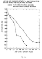
- Fig. 8 and Fig. 9 show the pressure drop curves and the air flow rate of two similar type bag filters, with and without activating the bipolar charge ionizer, respectively. As seen, the bipolar charged filter showed a smaller increase in pressure drop, more dust loading, and higher air flow rate. These distinct advantages are largely the result of electrical deposition.
- the electrical forces change the morphology of particle deposition. Instead of clogging the porosity of the fibrous filter, charged particles deposit on top of each other and develop a chain-like deposition pattern. These "dendrites" extend themselves away from the fiber surface, forming fine irregular shape cylinders, which become very effective collectors themselves and thus greatly enhance the particle collection efficiency of the filter. However, they cause little pressure drop increase because they do not clog the porosity among the fibers as much as when the ionizer is not used.
- Table 1 lists the positive and negative cycle voltage, current, and DOP collection efficiencies up to 10 pounds of powder loading for the bipolar charge filter. Each DOP efficiency shown is an average of three consecutive samples. The cycle times were 30 seconds positive ionization and 60 seconds negative ionization, respectively.
- Table 2 lists the test result for the bag filter without the bipolar charge ionizer. As can be seen, the efficiency was maintained very high throughout the load test for the bipolar charged filter. The pressure drop increased from 0.25 inches of water at the beginning of the loading test to 2.75 inches of water at the end of 10 pounds dust loading. In contrast, the DOP efficiency for the conventional bag filter without the bipolar charge effect was very low at the beginning (41%).
- the ability to run with a very high initial efficiency, maintain at high efficiency and low pressure drop levels throughout a severe loading is the unique advantage of this invention.
- the electrostatic precipitator ESP
Landscapes
- Electrostatic Separation (AREA)
- Filtering Materials (AREA)
- Filtering Of Dispersed Particles In Gases (AREA)
Applications Claiming Priority (2)
| Application Number | Priority Date | Filing Date | Title |
|---|---|---|---|
| US13085793A | 1993-10-04 | 1993-10-04 | |
| US130857 | 1993-10-04 |
Publications (1)
| Publication Number | Publication Date |
|---|---|
| EP0646416A1 true EP0646416A1 (fr) | 1995-04-05 |
Family
ID=22446683
Family Applications (1)
| Application Number | Title | Priority Date | Filing Date |
|---|---|---|---|
| EP94306596A Withdrawn EP0646416A1 (fr) | 1993-10-04 | 1994-09-08 | Filtre chargé bipolairement et méthode pour son utilisation |
Country Status (3)
| Country | Link |
|---|---|
| EP (1) | EP0646416A1 (fr) |
| JP (1) | JPH07246347A (fr) |
| CA (1) | CA2131954A1 (fr) |
Cited By (15)
| Publication number | Priority date | Publication date | Assignee | Title |
|---|---|---|---|---|
| WO1998050162A1 (fr) * | 1997-05-06 | 1998-11-12 | Blue Air Ab | Procede et dispositif d'epuration de fluides gazeux |
| WO2006048509A1 (fr) * | 2004-11-04 | 2006-05-11 | Valtion Teknillinen Tutkimuskeskus | Filtre a particules a haut rendement de retention |
| US7175695B1 (en) | 2005-07-28 | 2007-02-13 | Hess Don H | Apparatus and method for enhancing filtration |
| US7404847B2 (en) | 2005-07-28 | 2008-07-29 | Hess Don H | Apparatus and method for enhancing filtration |
| US20140102295A1 (en) * | 2011-05-24 | 2014-04-17 | Carrier Corporation | Current monitoring in electrically enhanced air filtration system |
| US9028588B2 (en) | 2010-09-15 | 2015-05-12 | Donald H. Hess | Particle guide collector system and associated method |
| US9468935B2 (en) | 2012-08-31 | 2016-10-18 | Donald H. Hess | System for filtering airborne particles |
| CN106334625A (zh) * | 2016-05-19 | 2017-01-18 | 宁波工程学院 | 用于烟道飞灰的双极荷电-磁增强湍流凝并装置和工艺 |
| CN106607188A (zh) * | 2017-01-05 | 2017-05-03 | 宁波工程学院 | 一种用于粉尘颗粒的双极荷电凝并装置 |
| WO2020007549A1 (fr) | 2018-07-03 | 2020-01-09 | Blueair Ab | Purificateur d'air |
| CN111991965A (zh) * | 2020-08-16 | 2020-11-27 | 五邑大学 | 一种长效带电过滤材料及静电过滤除尘器 |
| WO2021078686A1 (fr) | 2019-10-21 | 2021-04-29 | Blueair Ab | Purificateur d'air |
| USD952822S1 (en) | 2020-05-27 | 2022-05-24 | Blueair Ab | Air purifier |
| USD973858S1 (en) | 2020-05-27 | 2022-12-27 | Blueair Ab | Air purifier |
| DE102023120860B3 (de) | 2023-08-07 | 2024-12-19 | Audi Aktiengesellschaft | Verfahren zur Ansteuerung eines Elektroluftfilters für einen Fahrzeuginnenraum eines Kraftfahrzeugs |
Families Citing this family (4)
| Publication number | Priority date | Publication date | Assignee | Title |
|---|---|---|---|---|
| KR100503759B1 (ko) * | 2002-09-17 | 2005-07-26 | 삼성전자주식회사 | 전기집진장치 |
| CN103025434A (zh) * | 2010-06-02 | 2013-04-03 | 三菱重工机电系统株式会社 | 集尘装置的运行方法以及集尘装置 |
| CN106964485B (zh) * | 2017-05-04 | 2018-08-17 | 长江大学 | 一种电气自动化除尘装置 |
| AU2020469631A1 (en) * | 2020-09-23 | 2023-05-11 | Hibocare Technologies South Africa (Pty) Ltd | A panel for an air circulation system |
Citations (4)
| Publication number | Priority date | Publication date | Assignee | Title |
|---|---|---|---|---|
| FR2374939A1 (fr) * | 1976-12-23 | 1978-07-21 | Verto Nv | Procede pour la fabrication d'un filtre en un materiau fibreux electriquement charge d'electrets et filtres a electrets obtenus par ce procede |
| JPS62298465A (ja) * | 1986-06-18 | 1987-12-25 | Hitachi Ltd | 空気清浄機 |
| EP0403230A1 (fr) * | 1989-06-15 | 1990-12-19 | Honeywell Control Systems Ltd. | Epurateur de fluide |
| DE3923640A1 (de) * | 1989-06-15 | 1990-12-20 | Asea Brown Boveri | Verfahren zur ausfilterung von russpartikeln |
-
1994
- 1994-09-08 EP EP94306596A patent/EP0646416A1/fr not_active Withdrawn
- 1994-09-13 CA CA 2131954 patent/CA2131954A1/fr not_active Abandoned
- 1994-10-04 JP JP24026194A patent/JPH07246347A/ja active Pending
Patent Citations (5)
| Publication number | Priority date | Publication date | Assignee | Title |
|---|---|---|---|---|
| FR2374939A1 (fr) * | 1976-12-23 | 1978-07-21 | Verto Nv | Procede pour la fabrication d'un filtre en un materiau fibreux electriquement charge d'electrets et filtres a electrets obtenus par ce procede |
| US4178157A (en) * | 1976-12-23 | 1979-12-11 | N. V. Verto | Method for manufacturing a filter of electrically charged electret fiber material and electret filters obtained according to said method |
| JPS62298465A (ja) * | 1986-06-18 | 1987-12-25 | Hitachi Ltd | 空気清浄機 |
| EP0403230A1 (fr) * | 1989-06-15 | 1990-12-19 | Honeywell Control Systems Ltd. | Epurateur de fluide |
| DE3923640A1 (de) * | 1989-06-15 | 1990-12-20 | Asea Brown Boveri | Verfahren zur ausfilterung von russpartikeln |
Non-Patent Citations (2)
| Title |
|---|
| I.I.INCULET ET AL.: "Conference Record of the 1993 IEEE Industry Applications Conference", 3 October 1993, TORONTO, CA * |
| PATENT ABSTRACTS OF JAPAN vol. 12, no. 198 (C - 502)<3045> 8 June 1988 (1988-06-08) * |
Cited By (21)
| Publication number | Priority date | Publication date | Assignee | Title |
|---|---|---|---|---|
| US6364935B1 (en) | 1997-05-06 | 2002-04-02 | Bleuair Ab | Method and device for cleaning of a gaseous fluid |
| WO1998050162A1 (fr) * | 1997-05-06 | 1998-11-12 | Blue Air Ab | Procede et dispositif d'epuration de fluides gazeux |
| WO2006048509A1 (fr) * | 2004-11-04 | 2006-05-11 | Valtion Teknillinen Tutkimuskeskus | Filtre a particules a haut rendement de retention |
| US7175695B1 (en) | 2005-07-28 | 2007-02-13 | Hess Don H | Apparatus and method for enhancing filtration |
| US7404847B2 (en) | 2005-07-28 | 2008-07-29 | Hess Don H | Apparatus and method for enhancing filtration |
| US7803213B2 (en) * | 2005-07-28 | 2010-09-28 | Hess Don H | Apparatus and method for enhancing filtration |
| US9028588B2 (en) | 2010-09-15 | 2015-05-12 | Donald H. Hess | Particle guide collector system and associated method |
| US20140102295A1 (en) * | 2011-05-24 | 2014-04-17 | Carrier Corporation | Current monitoring in electrically enhanced air filtration system |
| US9797864B2 (en) * | 2011-05-24 | 2017-10-24 | Carrier Corporation | Current monitoring in electrically enhanced air filtration system |
| US9468935B2 (en) | 2012-08-31 | 2016-10-18 | Donald H. Hess | System for filtering airborne particles |
| CN106334625B (zh) * | 2016-05-19 | 2018-04-03 | 宁波工程学院 | 用于烟道飞灰的双极荷电‑磁增强湍流凝并装置 |
| CN106334625A (zh) * | 2016-05-19 | 2017-01-18 | 宁波工程学院 | 用于烟道飞灰的双极荷电-磁增强湍流凝并装置和工艺 |
| CN106607188A (zh) * | 2017-01-05 | 2017-05-03 | 宁波工程学院 | 一种用于粉尘颗粒的双极荷电凝并装置 |
| CN106607188B (zh) * | 2017-01-05 | 2018-02-09 | 宁波工程学院 | 一种用于粉尘颗粒的双极荷电凝并装置 |
| WO2020007549A1 (fr) | 2018-07-03 | 2020-01-09 | Blueair Ab | Purificateur d'air |
| WO2021078686A1 (fr) | 2019-10-21 | 2021-04-29 | Blueair Ab | Purificateur d'air |
| US12455086B2 (en) | 2019-10-21 | 2025-10-28 | Blueair Ab | Air purifier |
| USD952822S1 (en) | 2020-05-27 | 2022-05-24 | Blueair Ab | Air purifier |
| USD973858S1 (en) | 2020-05-27 | 2022-12-27 | Blueair Ab | Air purifier |
| CN111991965A (zh) * | 2020-08-16 | 2020-11-27 | 五邑大学 | 一种长效带电过滤材料及静电过滤除尘器 |
| DE102023120860B3 (de) | 2023-08-07 | 2024-12-19 | Audi Aktiengesellschaft | Verfahren zur Ansteuerung eines Elektroluftfilters für einen Fahrzeuginnenraum eines Kraftfahrzeugs |
Also Published As
| Publication number | Publication date |
|---|---|
| CA2131954A1 (fr) | 1995-04-05 |
| JPH07246347A (ja) | 1995-09-26 |
Similar Documents
| Publication | Publication Date | Title |
|---|---|---|
| EP0646416A1 (fr) | Filtre chargé bipolairement et méthode pour son utilisation | |
| US8080094B2 (en) | Electrically stimulated air filter apparatus | |
| JP2905036B2 (ja) | 静電粒子ろ過装置 | |
| US7914604B2 (en) | Air conditioning system with modular electrically stimulated air filter apparatus | |
| US4357150A (en) | High-efficiency electrostatic air filter device | |
| KR100688945B1 (ko) | 공조기 집진 장치 | |
| US4354858A (en) | Method for filtering particulates | |
| US6790259B2 (en) | Method and device for cleaning a gaseous fluid using a conductive grid between charging head and filter | |
| CA2167054C (fr) | Electrofiltre | |
| US5143524A (en) | Electrostatic particle filtration | |
| US4308036A (en) | Filter apparatus and method for collecting fly ash and fine dust | |
| US3798879A (en) | Air filter with electrostatic particle collection | |
| CA2190954C (fr) | Filtre electrostatique texture | |
| US4976749A (en) | Air filter and particle removal system | |
| US3733784A (en) | Electro-bag dust collector | |
| US6524369B1 (en) | Multi-stage particulate matter collector | |
| US7591884B2 (en) | Air cleaner with electrostatic flocked piles | |
| US4374652A (en) | Filter apparatus and method for collecting fly ash and fine dust | |
| WO1995033570A9 (fr) | Filtre electrostatique texture | |
| WO2002020163A2 (fr) | Filtre a air polarise electronique | |
| EP0403230A1 (fr) | Epurateur de fluide | |
| KR100495627B1 (ko) | 우레탄 필터를 이용한 전기 집진 장치 | |
| WO2010085253A1 (fr) | Système de climatisation avec appareil modulaire de filtration d'air stimulé électriquement | |
| US5711788A (en) | Dust neutralizing and floculating system | |
| Dutta et al. | Hybrid aerosol filtration systems—a review |
Legal Events
| Date | Code | Title | Description |
|---|---|---|---|
| PUAI | Public reference made under article 153(3) epc to a published international application that has entered the european phase |
Free format text: ORIGINAL CODE: 0009012 |
|
| AK | Designated contracting states |
Kind code of ref document: A1 Designated state(s): AT BE CH DE DK ES FR GB IE IT LI NL |
|
| STAA | Information on the status of an ep patent application or granted ep patent |
Free format text: STATUS: THE APPLICATION IS DEEMED TO BE WITHDRAWN |
|
| 18D | Application deemed to be withdrawn |
Effective date: 19951016 |