EP0646528B1 - Dispositif pour envelopper des articles compressibles - Google Patents
Dispositif pour envelopper des articles compressibles Download PDFInfo
- Publication number
- EP0646528B1 EP0646528B1 EP19930307755 EP93307755A EP0646528B1 EP 0646528 B1 EP0646528 B1 EP 0646528B1 EP 19930307755 EP19930307755 EP 19930307755 EP 93307755 A EP93307755 A EP 93307755A EP 0646528 B1 EP0646528 B1 EP 0646528B1
- Authority
- EP
- European Patent Office
- Prior art keywords
- sheet
- packaging
- contents
- article
- elevator
- Prior art date
- Legal status (The legal status is an assumption and is not a legal conclusion. Google has not performed a legal analysis and makes no representation as to the accuracy of the status listed.)
- Expired - Lifetime
Links
- 238000004806 packaging method and process Methods 0.000 claims description 186
- 238000011144 upstream manufacturing Methods 0.000 description 25
- 230000001174 ascending effect Effects 0.000 description 19
- 238000013459 approach Methods 0.000 description 11
- 230000000630 rising effect Effects 0.000 description 7
- 230000006835 compression Effects 0.000 description 5
- 238000007906 compression Methods 0.000 description 5
- 230000007246 mechanism Effects 0.000 description 5
- 238000003825 pressing Methods 0.000 description 4
- 238000007789 sealing Methods 0.000 description 4
- 238000005452 bending Methods 0.000 description 3
- 230000004044 response Effects 0.000 description 3
- 230000009471 action Effects 0.000 description 1
- 230000001419 dependent effect Effects 0.000 description 1
- 238000007599 discharging Methods 0.000 description 1
- 238000006073 displacement reaction Methods 0.000 description 1
- 230000008030 elimination Effects 0.000 description 1
- 238000003379 elimination reaction Methods 0.000 description 1
- 239000004744 fabric Substances 0.000 description 1
- 230000002452 interceptive effect Effects 0.000 description 1
- 238000004519 manufacturing process Methods 0.000 description 1
- 239000012858 resilient material Substances 0.000 description 1
- 230000037303 wrinkles Effects 0.000 description 1
Images




Classifications
-
- B—PERFORMING OPERATIONS; TRANSPORTING
- B65—CONVEYING; PACKING; STORING; HANDLING THIN OR FILAMENTARY MATERIAL
- B65B—MACHINES, APPARATUS OR DEVICES FOR, OR METHODS OF, PACKAGING ARTICLES OR MATERIALS; UNPACKING
- B65B25/00—Packaging other articles presenting special problems
- B65B25/14—Packaging paper or like sheets, envelopes, or newspapers, in flat, folded, or rolled form
-
- B—PERFORMING OPERATIONS; TRANSPORTING
- B65—CONVEYING; PACKING; STORING; HANDLING THIN OR FILAMENTARY MATERIAL
- B65B—MACHINES, APPARATUS OR DEVICES FOR, OR METHODS OF, PACKAGING ARTICLES OR MATERIALS; UNPACKING
- B65B11/00—Wrapping, e.g. partially or wholly enclosing, articles or quantities of material, in strips, sheets or blanks, of flexible material
- B65B11/06—Wrapping articles, or quantities of material, by conveying wrapper and contents in common defined paths
- B65B11/18—Wrapping articles, or quantities of material, by conveying wrapper and contents in common defined paths in two or more straight paths
- B65B11/20—Wrapping articles, or quantities of material, by conveying wrapper and contents in common defined paths in two or more straight paths to fold the wrappers in tubular form about contents
- B65B11/22—Wrapping articles, or quantities of material, by conveying wrapper and contents in common defined paths in two or more straight paths to fold the wrappers in tubular form about contents and then to form closing folds of similar form at opposite ends of the tube
-
- B—PERFORMING OPERATIONS; TRANSPORTING
- B65—CONVEYING; PACKING; STORING; HANDLING THIN OR FILAMENTARY MATERIAL
- B65B—MACHINES, APPARATUS OR DEVICES FOR, OR METHODS OF, PACKAGING ARTICLES OR MATERIALS; UNPACKING
- B65B51/00—Devices for, or methods of, sealing or securing package folds or closures; Devices for gathering or twisting wrappers, or necks of bags
- B65B51/04—Applying separate sealing or securing members, e.g. clips
- B65B51/06—Applying adhesive tape
Definitions
- This invention relates to a wrapping packaging apparatus or device for use in covering substantially rectangular shaped contents with a packaging sheet of craft paper or the like.
- contents comprising piled-up items, for example, piled-up papers, books, clothes, zigzag folded fabrics or accumulated boxes
- contents can be wrapped by being placed above a packaging sheet which in turn is above an elevator, followed by the folding of the packaging sheet in a substantial U-shape so that it lies along the bottom and side surfaces of the contents by descending the elevator.
- both ends of the packaging sheet are folded along the upper surface of the contents and are sealed together.
- a frictional rotating member is abutted against one end of the folded packaging sheet and the frictional rotation member is rotated, thereby one end of the packaging sheet is pushed back in the opposite direction to that in which the contents are moving, and at the same time, the other end of the packaging sheet folded on the upper surface of the contents, is caused to pass below another frictional rotating member, whereby the other end of the packaging sheet is forcibly pushed in the direction of movement of the contents and under the frictional resistance of these two members the packaging sheet is folded, and thereafter an adhering tape is adhered to both ends of the packaging sheet so that the sheet remains wrapped without any looseness.
- an upper flap of each of said ends is folded down along the adjacent side surface of the contents.
- adhering tape fed out by a tape feeding-out mechanism is adhered, by an adhering mechanism, at each side to the overlapped side ends of the packaging sheet, sealing the upper flaps.
- a lower flap at each end is folded along the outer side of the folded upper flap, and the extremity ends of the overlapped lower flaps are folded along the upper surface of the contents by a guide, and finally, adhering tape fed out by the tape feeding-out mechanism is adhered to the extremity ends of the lower flaps and the upper surface of the contents by an adhering mechanism to complete the sealing of the package.
- the entire device is large in its size due to the fact that the packaging start position and the packaging completing position are spaced apart in a vertical direction and in a horizontal direction, and in the case where the contents are positioned at the packaging start position manually, and are lowered from the packaging completing position also manually, the amount of moving around of the worker is high, making the device inconvenient to use.
- an object of the present invention to provide an apparatus or device whereby it is possible to tightly wind the contents by providing that vertical compression can be carried out, and an object of the preferred form of the invention is to provide that the packaging start position and the packaging completing position are as near each other as possible without reducing the packaging speed.
- a packaging apparatus of the type for the wrapping of a substantially rectangular shaped article , wherein a wrapping sheet is positioned above an elevator of the apparatus and the article is positioned above the sheet, and the sheet is folded into U-shape around the bottom surface and the opposing sides of the article by lowering the elevator, sheet and article together in a descending path to a descended position
- the apparatus comprising wrapping guides having inner ends and being mounted for reciprocation towards and away from each other over the upper surface of the article when in the descended position to cause the inner ends to wrap the ends of the sheet over the upper surface of the article and fix them together
- the apparatus includes compressing plates arranged to lie between the wrapping guides and the top surface of the article when in the descended position, said plates being mounted for movement into and out of the descending path so that they can be positioned selectively above the article upper surface, and the elevator can be ascended from the descended position to compress the article against the said plates whilst the ends of the sheet are wrapped by the wrapping guide ends over
- the apparatus include a packaging start position from which the elevator, sheet and article together are descended to the descended position and the wrapping guides form the sheet to tubular form around the article, and a transporting means for horizontally transporting the article and the sheet in tubular form along the mounting surface of the elevator when in the descended position to an intermediate position under a packaging completion position, said elevator being arranged to raise the article and sheet from the intermediate position to the packaging completed position which is adjacent the packaging start position, and further including end folding means for folding each of the ends of the tubular form sheet along the adjacent end of the article as the article advances from the descended position through to the packaging complete position.
- the elevator is adapted to be slightly descended to enable the compressing plates to be moved out of the descending path
- the device may include sheet pressers which are adapted to be moved towards and away from the upper surface of the wrapping guides.
- the compressive receiving plates are positioned above the contents after the elevator is lowered, and thereafter the elevator is ascended to hold the contents against the compressive receiving plates. Thereby, the contents are compressed in a vertical direction.
- the wrapping guides approach each other while the contents are being compressed, and both ends of the packaging sheet are fixed together, and then the compressive receiving plates are pulled out.
- the elevator is slightly descended, the compression of the contents is relaxed, and the compressive receiving plates are moved out of the descending passage.
- the sheet pressers are abutted against the upper surfaces of the wrapping guides after the packaging sheet is folded in a substantial U-shape to hold the ends of the packaging sheet. Thereafter, these wrapping guides are moved to approach to each other along the upper surface of the descended contents, to cause the ends of the packaging sheet to wrapped around and to closely contact the upper and lower surfaces and the inner ends of the wrapping guides, to cause the packaging sheet to be forcibly tensioned around these guides.
- the tension force applied to the packaging sheet is increased due to the frictional resistance between the sheet and the wrapping guides.
- the packaging sheet is in fact pulled out from between the upper surfaces of the wrapping guides and the sheet pressers.
- the packaging sheet may extend from each end of the contents so that as the contents are transported horizontally by the transporting means along the mounting surface of the descended elevator, each of the ends is folded by the folding means and when the contents are ascended and transported by the elevator toward the packaging completing position, they are at the same height position as the packaging start position.
- the leading edge thereof is held which reduces the distance between the packaging start position and the packaging completing position.
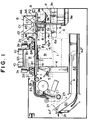
- Fig.1 is a longitudinal front elevational view in section showing one preferred embodiment of the packaging device of the present invention with contents in the packaging start position and also in the packaging completion position.
- Fig.2 is a plan view of the device of Fig.1.
- Fig.3 shows in front view and in sections (a) to (d) the sequence of steps which take place in the feeding out of a packaging sheet from a stack of such sheets.
- Fig.4 shows in front view and in steps (a) to (g) the sequence of steps in the wrapping of the contents with the packaging sheet.
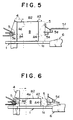
- Fig.5 is an enlarged front view, with a part broken away, to show the position at the start of side flap folding operation.
- Fig.6 is a view similar to Fig. 5, but showing the case when the contents height is smaller.
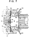
- Fig-7 is an enlarged sectional top plan view showing the position midway of the folding of the side flaps.
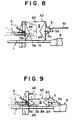
- Fig.8 is a front elevational view, with a part broken away, showing the side flap folding position.
- Fig.9 is a view similar to Fig. 8, but showing the case when the contents height is smaller.
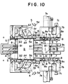
- Fig.10 is an enlarged cross sectional top plan view showing the position just before completion of the folding of the side flaps.
- Fig.11 is a front elevational view, with a part broken away, of Fig.10.
- Fig.12 is view similar to Fig. 11, but showing the case when the contents height is smaller.
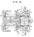
- Fig.13 is an enlarged cross sectional top plan view showing position at the start of the folding down of the upper flap.
- Fig.14 is a front elevational view, with a part broken away, of Fig.13.
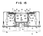
- Fig.15 is a sectional side elevational view, of Fig.13.
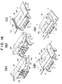
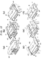
- Fig.16 is a perspective view showing the folding steps in a sequence of steps (a) to (e).
- Fig.17 is a perspective view similar to Fig.16, showing a modified folding operation
- the preferred embodiment is constructed such that a stack of accumulated packaging sheets A are arranged at a lower portion of the device.
- the extremity ends A1 of the accumulated packaging sheets A are slanted upwards as shown. These ends A1 are adapted to be moved together in a bending direction by an adhering means 21 as shown in Fig.3(a). With this movement, the extremity ends A1 are forcibly contacted to adhering tapes C1, C2, C2 fed out from and supported by the tape feeding out means 22, 22, 22.
- the tapes C1,C2,C2 arranged at each of the sealing positions arranged at the centre, right and left of the packaging sheets are applied to the extremity end A1' of the top packaging sheet A which is held by the adhering tapes C1, C2, C2.
- the extremity ends A1 of the remaining packaging sheets A are moved in a counter-bending direction as shown in Fig. 3(b) and become spaced from the top sheet A held by the tapes which are in turn held by the feeding-out mechanisms 22, 22, 22, due to the recovering force of the packaging sheets A as the adhering means 21 is retracted.
- the packaging sheet A held by the adhering tapes C1, C2, C2 is then fed out in a sheet supplying direction toward a packaging start position P1 through a feeding-out passage of inverted L-shape by sheet feeding-out means 23. In this way, the sheets are supplied one-by-one between reference guides 10 and the wrapping guides 2, 2, located at the start position P1.
- the device has an elevator 1 constructed such that the mounting surface 1a on which the bottom surface B4 of the contents B is mounted can reciprocated in a vertical direction along an ascending and descending passage 1b.
- the width of the mounting surface 1a in the sheet supplying direction is such that two contents B of the maximum size can be arranged side-by-side in the sheet supplying direction, and the horizontal length of the mounting surface at a right angle to the sheet supplying direction is such that, in relation to the sheet supplying direction, said length is shorter at the downstream side than at the upstream side, and is substantially the same or shorter than the length size of the contents B of the minimum size.
- the surface 1a has arms 1c, 1c projecting to the right and left and arranged at a lower level as shown in Fig. 15
- Suspending receiving tables 1d, 1d are vertically arranged in relation to the arms 1c, 1c in such a way that the tables may be reciprocated to the right and left.
- the upper surfaces of these tables 1d, 1d are arranged at the same height as the mounting surface 1a, and are cooperatively related to the supporting frames 7b, 7b of the folding guides 7, 7. This cooperation may be for example, by connecting pieces 1e, 1e.
- the upper surfaces of the suspending receiving tables 1d, 1d are near the right and left ends of the bottom surface B4 of the contents B dependent upon the variation in the length size of the contents B.
- a driving part such as a stepping motor, for example, is cooperatively arranged in relation to these arms 1c, 1c and the mounting surface 1a so that the arms and the mounting surface are ascended or descended by the driving part.
- the driving part for the elevator 1 is controlled in its operation by a control part not shown, so that the mounting surface 1a is ascended to its upper limit position (the initial state) just after the packaging sheet A is supplied, and it approaches the wrapping guides 2, 2.
- the contents B is placed on the packaging sheet A and the sheet pressers 2d are moved away horn the upper surfaces 2a, 2a of the wrapping guides 2, 2.
- the upper surface B3 of the contents B is lowered down to the lower limit position below the wrapping guides 2, 2 and the compressive receiving plates 3, 3, and subsequently the elevator is ascended a slight amount, once or a plurality of times until the upper surface B3 of the contents B is forcibly contacts the compressive receiving plates 3, 3. It is slightly lowered after the downstream end wrapping guide 2 is projected to a central tipper positions of the compressive receiving plates 3, 3.
- the lateral folding guides 5 ascend or descend regardless of the height size of the contents B in such a way that the guides are opposite the desired height positions of both side flaps A4, and upon completion of the advancing movement of the pusher 6, the next packaging sheet A is supplied to the packaging start position P1 and the elevator is ascended up to its upper limit position and returned to its initial state.
- the wrapping guides 2, 2 are constructed such that their upper surfaces 2a, 2a are substantially horizontal and opposing ends 2b, 2b are parallel with side surfaces B1, B1 of the descended contents B and in the right and left direction are longer than the length size of the contents B of the maximum size.
- the resilient members 2c, 2c may be sponges or leaf springs, and are fixed to the lower surfaces of the guides 2, 2.
- the guides 2, 2 are arranged in such a manner that they may be reciprocated in the vertical direction and in the sheet supplying direction along the upper surface B3 of the descended contents B.
- a driving part such a stepping motor, for example, is cooperatively arranged in relation to each guide, and they may be moved up and down and alternatively reciprocated by this driving part.
- the driving part for the wrapping guides 2, 2 is controlled in its operation by the control part in the same manner as that for the driving part for the elevator 1.
- the inner ends 2b, 2b are held in the substantial same vertical plane as both side surfaces B1, B1 of the contents B and are slightly moved upwardly as the elevator 1 ascended up to its upper limit position (the initial state). Said inner ends 2b, 2b are moved by a predetermined amount in a direction approaching each other just after the elevator 1 is descended down to its lower limit position.
- the wrapping guide 2 arranged at upstream side in the sheet supplying direction is moved by the desired amount just after the elevator 1 is slightly ascended to press the contents B to the compressive receiving plates 3, 3.
- the wrapping guide 2 arranged at the downstream side is moved by a predetermined amount, once or a plurality of times.
- the wrapping guide 2 at the upstream end is moved to the central upper position in relation to the compressive receiving plates 3, 3.
- the wrapping guide 2 at the upstream side is moved in the opposite direction, and concurrent with this operation, the wrapping guide 2 at the downstream end is moved to the central upper position in relation to the compressive receiving plates 3, 3.
- the wrapping guides 2, 2 are moved horizontally toward the downstream side concurrent with the supply of the next packaging sheet A to the packaging start position P1, and upon completion of supply of the next packaging sheet A, each of the wrapping guides 2, 2 is returned by being moved horizontally and at the same time moved slightly upwardly, as the elevator 1 is ascended, whereby they are returned to their initial state.
- the upper surfaces 2a, 2a of the wrapping guides 2, 2 are provided with sheet pressers 2d comprising for example weights, which may be moved toward or away from the guides in the vertical direction.
- sheet pressers 2d are arranged so as not to interfere with the passing of the adhering tape C1 adhered to the packaging sheet A.
- driving parts 2e, 2e such as for example solenoids arranged above them.
- the sheet pressers 2d are moved up and down by these driving parts 2e, 2e and moved toward and away from the upper surfaces 2a, 2a of the wrapping guides 2, 2.
- the driving parts 2e, 2e for the sheet pressers 2d are controlled in their operations by a control part so that the sheet pressers 2d are moved and press contacted with the upper surfaces 2a, 2a of the wrapping guides 2, 2 when in the initial state, after supply of the packaging sheet A.
- the sheet pressers 2d are moved upwardly when the packaging start switch S2 is operated, to move away from the wrapping guides 2, 2.
- the sheet pressers 2d are moved downwardly just after the elevator 1 is descended down to its lower limit position, to press contact the upper surfaces 2a, 2a of the wrapping guides 2, 2.
- the sheet pressers 2d are moved upwardly upon completion of the approaching of wrapping guides 2, 2, and then the sheet pressers 2d are moved downwardly after the next packaging sheet A is supplied to the packaging start position P1 and the guides 2, 2 have returned to the intial state.
- the compressive receiving plates 3, 3 are arranged reciprocably in such a manner that they are movable in the right and left direction from a position outside the ascending or descending passage 1b of the elevator 1 to a position in the ascending or descending passage 1b and between the wrapping guides 2, 2 and the upper surface B3 of the descended contents B.
- Their width size in the sheet supplying direction when projected into the ascending or descending passage 1b is the same as the width size of the contents B in the sheet supplying direction so that the side ends of the plates 3, 3 in the sheet supplying direction are arranged just above the ends of the upper surface B3 of the contents B.
- a driving part such as a stepping motor, for example, is cooperatively arranged with these compressive receiving plates 3, 3 to move them in the right and left direction.
- the driving part for the compressive receiving plates 3, 3 is controlled in its operations by a control part so that the compressive receiving plates 3, 3 are held out of the ascending or descending passage 1b of the elevator 1 so as not to interfere with the descending of the packaging sheet A and the contents B by the elevator 1.
- the plates 3, 3 are engaged with the right and left ends of the upper surface B3 of the contents B, and after the elevator 1 is slightly descended, they are returned to their initial states by being moved out of the ascending or descending passage 1b of the elevator 1 from above the contents B.
- each of the compressive receiving plates 3 is divided into two segments 3a, 3b spaced in the sheet supplying direction and arranged to overlap in the vertical direction.
- the plate segments have base ends positioned outside the path 1b and are cooperatively related to a rotary driving part such as a stepping motor, for example, and are rotatably supported for movement in a horizontal direction.
- a rotary driving part such as a stepping motor, for example
- the divided plate segments 3a, 3b are overlapped in the held state and are rotated around pivots at the base ends by 90 degrees from this state toward the ascending or descending passage 1b of the elevator 1, whereby the extremity ends of the divided segments 3a, 3b are projected in a substantial horizontal direction into the passage 1b.
- This arrangement results in that the compressive receiving plates 3, 3 are compact in the right and left direction.
- the transporting means 4 for horizontally transporting the descended contents B in the sheet supplying direction along the mounting surface 1a of the descended elevator 1 towards a packaging completing position P2.
- Packaging completion position P2 is arranged adjacent the packaging start position P1.
- an end folding means which folds each of the extending ends A3, A3 of the wrapped packaging sheet A along the opened side surface B2, B2 of the contents B. This folding takes place during the time from start of the horizontal transportation of the contents B by the transporting means 4 to the ending of the ascending transportation of the contents B to the packaging completing position P2 by the elevator 1.
- the transporting means 4 passes vertically through the mounting surface 1a of the elevator 1 and is arranged in the sheet supplying direction in such a manner that it may be reciprocated.
- the upper end of the vertical transferring surface 4a is arranged below the compressive receiving plates 3, 3 and at the same time a driving part such as a stepping motor, for example, is arranged to reciprocate the transporting surface 4a.
- the driving part for the transporting means 4 is controlled in its operation by a control part such that the transporting surface 4a is held on the upstream vertical surface B1 of the contents B, and advancing movement of the transporting surface 4a is started substantially concurrent with the advancing movement of upstream side lateral folding guides 5, 5.
- the transporting surface is stopped at the position where the downstream side surface B1 of the contents B is abutted against abutting portions 5a, 5a of downstream side lateral folding guides 5, 5.
- the upstream side lateral folding guides 5, 5 advance up to desired positions in relation to the opened side surfaces B2, B2 of the contents B and then the transporting surface 4a is advanced again at the same speed. It is stopped when it has advanced to a predetermined position in relation to the downstream side lateral folding guides 5, 5. It is retracted to its initial state toward the upstream side when the elevator 1 is midway in its ascending operation, or just after completion of the ascending operation.
- the folding means 5, 5 is constructed such that the lateral folding guides 5 abutting against both side flaps A4 of the extending ends A3, A3 during the horizontal transportation of the contents B by the transporting means 4, causing folding of each of the side flaps along the opened side surfaces B2, B2 of the contents B.
- the upper folding guides 6, 6 abut against the lower flaps A5, A5 and folding them up along the opened side surfaces B2, B2 of the contents B.
- Folding means 5 and guides 6 are arranged in sequence, and folding guides 7, 7 are arranged above the upper folding guides 6, 6 and are opposite guides 6, while guides 6 are being abutted against each of the opened side surfaces B2, B2 of the contents B.
- Guides 7 are arranged in such a manner that they may be projected out along the bottom surface B4 or the upper surface B3 of the contents B.
- each of the lateral guides has portions rotatably supported in the folding directions of the side flaps A4 and comprising abutting portions 5a which in their initial states oppose and are spaced apart form the closed side surfaces B1, B1 of the contents B, and folding portions 5b arranged to be folded from the initial state against the side flaps A4.
- these lateral folding guides 5 descend the folding portions 5b by a predetermined amount toward the lower flaps A5, A5 as each of the portions 5a, 5a is rotated by 1/4 of a rotation, at the same time rubbing the four comers of side surfaces B1, B1, B2, B2 of the contents B.
- the elevator 1 and the upper folding guides 6, 6 are descended upon completion of the wrapping stage by the predetermined amount corresponding substantially to the amount by which of each of the folding portions 5b is descended, and in turn in the case that the extending length of each of the extending ends A3 is shorter than a half of the width size of each of the side surfaces B2, the elevator 1 and the upper folding guides 6, 6 are ascended by the predetermined amount in such a manner that the lower ends of the descended folding portions 5b coincide with the bottom surface B4 of the contents B.
- the upstream side lateral folding guides 5, 5 are cooperatively provided with driving parts such as stepping motors, for example. These driving parts are controlled in their operations by a control part such that the abutting portions 5a, 5a and the folding portions 5b, 5b are held at positions not interfering with the descending operation of the packaging sheet A and the contents B.
- driving parts are controlled in their operations by a control part such that the abutting portions 5a, 5a and the folding portions 5b, 5b are held at positions not interfering with the descending operation of the packaging sheet A and the contents B.
- the upstream abutting portions 5a, 5a are moved in the same direction substantially concurrent with the advancing movement of the transporting means 4 until they are abutted against the closed upstream side surface B1 of the contents B to cause the folding portions 5b, 5b to be rotated.
- the downstream side lateral folding guides 5, 5 are held by temporary holding portions 5d, 5d such as permanent magnets or electromagnets, for example, so that the abutting portions 5a, 5a are held substantial parallel to the closed downstream side surface B1 of the contents B.
- Inclined cam surfaces 5e, 5e are formed at the lower ends of the abutting portions 5b, 5b which are rotated in the folding direction as the side flaps A4, A4 are folded, and the upper inclined sides 6a, 6a of the ascending upper folding guides 6, 6 subsequently engaged these cam surfaces 5e, 5e, whereby the downstream lateral folding guides 5, 5 are forcibly rotated in a reverse direction to be returned to their initial states.
- the upper folding guides 6, 6 are vertically arranged in the same horizontal plane as the opened side surfaces B2, B2 of the wrapped contents B. They lie at the downstream end of the downstream side lateral folding guides 5, 5, and have upper inclined sides 6a, 6a which engage the lower flaps A5, A5.
- the guides 6, 6 are supported to be movable in a vertical direction, whereby the upper inclined sides 6a, 6a can be adjusted and moved to lie slightly higher than the mounting surface 1a during its descending operation regardless of the amount the elevator 1 descends.
- the folding guides 7, 7 are constructed such that supporting flames 7b, 7b are arranged above the upper folding guides 6, 6 and they may be adjusted and moved in the right and left direction depending upon variation of the length size of the contents B.
- Each of the inner ends 7a, 7a is supported by these supporting flames 7b, 7b in such a manner that it may be reciprocated in the right and left direction to move them away from each other.
- Weights 7c, 7c are for applying a specified pressure in the direction for causing the inner ends 7a, 7a to approach each other, but stoppers 7d, 7d make it impossible for the inner ends 7a, 7a, to abut against the upper surface B3 of the contents B as they ascend with the elevator 1.
- Recovering means 7e, 7e serve to move the projected inner ends 7a, 7a in the reverse direction.
- the weights 7c, 7c are cooperatively related to the inner ends 7a, 7a by means such as a wire, for example, the wire passing round freely rotatable roller on the supporting flames 7b, 7b so that the inner ends 7a, 7a are always pressed by the weights in the direction in which they approach each other.
- a wire for example, the wire passing round freely rotatable roller on the supporting flames 7b, 7b so that the inner ends 7a, 7a are always pressed by the weights in the direction in which they approach each other.
- the stoppers 7d, 7d can be moved in the vertical direction to move toward and away from the inner ends 7a, 7a. They are always pressed in a direction to abut against the inner ends 7a, 7a by a resilient member such as a spring, for example. The right and left ends of the upper surface B3 of the ascending contents B are abut against the stoppers and they are moved in a releasing direction away from the inner ends 7a, 7a.
- the recovering means 7e, 7e are cooperatively related to the arms 1c, 1c, which project in the right and left direction from the lower part of the elevator 1, by means of resilient material such as a spring or wire. After the elevator 1 is descended from the upper limit position to the predetermined height position, the inner ends 7a, 7a are moved away from each other and back to their initial states.
- the supporting means comprising latches 8 resiliently project along the bottom surface B4 of the contents B when ascended by the elevator 1.
- the latches are arranged near the folding guides 7, 7, and project by a small amount to the left and right from the supporting frames 7b, 7b of the folding guides 7, 7.
- the latches are urged by resilient members 8a such as springs, for example.
- a latch 9 which projects by a large amount is fed into or fed out of a recess 1f formed at the downstream end of the mounting surface 1a of the elevator 1.
- Latch 9 projects toward the substantial central part of the bottom surface B4.
- the upper end surfaces of these latches 8, 9 are arranged at substantially the same height position as that of the upper surfaces of the folding guides 7, 7 for the support of the bottom surface B4 of the contents B when the latches are in their projected conditions.
- the latch 9 is constructed such that a rising piece 9b thereof is reciprocably fed in a sheet supplying direction on a base table 9a disposed below the lower limit position of the mounting surface 1a, and the rising piece 9b is always pressed toward the upstream side by a resilient member 9c such as a spring, for example, disposed between the rising piece 9b and the flame F.
- reference guides 10 are arranged to be spaced apart above the elevator 1, and when the contents B is placed at the packaging start position P1 it is enclosed by these members so that side surfaces B1, B1, B2, B2 of the contents B are abutted against each of the reference guides 10 Thereby the contents B are position set, and at the same time, a sheet guide 11 for bending upwardly and holding the extremity end A1 of the packaging sheet A is arranged between the packaging start position P1 and the packaging completing position P2.
- an inputting means 12 for example, for inputting an outer shape and an outer size of the packaging sheet A and the contents B, a sheet feeding-out start switch S1 and the packaging start switch S2.
- the inputting means 12 is communicated with the aforesaid sheet feeding-out means 23 through the control part, and the inputting means is operated every time the size of the outer shape and size of the packaging sheet A and the contents B are changed.
- the driving part for the sheet feeding-out means 23 is controlled in its operation in response to the calculation at the control part, whereby the extremity end A1' of the packaging sheet A is wrapped and overlapped regardless of the variation in size so as to disposed at the central position in the sheet supplying direction of the upper surface B3 of the contents B.
- the feeding-out amount of the packaging sheet is adjusted in such a manner that wrapping completion form becomes constant and at the same time the inputted value is displayed by a displaying part 12a such as a CRT, for example.
- the sheet feeding-out start switch S1 and the packaging start switch S2 are communicated with the driving part for the aforesaid tape feeding-out means 22, 22, 22, the driving part for the adhering means 21, the driving part for the sheet feeding-out means 23, the driving part for the elevator 1, the driving part for the wrapping guides 2, 2, the driving part for the compressive receiving plates 3, 3, the driving part for the transporting means 4, the driving part for the lateral folding guides 5, and the driving part for the upper folding guides 5, 6 through the control part.
- the driving part for the tape feeding out means 22, 22, 22, 22, the driving part for the adhering means 21, and the driving part for the sheet feeding-out means 23 are operated in sequence and one packaging sheet A is supplied to the packaging start position P1.
- the contents B are placed at the packaging start position P1.
- the packaging start switch S2 is manually operated, and the driving part for the elevator 1, the driving part for the wrapping guides 2, 2, the driving part for the compressive receiving plates 3, 3, the driving part for the transporting means 4, the driving part for the lateral folding guides 5, and the driving part for the upper folding guides 6, 6 are operated in sequence and packaging of the contents B is started.
- the driving part for the tape feeding-out means 22, 22, 22, the driving part for the adhering means 21, and the driving part for the sheet feeding-out means 23 are operated in sequence, and the next packaging sheet A is supplied to the packaging start position P1.
- the sheet supplying start switch S1 is manually operated to cause one packaging sheet A having the adhering tapes C1, C2, C2,to be supplied to the packaging start position P1 along the feeding-out passage A1. Its extremity end A1 is bent upwardly along the guide 11 as shown in Fig. 1 and is held there. In the case that the packaging sheet A is long, its terminal end portion A2 is bent downwardly along the feeding-out passage A1 and held there.
- the sheet pressers 2d Upon completion of transportation of the packaging sheet A, the sheet pressers 2d are moved downwardly to hold the packaging sheet A supplied between the upper surfaces 2a, 2a of the wrapping guides 2, 2 as shown in Fig.1. Positional displacement of the packaging sheet A is prevented, and under this condition, the contents B are position set on the packaging sheet A, and the packaging sheet A is bent due to the weight of the contents B and the lower surface B4 of the contents B is abutted against the mounting surface 1a of the elevator
- the sheet pressers 2d are moved upwardly, so that the holding of the packaging sheet A is released, and the elevator 1 starts to descend. Thereby, the packaging sheet A is bent into a substantial U-shape along the bottom surface B4 and both side surfaces B1, B1 of the contents B, as shown in Fig.4 (a).
- the sheet pressers 2d are moved downwardly to hold the packaging sheet A between the upper surfaces 1a, 1a of the wrapping guides 2, 2. Concurrent with this holding operation, the compressive receiving plates 3, 3 are moved to a position above the contents B.
- the elevator 1 is slightly ascended as shown in Fig.4(b), so that the upper surface B3 of the contents B is engaged with the compressive receiving plates 3, 3 and at the same time the contents B is immovably held between the mounting surface 1a and the compressive receiving plates 3, 3.
- the contents B are compressed in a vertical direction, and the portions of the packaging sheet opposite the side surfaces B1, B1 of the contents B are loosened in the vertical direction.
- the upstream side wrapping guide 2 is moved to the position as shown in Fig.4(c) and subsequently the downstream side wrapping guide 2 is moved to the position as shown in Fig.4(d).
- each of the extremity end A1 and the terminal end A2 of the packaging sheet is wrapped and closely contacted in a U-shape along the upper surfaces 2a, 2a, the inner ends 2b, 2b of the wrapping guides 2, 2 and the resilient members 2c, 2c.
- the loosened portions of the packaging sheet A are, due to frictional resistance between the wrapping guides 2, 2 and the sheet, pulled upwardly and tensioned as shown in Fig. 4(d). Thereafter, with a slight ascending of the elevator 1 and repetition of the projection of the wrapping guides 2, 2, the contents B are further metered in the vertical direction and the packaging sheet is fastened.
- the tension force applied to the packaging sheet A is increased due to the frictional resistance between the packaging sheet A and the wrapping guides 2, 2, so that each of the packaging sheets A is pulled out from between the upper surfaces 2a, 2a of the wrapping guides 2, 2 and the sheet pressers 2d.
- the terminal end A2 of the packaging sheet A is bent in advance along the upper surface B3 of the contents B as shown in Fig.4(c).
- the extremity end A1 of the packaging sheet A is also pulled out as shown in Fig.4(d), and at this time, an adhering surface of the adhering tape C1 is adhered to the bottom surface of the sheet pressers 2d to cause the pulling-out of the extremity end A1' to be stopped.
- the packaging sheet A is further fastened.
- the sheet is bent along the upper surface B3 of the contents B and concurrent with this operation, the bent end A2' and the extremity end A1' are pushed against the upper surface B3 of the contents B by the resilient members 2c, 2c and a removal of each of the ends is prevented.
- the sheet pressers 2d are moved upwardly as shown in Fig.4(e), the downstream side wrapping guide 2 is projected to the central upper position of the compressive receiving plates 3, 3 as shown in Fig.4(f) whereby the extremity end A1, of the packaging sheet A is overlapped with the terminal end A2.
- the overlapped terminal end A2' and the extremity end A1' are held by the resilient member 2c at the lower surface of the downstream side wrapping guide 2 and the upper surface B3 of the contents B, and the projecting portions of the adhering tapes C1, C2, C2 adhered to the extremity end A1' are pushed against the terminal end A2'.
- the adhering tapes C1, C2, C2 are adhered to both sheet ends and seal same.
- the elevator 1 is slightly descended as shown in Fig.4(g) to loosen the compression of the contents B. Thereafter, the compressive receiving plates 3, 3 are pulled out to complete the wrapping stage.
- the contents B is descended by a predetermined height by the elevator 1, as shown in Fig.5, and in the case that the length of each of the extending ends A3 is shorter than a half of the width size of each of the opened side surfaces B2, the contents B is ascended by the predetermined height by the elevator 1 as shown in Fig. 6.
- the contents B are transported by the advancing movement of the transporting means 4.
- the closed downstream side surface B1 of the contents B is abutted against the abutting portions 5a, 5a of the downstream side lateral folding guides 5, 5 as shown in Fig.7, and at this time, the contents B are removably held between the temporary stopped transporting means 4 and the downstream side abutting portions 5a, 5a temporarily held by the temporary holding portions 5d, 5d.
- each of the inner surface intermediate portions is rotated by 1/4 rotation while rubbing the comers between the upstream side surface B1 and the side surfaces B2, B2.
- the entire upstream side flaps A4, A4 are pulled downwardly and are tightly bent along the opened side surfaces B1, B2 of the contents B, while the base end upper portions of these side flaps A4, A4 are being press contacted to the comers.
- each of the extending ends A3 is longer than half of the width of each of the open side surfaces B2
- the contents B are descended by an amount corresponding to the amount which the folding portions 5b, 5b descend before their folding operations, so that the folding portions 5b, 5b are abutted against vertical intermediate positions of the folded side flaps A4 as shown by the double dotted lines in Fig.8.
- the contents B are ascended by a predetermined height before folding of the upstream side flaps A4, A4, so that the lower ends of folding portions 5b, 5b are descended to the bottom surface B4 of the contents B as shown by the double dotted lines in Fig.9.
- the contents B are transported again by the transporting means 4, and the folding portions 5b, 5b are descended toward the lower flaps A5, A5 as the intermediate portions of the downstream side lateral folding sides 5, 5 are rotated by 1/4 rotation.
- the guides rub the comers between the downstream side surface B1. and the open side surfaces B2, B2. Thereby the entire downstream side flaps A4, A4 are pulled downwardly, and the base end of the upper portions of these side flaps A4, A4 are tightly folded and press contacted to the comers.
- each of the extending ends A3 is longer than half of the width of the open side surfaces B2
- the contents B are transported while the upstream side lateral folding guides 5, 5 are stopped at the folding position.
- the vertical intermediate extremity ends of the downstream side flaps A4, A4 are overlapped on the outside of the vertical intermediate extremity end of the folded upstream side flaps A4, A4 as shown in Fig.11, and concurrent with this operation, and the folding of both side ends of the lower flaps A5, A5 and the upper flaps A6, A6 is stopped in a midway position, so that each of them becomes of horizontally projected, trapezoidal form.
- each of the extending ends A3 is shorter than half of the width of each of the open side surfaces B2
- the lower ends of the folding portions 5b, 5b descend down to the bottom surface B4 of the contents B as shown in Fig.12, and folding is applied to the downstream end portions of the lower flaps A5, A5 by the transportation of the contents B by the transporting means 4 to reach the position as shown in Fig. 16(a).
- the contents B pass between the inner surfaces of the abutted and rotated lateral folding guides 5, whereby the contents B are guided to the downstream side on to the upper surfaces of suspending receiving tables 1d, 1d which abut the contents B near the right and left ends of the bottom surface B4 of the contents B.
- the portions near the right and left ends of the bottom surface B4 are prevented from being unsupported, and concurrent with this operation, the base ends of the lower flaps A5, A5 are engaged by the upward inclined sides 6a, 6a of the upper folding guides 6, 6 and are folded up. Thereby, the folded-up side flaps A4 are prevented from becoming loose.
- the closed downstream side surface B1 of the contents B is abutted against the rising piece 9b of the latch 9 as shown by a chain dotted line in Fig.1. It is transported to the downstream end and the rising piece 9b is pressed against the closed downstream side surface B1 until the contents B reaches the predetermined position, and then the advancing movement of the transporting means 4 ends.
- the upstream side lateral folding guides 5, 5 are engaged with the returning projections 5c, 5c as shown in Fig.13, and thereby the upstream side lateral folding guides 5, 5 are forcibly reversibly rotated and returned to their initial states.
- the upper folding guides 6, 6 ascend to fold up the lower flaps A5, A5 onto the outside of the side flaps A4, A4 as shown in Fig.16(b).
- the lower flaps A5, A5 are folded up onto the outside of the side flaps A4 while pressing rods 5f, 5f maintain the folded state, and at the same time, upper inclined sides 6a, 6a engage the inclined cam surfaces 5e, 5e of the downstream side lateral folding guides 5, 5.
- the downstream side lateral folding guides 5, 5 are forcibly reverse rotated as shown in Fig. 13 and returned to their initial states.
- the mounting surface 1a of the elevator 1 and the suspending receiving tables 1d, 1d ascend to push up the contents B while engaged by the advanced and stopped pushing surface 4a, the rising piece 9b of the latch 9 and the ascended upper folding guides 6, 6.
- the upper surface B3 of the ascending contents B abuts against the stoppers 7d, 7d of the folding guides 7, 7, the inner ends 7a, 7a of the folding guides 7, 7 are pushed by the weights 7c, 7c at a specified pressure against the open side surfaces B2, B2 of the contents B as shown Fig. 16(d).
- the upper flaps A6, A6 are gradually folded down, with a rubbing action, as shown in Fig. 16(d) and are overlapped on the outside of the lower flaps A5, A5.
- adhering tapes C2, C2 are adhered to the extremity ends of the upper flaps A6, A6 and said ends are tensioned downwardly by the inner ends 7a, 7a of the folding guides 7, 7, and the tapes are adhered to the lower flaps A5, A5, completing the folding stage.
- the extremity ends of the upper flaps A6, A6 are projected along the bottom surface B4 of the contents B in that upon completion of the folding-down operation, the inner ends 7a, 7a of the folding guides 7, 7 are projected along the bottom surface B4 of the contents B by the weights 7c, 7c when the ascending contents B pass between the inner ends 7a, 7a of the folding guides 7, 7, as shown in Fig. 16(e).
- the raised contents B are supported by latches 8 which project along the right and left ends of the bottom surface B4 and the rising piece 9b of the latch 9 which projects up to near the central part of the bottom surface B4.
- the completely wrapped contents B remains supported by the latches 8, 9 even if the next contents B are placed to start the packaging operation.
- the elevator 1 starts to descend and the folding guides 7, 7 are moved in a direction moving away from each other, resulting in that the wrapped contents B do not descend.
- the wrapped contents B remain supported on the latches 8.
- control part automatically changes the feeding of the packaging sheet A by the sheet feeding-out means 23 in response to inputted size data.
- the control part automatically changes the feeding-out of the packaging sheet A by the sheet feeding-out means 23, automatically changes the descending amount of the elevator 1 and the height positions of the upper folding guides 6, 6.
- the control part automatically changes the feeding-out of the packaging sheet A by the sheet feeding-out means 23, the control part moves each of the reference guides 10, wrapping guides 2, 2 in the sheet supplying direction, automatically changes the spacings, and when the length size of the contents B is changed, the control part moves each of the upper folding guides 6, 6, the folding guides 7, 7 in the right and left direction and automatically changes the spacings.
- one sheet of the accumulated packaging sheets A is separated and supplied onto the elevator 1.
- the invention is not limited to this operation.
- a rolled up packaging sheet may be cut to a predetermined length and it may be supplied to the elevator 1.
- the upper flaps A6, A6 are folded by ascending the contents B with the elevator 1 to overlap the outside of the lower flaps A5, A5.
- the present invention is not limited to this operation.
- the upper flaps A6, A6 are folded down by the folding-down guides 13, 13 arranged between the downstream side lateral folding guides 5, 5 and the upper folding guides 6, 6, the lower flaps A5, A5 are folded up by the upper folding guides 6, 6 and overlapped on the upper flaps A6, A6.
- the extremity ends of these lower flaps A5, A5 may be folded along the upper surface B3 of the contents B and sealed by the sealing tapes, by the projecting movement of the folding guides 7, 7.
Landscapes
- Engineering & Computer Science (AREA)
- Mechanical Engineering (AREA)
- Basic Packing Technique (AREA)
Claims (5)
- Un équipement de conditionnement du type destiné à emballer un article de forme essentiellement rectangulaire (B), dans lequel une feuille d'emballage est positionnée au-dessus d'un élévateur (1) de l'équipement et l'article (B) est positionné au-dessus de la feuille (A), et la feuille (A) est pliée en forme d'U autour de la face inférieure (B4) et des côtés opposés (B1, B1) de l'article (B) en faisant descendre ensemble l'élévateur (1), la feuille (A) et l'article (B) selon un parcours descendant vers une position abaissée, l'équipement comprenant des guides d'enrobage (2) possédant des extrémités internes (2b) et étant montés en vue d'un mouvement de va-et-vient pour se rapprocher et s'éloigner l'un de l'autre au-dessus de la surface de l'article (B) quand celui-ci se trouve en position abaissée, afin d'obliger les extrémités internes (2a) à placer les extrémités de la feuille au-dessus de la face supérieure de l'article, afin d'envelopper cette dernière, et à les fixer ensemble, caractérisé en ce que l'équipement comprend des plaques de compression (3) agencées de façon à se trouver entre les guides d'enrobage (2) et la face supérieure (B3) de l'article (A), quand celui-ci se trouve en position abaissée, lesdites plaques (3) étant montées de façon à pouvoir se déplacer dans le parcours de descente, et à pouvoir en sortir, pour qu'il soit possible de les positionner de manière sélective au-dessus de la face supérieure (B3) de l'article, et l'élévateur (1) peut remonter de sa position abaissée afin de comprimer l'article (B) contre lesdites plaques (3), pendant que les extrémités de la feuille (A) sont placées par les extrémités des guides d'enrobage (2a) au-dessus de l'article (B) afin d'envelopper ce dernier, et de fixer les extrémités ensemble.
- Un équipement de conditionnement, selon les stipulations de la revendication 1, dans lequel l'élévateur (1) est adapté de façon à se trouver en position légèrement abaissée pour permettre aux plaques de compression (3) de se déplacer pour sortir du parcours de descente.
- Un équipement de conditionnement, selon les stipulations de la revendication 1, comportant des systèmes de pression de feuilles (2d) agencés pour avoir un mouvement de va-et-vient leur permettant d'être rapprochés et éloignés de la face supérieure des guides d'enrobage (2).
- Un équipement, selon les stipulations de la revendication 1, comprenant une position de début du conditionnement (P1) à partir de laquelle l'élévateur (1), la feuille (A) et l'article (B) descendent ensemble vers la position abaissée, et les guides d'enrobage (2) façonnent la feuille (A) en une forme tubulaire autour de l'article (B), et comprenant un moyen de transport (4) destiné à acheminer dans un plan horizontal l'article (B) et la feuille (A) en forme tubulaire, le long de la surface de montage (1a) de l'élévateur (1) quand celui-ci se trouve en position abaissée, jusqu'à une position intermédiaire située en dessous d'une position d'achèvement du conditionnement (P2), ledit élévateur (1) étant agencé de manière à relever l'article (B) et la feuille (A) à partir de la position intermédiaire jusqu'à la position d'achèvement du conditionnement (P2), qui est adjacente à la position de début du conditionnement (P1), et comprenant en outre un moyen de pliage des extrémités (5, 6, 7) destiné à plier chacune des extrémités de la feuille en forme tubulaire (A) le long du côté adjacent de l'article (B), au fur et à mesure que l'article progresse de la position abaissée jusqu'à la position d'achèvement du conditionnement (P2).
- Un équipement, selon les stipulations de la revendication 4, dans lequel on a prévu un passage de guidage (A1) entre la position de début du conditionnement (P1) et la position d'achèvement du conditionnement (P2).
Priority Applications (2)
| Application Number | Priority Date | Filing Date | Title |
|---|---|---|---|
| EP19930307755 EP0646528B1 (fr) | 1993-09-30 | 1993-09-30 | Dispositif pour envelopper des articles compressibles |
| DE1993617565 DE69317565T2 (de) | 1993-09-30 | 1993-09-30 | Vorrichtung zum Umhüllen von zusammendrückbaren Gegenständen |
Applications Claiming Priority (1)
| Application Number | Priority Date | Filing Date | Title |
|---|---|---|---|
| EP19930307755 EP0646528B1 (fr) | 1993-09-30 | 1993-09-30 | Dispositif pour envelopper des articles compressibles |
Publications (2)
| Publication Number | Publication Date |
|---|---|
| EP0646528A1 EP0646528A1 (fr) | 1995-04-05 |
| EP0646528B1 true EP0646528B1 (fr) | 1998-03-18 |
Family
ID=8214563
Family Applications (1)
| Application Number | Title | Priority Date | Filing Date |
|---|---|---|---|
| EP19930307755 Expired - Lifetime EP0646528B1 (fr) | 1993-09-30 | 1993-09-30 | Dispositif pour envelopper des articles compressibles |
Country Status (2)
| Country | Link |
|---|---|
| EP (1) | EP0646528B1 (fr) |
| DE (1) | DE69317565T2 (fr) |
Families Citing this family (1)
| Publication number | Priority date | Publication date | Assignee | Title |
|---|---|---|---|---|
| CN117902101A (zh) * | 2024-01-19 | 2024-04-19 | 杭州凯金科技信息有限公司 | 一种纸垛自动化捆扎设备及捆扎方法 |
Family Cites Families (4)
| Publication number | Priority date | Publication date | Assignee | Title |
|---|---|---|---|---|
| US1864775A (en) * | 1931-04-18 | 1932-06-28 | Ernest T Straubel | Bundle wrapping device |
| FR1381075A (fr) * | 1964-01-30 | 1964-12-04 | Gevaert Photo Prod Nv | Procédé et dispositif pour l'emballage d'une pile de feuilles |
| US3991542A (en) * | 1974-09-17 | 1976-11-16 | Eastman Kodak Company | Apparatus for banding a stack of articles |
| GB2061864B (en) * | 1979-11-09 | 1983-09-07 | Tokyo Automatic Mach Works | Wrapping method and apparatus |
-
1993
- 1993-09-30 DE DE1993617565 patent/DE69317565T2/de not_active Expired - Fee Related
- 1993-09-30 EP EP19930307755 patent/EP0646528B1/fr not_active Expired - Lifetime
Also Published As
| Publication number | Publication date |
|---|---|
| EP0646528A1 (fr) | 1995-04-05 |
| DE69317565T2 (de) | 1998-07-09 |
| DE69317565D1 (de) | 1998-04-23 |
Similar Documents
| Publication | Publication Date | Title |
|---|---|---|
| US20050124478A1 (en) | Side wall flap folding mechanism for carton forming machine | |
| US5437144A (en) | Packaging device | |
| US3808958A (en) | Reel forming apparatus | |
| EP0646528A1 (fr) | Dispositif pour envelopper des articles compressibles | |
| US5437142A (en) | Method for packaging contents and packaging device | |
| JPH0769314A (ja) | タオル包装機 | |
| JP3403435B2 (ja) | 包装装置及び該装置に用いる包装シート | |
| JP3483038B2 (ja) | 包装機の胴巻き装置 | |
| JP2546612B2 (ja) | 包装装置 | |
| EP0646527B1 (fr) | Mécanisme pour alimenter une bande adhésante dans un dispositif d'enveloppement | |
| JP3403434B2 (ja) | 包装機の胴巻き装置 | |
| US4184413A (en) | Apparatus for manufacturing a bag and delivering a bag in an open configuration to a check-out counter | |
| KR970010791B1 (ko) | 포장장치 | |
| JP3281934B2 (ja) | 包装装置 | |
| JP2597807B2 (ja) | 物品支持装置 | |
| US4226172A (en) | Method for manufacturing a square bottom bag | |
| JPH0523450Y2 (fr) | ||
| JP2593278B2 (ja) | 包装機のシート供給装置 | |
| US3803797A (en) | Method of packing stacks of flat articles into packages and framework used for effecting same | |
| US2050715A (en) | Banding and wrapping machine | |
| JPS6152052B2 (fr) | ||
| JP2597806B2 (ja) | 包装装置 | |
| JP3353154B2 (ja) | 包装機のシート送り装置 | |
| JPH07205913A (ja) | 包装装置 | |
| JPH07101406A (ja) | 包装機の耳折り装置 |
Legal Events
| Date | Code | Title | Description |
|---|---|---|---|
| PUAI | Public reference made under article 153(3) epc to a published international application that has entered the european phase |
Free format text: ORIGINAL CODE: 0009012 |
|
| AK | Designated contracting states |
Kind code of ref document: A1 Designated state(s): DE FR GB IT |
|
| 17P | Request for examination filed |
Effective date: 19950612 |
|
| 17Q | First examination report despatched |
Effective date: 19960716 |
|
| GRAG | Despatch of communication of intention to grant |
Free format text: ORIGINAL CODE: EPIDOS AGRA |
|
| RAP1 | Party data changed (applicant data changed or rights of an application transferred) |
Owner name: TOKYO AUTOMATIC MACHINERY WORKS, LTD |
|
| GRAG | Despatch of communication of intention to grant |
Free format text: ORIGINAL CODE: EPIDOS AGRA |
|
| GRAH | Despatch of communication of intention to grant a patent |
Free format text: ORIGINAL CODE: EPIDOS IGRA |
|
| GRAH | Despatch of communication of intention to grant a patent |
Free format text: ORIGINAL CODE: EPIDOS IGRA |
|
| GRAA | (expected) grant |
Free format text: ORIGINAL CODE: 0009210 |
|
| ITF | It: translation for a ep patent filed | ||
| AK | Designated contracting states |
Kind code of ref document: B1 Designated state(s): DE FR GB IT |
|
| REF | Corresponds to: |
Ref document number: 69317565 Country of ref document: DE Date of ref document: 19980423 |
|
| ET | Fr: translation filed | ||
| PLBE | No opposition filed within time limit |
Free format text: ORIGINAL CODE: 0009261 |
|
| STAA | Information on the status of an ep patent application or granted ep patent |
Free format text: STATUS: NO OPPOSITION FILED WITHIN TIME LIMIT |
|
| 26N | No opposition filed | ||
| PGFP | Annual fee paid to national office [announced via postgrant information from national office to epo] |
Ref country code: FR Payment date: 19990909 Year of fee payment: 7 |
|
| PGFP | Annual fee paid to national office [announced via postgrant information from national office to epo] |
Ref country code: GB Payment date: 19990929 Year of fee payment: 7 |
|
| PGFP | Annual fee paid to national office [announced via postgrant information from national office to epo] |
Ref country code: DE Payment date: 19991001 Year of fee payment: 7 |
|
| PG25 | Lapsed in a contracting state [announced via postgrant information from national office to epo] |
Ref country code: GB Free format text: LAPSE BECAUSE OF NON-PAYMENT OF DUE FEES Effective date: 20000930 |
|
| GBPC | Gb: european patent ceased through non-payment of renewal fee |
Effective date: 20000930 |
|
| PG25 | Lapsed in a contracting state [announced via postgrant information from national office to epo] |
Ref country code: FR Free format text: LAPSE BECAUSE OF NON-PAYMENT OF DUE FEES Effective date: 20010531 |
|
| PG25 | Lapsed in a contracting state [announced via postgrant information from national office to epo] |
Ref country code: DE Free format text: LAPSE BECAUSE OF NON-PAYMENT OF DUE FEES Effective date: 20010601 |
|
| REG | Reference to a national code |
Ref country code: FR Ref legal event code: ST |
|
| PG25 | Lapsed in a contracting state [announced via postgrant information from national office to epo] |
Ref country code: IT Free format text: LAPSE BECAUSE OF NON-PAYMENT OF DUE FEES Effective date: 20050930 |