EP0646532A2 - Récipient de stockage et de transport - Google Patents
Récipient de stockage et de transport Download PDFInfo
- Publication number
- EP0646532A2 EP0646532A2 EP94115527A EP94115527A EP0646532A2 EP 0646532 A2 EP0646532 A2 EP 0646532A2 EP 94115527 A EP94115527 A EP 94115527A EP 94115527 A EP94115527 A EP 94115527A EP 0646532 A2 EP0646532 A2 EP 0646532A2
- Authority
- EP
- European Patent Office
- Prior art keywords
- container
- floor
- floor pan
- container according
- cross members
- Prior art date
- Legal status (The legal status is an assumption and is not a legal conclusion. Google has not performed a legal analysis and makes no representation as to the accuracy of the status listed.)
- Granted
Links
Images

Classifications
-
- B—PERFORMING OPERATIONS; TRANSPORTING
- B65—CONVEYING; PACKING; STORING; HANDLING THIN OR FILAMENTARY MATERIAL
- B65D—CONTAINERS FOR STORAGE OR TRANSPORT OF ARTICLES OR MATERIALS, e.g. BAGS, BARRELS, BOTTLES, BOXES, CANS, CARTONS, CRATES, DRUMS, JARS, TANKS, HOPPERS, FORWARDING CONTAINERS; ACCESSORIES, CLOSURES, OR FITTINGS THEREFOR; PACKAGING ELEMENTS; PACKAGES
- B65D90/00—Component parts, details or accessories for large containers
- B65D90/22—Safety features
- B65D90/24—Spillage-retaining means, e.g. recovery ponds
Definitions
- the invention relates to a container for transporting and storing, in particular, combustible and non-combustible water-polluting liquids in the form of a container according to the preamble of claim 1.
- Such a container is known for example from DE-GM 91 03 293. It has the standardized basic shape of a cuboid with four side walls, a roof and a floor pan. In two of the side walls, namely in the end faces, there are closable ventilation openings.
- the floor pan is liquid-tight and covered by a floor grate, which is arranged elevated above the floor pan of the floor pan.
- the bottom grate represents the transport and storage area of the container.
- the bottom pan formed below the bottom grate serves as a collecting pan for inadvertently escaping liquid which is to be transported and stored.
- the liquids are, in particular, flammable or non-flammable water-polluting liquids which are placed in cubic tank containers, large packaging, barrels, canisters, containers or other portable containers.
- the known container it is thus possible to both transport and store such liquids in compliance with relevant regulations.
- the suitability of the container as a warehouse is realized by the closable openings, so that the legally required air exchange inside the container is given.
- the liquid-tight floor pan is designed in such a way that it meets the requirements of the Water Resources Act.
- the invention was therefore based on the problem of designing such a container such that it no longer has the disadvantages described.
- a container should be made available, the bottom assembly of which is sufficiently flat so that it can be used in practice for all conceivable transport and storage tasks.
- the invention is based on the idea of equipping the container in the form of a non-flammable box-type material with a centering tunnel and four retractable support legs, the floor pan being designed in such a way that it directly takes over the load-bearing function of a floor group and at the same time the standardized guide and Support elements of such a swap body can accommodate.
- the floor pan consists of a floor panel profiled in the longitudinal direction, two side longitudinal beams and two end cross members being designed as integral components of the floor pan and all other cross beams required for stability only within the floor pan between the side rails arranged and connected to it. This creates a self-supporting floor assembly that also functions as a floor pan.
- the container is therefore particularly suitable for the international movement of goods and for transport by road as well as by rail. The change between the two transport systems succeeds in the proven way.
- the maximum height of the floor assembly i.e. limit the distance from the lowest point of the container (centering tunnel, fastening fittings or lower edge of the folded support legs) to the upper edge of the container base (bottom grate) to a maximum of 240 mm.
- the floor grate itself can be driven on directly, so that the loading and unloading of the container with such conveyor vehicles can be carried out easily and quickly.
- the existing handling, transport, loading and unloading logistics can be kept unchanged.
- the floor pan is in particular specially designed in the corner areas laterally inward so that there are box-shaped recesses. These serve to receive the support legs flush with the outside when folded. Accordingly, the height of the container is not changed when folded. Nevertheless, it is possible to achieve a sufficiently large collection volume in connection with the design of the integrated floor pan described at the beginning.
- the cross members arranged within the floor pan can be welded or glued to the floor panel.
- the profiled design of the floor panel ensures that channels running in the longitudinal direction remain between the floor panel and the lower edge of the cross member, so that escaping liquid can flow off in the longitudinal direction and can be distributed over the entire floor pan and does not remain in the space between two adjacent cross members. This also facilitates the drainage of leaked liquid in connection with a closable drain opening, which is provided at the lowest point of the floor pan.
- the inside of the floor pan i.e. the floor panel including the longitudinal and cross members are resistant to the liquids to be transported and stored. On the one hand, this can be done by choosing a suitable material for this module, e.g. Stainless steel, or by a suitable coating.
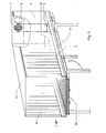
- Container 1 is an interchangeable container in the form of a box body of class C according to DIN EN 284 and DIN EN 283 for the transport and storage of flammable and non-flammable water-polluting liquids in cubic tank containers (KTC) and large packaging (IBC) as well as barrels , Canisters and other portable vessels. According to DIN EN 284, container 1 is made of steel.
- the box body is realized by two longitudinally extending side walls 2, 3, two end walls 4 (not shown), 5 and a roof 6, which are attached to a floor assembly.
- the end walls 4, 5 have ventilation openings 7, which are arranged offset in height from one another and each can be sealed tightly with a cover 8.
- Actuators 9 allow the actuation of the cover 8, which in this way allows the ventilation openings 7 to be opened or closed without the aid of conductors or the like. allow even in the raised state.
- the actuating elements 9 are designed in a manner known per se and allow locking by a locking mechanism, not shown here, which is located in the lower region of a cross member 13.
- the ventilation openings 7 are arranged offset in height, i.e. one of the two ventilation openings is near the floor, the other ventilation opening near the roof. Due to the difference in altitude, the air is automatically exchanged even at low air speeds.
- the ventilation openings 7 are designed as ventilation flaps.
- FIG. 2 The structure of the floor construction results in particular from FIG. 2. It essentially consists of a floor pan 10, which has a floor panel 11 profiled in the longitudinal direction. In the illustrated embodiment, the profiling is designed like a bead. It is initially used to strengthen the stability of the floor pan 10.
- the bottom plate 11 is connected to two laterally continuous longitudinal members 12 and two cross members 13 arranged on the end face, which are thus integral components of the bottom tray 10.
- Cross members 14 are arranged within the floor pan 10 between the longitudinal members 12 and connected to them. As further components of the floor pan 10, they impart the necessary final stability.
- the type of connection of base plate 11, side members 12 and cross members 13, 14 in the form of a welded connection is not shown in the exemplary embodiment shown.
- the base plate 11 can also be welded to the internal cross members 14.
- the cross member 14 is not continuously welded to the floor panel 11, but only in the raised portions.
- connection techniques such as gluing, are also particularly suitable for the connection between the inner cross members 14 and the floor panel 11.
- the floor pan 10 can be designed as a load-bearing element or directly as a floor group.
- the integrated side members 12 and cross members 13, 14 in connection with the profiled floor plate 11 allow an extremely flat design of the floor assembly, with a holding volume of 1250 liters being achievable in the present exemplary embodiment.
- the critical height of 240 mm for the floor assembly described at the outset is nevertheless not exceeded.
- the floor pan 10 therefore meets the relevant regulations.
- the cross members 14 extending within the floor pan 10 are U and square profiles.
- the floor grid in the form of a multiple arrangement of individual gratings 15 is placed directly on these. In the specific case, two rows of five gratings 15 are provided.
- the gratings 15 are designed to be sufficiently stable to ensure that the forklift truck or hand pallet truck can be driven on.
- the base trough 10 has a box-like contour course which recedes inwards.
- the resulting niches serve to receive the support legs 20 in the folded state. In this state, the support legs are shifted so far inwards that they do not protrude laterally and downwards from the outer contour of the container 1.
- the support legs 20 are each attached to a support bearing 21, the support bearings 21 being attached to the cross members 14 arranged within the base trough 10 for stability reasons with the interposition of the base plate 11. They are thus supported on the cross members 14.
- the floor pan 10 is expediently provided with a closable drain opening.
- a sight glass can be attached immediately adjacent, so that from the outside, i.e. without opening the container 1, the presence of any leaked liquid can be determined.
- Both the drain opening and the sight glass are in turn attached to a recessed section of the longitudinal beam 12 so that they do not protrude beyond the outer contour of the container 1.
- the floor pan 10 can be designed with a slight slope, so that any escaping liquid collects at a deepest point formed thereby. The drain opening and the sight glass are then assigned to this point.
- the base plate 11, the longitudinal beams 12 and the cross beams 13, 14 are made of stainless steel and are therefore resistant to most liquids to be transported and stored. If stainless steel is to be dispensed with for cost reasons, it is necessary to completely coat the floor pan 10 on the inside with a resistant material.
- a container 1 as an interchangeable container in accordance with DIN EN 284, which can be used as a transport container as well as a storage container. It has holding devices for rail and truck transportation and four support legs 20 according to DIN 70018. It is therefore possible to set up the container 1 for storing water-polluting liquids with or without the support legs 20 folded out. This results in floor clearances below the container 1 of 100 mm or 1220 mm.
- the two ventilation openings 7 allow the storage of flammable liquids of hazard classes Al, All and B. These are closed when the container 1 is used as a transport container.
- Container 1 also complies with a number of regulations, such as the Water Resources Act (WHG), the regulation of the storage of water-polluting substances (VLwF) and the technical rules for flammable liquids (TRbF). Approval as a transport container in accordance with the rules of the International Union of Railways (UIC) and CSC (safety approval in accordance with Federal Law Gazette 11 1976, p. 253) is also possible.
- WG Water Resources Act
- VLwF water-polluting substances
- TRbF technical rules for flammable liquids
Landscapes
- Engineering & Computer Science (AREA)
- Mechanical Engineering (AREA)
- Pallets (AREA)
- Packages (AREA)
- Refuse Collection And Transfer (AREA)
- Supplying Of Containers To The Packaging Station (AREA)
Applications Claiming Priority (2)
| Application Number | Priority Date | Filing Date | Title |
|---|---|---|---|
| DE4333793A DE4333793C2 (de) | 1993-10-04 | 1993-10-04 | Lager- und Transportbehälter |
| DE4333793 | 1993-10-04 |
Publications (3)
| Publication Number | Publication Date |
|---|---|
| EP0646532A2 true EP0646532A2 (fr) | 1995-04-05 |
| EP0646532A3 EP0646532A3 (fr) | 1996-01-24 |
| EP0646532B1 EP0646532B1 (fr) | 1997-01-02 |
Family
ID=6499365
Family Applications (1)
| Application Number | Title | Priority Date | Filing Date |
|---|---|---|---|
| EP94115527A Expired - Lifetime EP0646532B1 (fr) | 1993-10-04 | 1994-10-01 | Récipient de stockage et de transport |
Country Status (3)
| Country | Link |
|---|---|
| EP (1) | EP0646532B1 (fr) |
| AT (1) | ATE147047T1 (fr) |
| DE (2) | DE4333793C2 (fr) |
Cited By (3)
| Publication number | Priority date | Publication date | Assignee | Title |
|---|---|---|---|---|
| AT1138U1 (de) * | 1992-08-17 | 1996-11-25 | Zovos V O S | Behälter für problemstoffe |
| EP0761565A1 (fr) * | 1995-09-06 | 1997-03-12 | GERHARD ENGINEERING GmbH | Bac de protection d'un récipient |
| CN113212996A (zh) * | 2021-04-20 | 2021-08-06 | 中车太原机车车辆有限公司 | 一种集装箱联结装置及联结式集装箱 |
Family Cites Families (5)
| Publication number | Priority date | Publication date | Assignee | Title |
|---|---|---|---|---|
| DE2717396C2 (de) * | 1977-04-20 | 1979-05-03 | Ab Plastkarosser, Skellefteaa | Behälter zum Transportieren gefährlicher Güter |
| AT376179B (de) * | 1982-11-03 | 1984-10-25 | Hofstetter Michael | Abstuetzvorrichtung fuer container, wechselaufbauten od. dgl. von lastfahrzeugen |
| DE9005093U1 (de) * | 1990-05-04 | 1990-07-12 | Fr. Gerbracht Stahlblech- und Behälterbau GmbH & Co KG, 58730 Fröndenberg | Quaderförmiger Wechselbehälter für Lastkraftwagen und Anhänger |
| DE9103293U1 (de) * | 1991-03-18 | 1991-06-20 | Nukem GmbH, 8755 Alzenau | Behälter zum Transport insbesondere wassergefährdender Stoffe |
| GB2257123A (en) * | 1991-03-19 | 1993-01-06 | Adamson Modular Systems Limite | Swop body container jacking system. |
-
1993
- 1993-10-04 DE DE4333793A patent/DE4333793C2/de not_active Expired - Fee Related
-
1994
- 1994-10-01 AT AT94115527T patent/ATE147047T1/de not_active IP Right Cessation
- 1994-10-01 DE DE59401458T patent/DE59401458D1/de not_active Expired - Fee Related
- 1994-10-01 EP EP94115527A patent/EP0646532B1/fr not_active Expired - Lifetime
Cited By (3)
| Publication number | Priority date | Publication date | Assignee | Title |
|---|---|---|---|---|
| AT1138U1 (de) * | 1992-08-17 | 1996-11-25 | Zovos V O S | Behälter für problemstoffe |
| EP0761565A1 (fr) * | 1995-09-06 | 1997-03-12 | GERHARD ENGINEERING GmbH | Bac de protection d'un récipient |
| CN113212996A (zh) * | 2021-04-20 | 2021-08-06 | 中车太原机车车辆有限公司 | 一种集装箱联结装置及联结式集装箱 |
Also Published As
| Publication number | Publication date |
|---|---|
| ATE147047T1 (de) | 1997-01-15 |
| DE4333793C2 (de) | 1996-11-14 |
| EP0646532A3 (fr) | 1996-01-24 |
| DE4333793A1 (de) | 1995-04-06 |
| DE59401458D1 (de) | 1997-02-13 |
| EP0646532B1 (fr) | 1997-01-02 |
Similar Documents
| Publication | Publication Date | Title |
|---|---|---|
| DE202009018780U1 (de) | Großcontainer | |
| EP2147867B1 (fr) | Boîtier de stockage | |
| DE2313811A1 (de) | Aus kunststoff geformter behaelter | |
| DE202009010748U1 (de) | Vorrichtung zum Transport und/oder zur Lagerung von Gefahrgütern/Gefahrstoffen | |
| EP0646532B1 (fr) | Récipient de stockage et de transport | |
| DE2729737B2 (de) | Dicht verschließbarer, unterteilbarer Behälter | |
| DE102018118864A1 (de) | Container mit Transportgestell sowie Räder- und Reifentransportsystem | |
| DE102008005665A1 (de) | Großraumbehälter, insbesondere Container zur Lagerung und zum Transport von Gütern sowie ein Verfahren zum Segmentieren eines Großraumbehälters | |
| DE4320054C2 (de) | Zylindrischer Behälter | |
| DE102019105928A1 (de) | Transporteinrichtung, insbesondere Transportpalette | |
| WO1995010466A1 (fr) | Conteneur pour materiaux en vrac, muni d'un dispositif de vidage | |
| DE202021000806U1 (de) | Transportsystem mit einem modularen Behälter | |
| DE3908103C2 (fr) | ||
| DE20111561U1 (de) | Behälter zum Transport von Gütern | |
| WO2022184329A1 (fr) | Système de transport ayant un récipient modulaire | |
| DE102022109976A1 (de) | Grossladungsträger | |
| DE202010010624U1 (de) | Transportsystem | |
| EP0069921A1 (fr) | Cadre de changement pour véhicules de transport conteneur ayant des installations de verrouillage, comme camions, remorques ou wagons porte-conteneurs sur rails | |
| DE3545855A1 (de) | Transportbehaelter fuer wasser oder andere fluessigkeiten | |
| DE102015215098A1 (de) | Transportbehälter | |
| DE9208481U1 (de) | Lager-und Transportbehälter | |
| DE8813082U1 (de) | Transportkasten aus form- oder gießbarem Werkstoff, insbesondere Flaschenkasten aus Kunststoff | |
| DE202021100652U1 (de) | Anlage zum Fördern und Lagern von Transportgütern | |
| DE9100093U1 (de) | Behälter | |
| DE4108387A1 (de) | Auskleidung fuer prismatische gitterboxen |
Legal Events
| Date | Code | Title | Description |
|---|---|---|---|
| PUAI | Public reference made under article 153(3) epc to a published international application that has entered the european phase |
Free format text: ORIGINAL CODE: 0009012 |
|
| AK | Designated contracting states |
Kind code of ref document: A2 Designated state(s): AT CH DE LI NL |
|
| PUAL | Search report despatched |
Free format text: ORIGINAL CODE: 0009013 |
|
| AK | Designated contracting states |
Kind code of ref document: A3 Designated state(s): AT CH DE LI NL |
|
| 17P | Request for examination filed |
Effective date: 19960206 |
|
| GRAG | Despatch of communication of intention to grant |
Free format text: ORIGINAL CODE: EPIDOS AGRA |
|
| GRAH | Despatch of communication of intention to grant a patent |
Free format text: ORIGINAL CODE: EPIDOS IGRA |
|
| 17Q | First examination report despatched |
Effective date: 19960521 |
|
| GRAH | Despatch of communication of intention to grant a patent |
Free format text: ORIGINAL CODE: EPIDOS IGRA |
|
| GRAA | (expected) grant |
Free format text: ORIGINAL CODE: 0009210 |
|
| AK | Designated contracting states |
Kind code of ref document: B1 Designated state(s): AT CH DE LI NL |
|
| REF | Corresponds to: |
Ref document number: 147047 Country of ref document: AT Date of ref document: 19970115 Kind code of ref document: T |
|
| REG | Reference to a national code |
Ref country code: CH Ref legal event code: NV Representative=s name: DIPL.-ING. ETH H. R. WERFFELI PATENTANWALT Ref country code: CH Ref legal event code: EP |
|
| REF | Corresponds to: |
Ref document number: 59401458 Country of ref document: DE Date of ref document: 19970213 |
|
| PLBE | No opposition filed within time limit |
Free format text: ORIGINAL CODE: 0009261 |
|
| STAA | Information on the status of an ep patent application or granted ep patent |
Free format text: STATUS: NO OPPOSITION FILED WITHIN TIME LIMIT |
|
| 26N | No opposition filed | ||
| PGFP | Annual fee paid to national office [announced via postgrant information from national office to epo] |
Ref country code: CH Payment date: 19980907 Year of fee payment: 5 |
|
| PGFP | Annual fee paid to national office [announced via postgrant information from national office to epo] |
Ref country code: AT Payment date: 19981022 Year of fee payment: 5 |
|
| PG25 | Lapsed in a contracting state [announced via postgrant information from national office to epo] |
Ref country code: AT Free format text: LAPSE BECAUSE OF NON-PAYMENT OF DUE FEES Effective date: 19991001 |
|
| PGFP | Annual fee paid to national office [announced via postgrant information from national office to epo] |
Ref country code: NL Payment date: 19991027 Year of fee payment: 6 |
|
| PG25 | Lapsed in a contracting state [announced via postgrant information from national office to epo] |
Ref country code: LI Free format text: LAPSE BECAUSE OF NON-PAYMENT OF DUE FEES Effective date: 19991031 Ref country code: CH Free format text: LAPSE BECAUSE OF NON-PAYMENT OF DUE FEES Effective date: 19991031 |
|
| PGFP | Annual fee paid to national office [announced via postgrant information from national office to epo] |
Ref country code: DE Payment date: 19991127 Year of fee payment: 6 |
|
| REG | Reference to a national code |
Ref country code: CH Ref legal event code: PL |
|
| PG25 | Lapsed in a contracting state [announced via postgrant information from national office to epo] |
Ref country code: NL Free format text: LAPSE BECAUSE OF NON-PAYMENT OF DUE FEES Effective date: 20010501 |
|
| NLV4 | Nl: lapsed or anulled due to non-payment of the annual fee |
Effective date: 20010501 |
|
| PG25 | Lapsed in a contracting state [announced via postgrant information from national office to epo] |
Ref country code: DE Free format text: LAPSE BECAUSE OF NON-PAYMENT OF DUE FEES Effective date: 20010703 |