EP0646533B1 - Klemmvorrichtung - Google Patents
Klemmvorrichtung Download PDFInfo
- Publication number
- EP0646533B1 EP0646533B1 EP94307199A EP94307199A EP0646533B1 EP 0646533 B1 EP0646533 B1 EP 0646533B1 EP 94307199 A EP94307199 A EP 94307199A EP 94307199 A EP94307199 A EP 94307199A EP 0646533 B1 EP0646533 B1 EP 0646533B1
- Authority
- EP
- European Patent Office
- Prior art keywords
- clamping
- closure
- clamping devices
- mechanism according
- dish
- Prior art date
- Legal status (The legal status is an assumption and is not a legal conclusion. Google has not performed a legal analysis and makes no representation as to the accuracy of the status listed.)
- Expired - Lifetime
Links
Images
Classifications
-
- B—PERFORMING OPERATIONS; TRANSPORTING
- B65—CONVEYING; PACKING; STORING; HANDLING THIN OR FILAMENTARY MATERIAL
- B65G—TRANSPORT OR STORAGE DEVICES, e.g. CONVEYORS FOR LOADING OR TIPPING, SHOP CONVEYOR SYSTEMS OR PNEUMATIC TUBE CONVEYORS
- B65G69/00—Auxiliary measures taken, or devices used, in connection with loading or unloading
- B65G69/18—Preventing escape of dust
- B65G69/181—Preventing escape of dust by means of sealed systems
- B65G69/183—Preventing escape of dust by means of sealed systems with co-operating closure members on each of the parts of a separable transfer channel
-
- B—PERFORMING OPERATIONS; TRANSPORTING
- B65—CONVEYING; PACKING; STORING; HANDLING THIN OR FILAMENTARY MATERIAL
- B65D—CONTAINERS FOR STORAGE OR TRANSPORT OF ARTICLES OR MATERIALS, e.g. BAGS, BARRELS, BOTTLES, BOXES, CANS, CARTONS, CRATES, DRUMS, JARS, TANKS, HOPPERS, FORWARDING CONTAINERS; ACCESSORIES, CLOSURES, OR FITTINGS THEREFOR; PACKAGING ELEMENTS; PACKAGES
- B65D90/00—Component parts, details or accessories for large containers
- B65D90/54—Gates or closures
- B65D90/62—Gates or closures having closure members movable out of the plane of the opening
- B65D90/626—Gates or closures having closure members movable out of the plane of the opening having a linear motion
-
- B—PERFORMING OPERATIONS; TRANSPORTING
- B65—CONVEYING; PACKING; STORING; HANDLING THIN OR FILAMENTARY MATERIAL
- B65D—CONTAINERS FOR STORAGE OR TRANSPORT OF ARTICLES OR MATERIALS, e.g. BAGS, BARRELS, BOTTLES, BOXES, CANS, CARTONS, CRATES, DRUMS, JARS, TANKS, HOPPERS, FORWARDING CONTAINERS; ACCESSORIES, CLOSURES, OR FITTINGS THEREFOR; PACKAGING ELEMENTS; PACKAGES
- B65D2590/00—Component parts, details or accessories for large containers
- B65D2590/54—Gates or closures
- B65D2590/542—Gates or closures special sealing means or means for improving sealing
Definitions
- the invention relates to a clamping mechanism, particularly to such a mechanism as can be used for clamping a closure such as a cone seal in an aperture in say a container, hopper, silo, or intermediate bulk container (I.B.C.) which is used to store and/or transport, or mix, flowable material such as powder, granulated material or the like.
- a closure such as a cone seal in an aperture in say a container, hopper, silo, or intermediate bulk container (I.B.C.) which is used to store and/or transport, or mix, flowable material such as powder, granulated material or the like.
- I.B.C. intermediate bulk container
- a clamping mechanism for clamping together a closure and a body mounting same, comprising
- the first member may comprise a means to receive the body and a mount for the clamping devices, This provides for automatic operation.
- the means may comprise an annular dish-like member mounting the clamping devices. This is a relatively simple construction.
- the dish-like member may have a flared periphery for engagement by the body.
- the clamping devices may be secured to an inner boundary surface of the dish-like member by resilient mounting means. This provides for a positive clamping action.
- the resilient mounting means may each comprise a leaf spring. This is a relatively simple yet inexpensive construction.
- the clamping devices may each comprise a resilient member, such as a rubber block. This again is a relatively inexpensive construction.
- Each rubber block has an inclined surface for sealing engagement with an inclined surface of the body and closure. This again provides positive clamping action.
- the inclined surfaces may each be inclined at about 45° to the horizontal. This is a particularly effective construction.
- clamping devices there may be three clamping devices on the dish-like member. This is an effective arrangement, particularly as the clamping devices may be equiangularly mounted on the dish-like member.
- the second member may comprise an annular member of V-cross-section. This provides a simple yet effective over-centre part.
- holding means which may comprise an inflatable ring located in the 'V'. This provides a positive seating for the inflatable ring.
- a suction means there may be means to disengage the second member from engagement with the closure in the clamped operative position, particularly a suction means.
- a suction means may comprise a vacuum means.
- a materials handling system having a location station for receiving apparatus which can contain a flowable material, the location station comprising a mechanism as hereinbefore defined.
- apparatus including a closure comprising a valve system having a conical closure, and a mechanism as hereinbefore defined, for clamping the conical valve in an aperture of the system.
- the apparatus may comprise an intermediate bulk container.
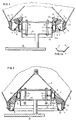
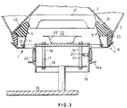
- a clamping mechanism 1 for clamping together a closure 2 and a body 3 mounting same comprising a first member 4 mounting a plurality of clamping devices 5 and a second member 6 having an over-centre part 7, the first and second members 4,6 being in engagement, the arrangement being such that when the body 3 engages the first member 4, the first and second members 4,6 move over-centre and the clamping devices 5 and the second member 6 engage the closure 2 whereby to clamp the closure 2 in the body 3.
- the first member 4 comprises an annular dish-like member which in the embodiment is a rolled angle ring made of for example light steel.
- the outer (as viewed) periphery has a flared entry part 8, and the inner boundary surface 9 has secured to it as by nuts and bolts 10 the plurality of the clamping devices 5.
- Each clamping device 5 comprises a resilient mounting means in the form of a leaf spring 11, suitably of light duty.
- the leaf spring 11 supports at an end remote from the first member 4 a resilient member in the form of a rubber block 12 which is secured to the leaf spring 11 by a suitable means such as a screw and block arrangement 13.
- the rubber blocks 12 are each of generally triangular arrangement, the base being of shallow 'V'-shape to provide an inclined surface 14, the angle of inclination being substantially 45° to the horizontal.
- the second member 6 is in the form of an annular member of substantially 'V'-section, the apex of the 'V' forming the over-centre part 7.
- the ring 6 seats in the first operative position on a beam or support-flange 14a, which is itself part of a central, in use, location frame 15 which is again itself part of a location station 16.
- the frame 15 has mounting posts 17 which pass through a base plate 18 and include springs 19, the clearance through the base plate 18 being a full clearance to provide a degree of lateral movement as well as movement in a substantially vertical sense. In this way, the frame 15 provides for inherent centring in use.
- retaining or holding means 20 for the second member which is in the form of an inflatable ring, which can be inflated and deflated through a line 21.
- the second member 6 is captive in the positions shown in Figs. 1 and 2, on the inflatable ring 20.
- the clamping mechanism 1 is located on the central part of the location frame 15.
- the mechanism is used to clamp the closure 2, in this case a conical cone valve, in an aperture 22 of a container such as an I.B.C., only part of the body 3 of which is shown.
- the body 3 of the I.B.C defines the aperture 22, obturated and opened depending on the position of the conical cone valve 2.
- the seal 23 is resilient too, and it has an upper (as viewed) inclined surface 24 inclined at substantially 45°.
- the surface of the flange 14 and surface 24 are thus complementary.
- the I.B.C In use to clamp the cone seal 2, the I.B.C, is lowered onto the location frame 15, being guided by a guide frame (note shown). At a certain height, the boundary surface of the body 3 of the I.B.C, defining the aperture 22 engages the flared perimeter 8 of the first member 4, and is located centrally. The lower part of the seal 23 of the I.B.C, and the surface 8 of the outer perimeter surface of the first member 4 engage in sealing relation and trap and seal any material which may be at the boundary so that it cannot escape. As the I.B.C, is lowered further, the first member 4 is drawn downwardly by the lowering force.
- the inherent resilience provided by the rubber block 12, resilient cone seals 23, the springs 19, and the tensile strength of the leaf springs 11 ensure that any out of kilter arrangement between the I.B.C. its cone 2 and the location station 16 is automatically compensated for so that a true centring and mounting is achieved, (Fig.2).
- the ring 20 may have been inflated during the lowering of the I.B.C.. If so, it is now deflated, thereby releasing the second member 6, so the whole I.B.C, can be simply lifted off the location station 16 by any suitable means, (Fig. 3), the second member 6 simply being lifted off the flange 14a.
- the cone valve 2 is now rigidly clamped in position, because the rubber blocks 12 are positively and solidly clamped between the second member 6 and the ring seal 23, thus creating a compressive force across the cone seal 2, through the second member 6, the rubber blocks 12 and the ring seal 23 to the body of the I.B.C. itself, thereby providing a totally tight, solid connection between the cone valve 2 and the mechanism 1, or transport cap, and this connection is virtually 100% fail-safe.
- the I.B.C. can then be transported, tumbled, moved, blended or handled however desired with no dislodgement of or leaking past the cone seal 2.
- the operational sequence described is reversed.
- the bin 2 (I.B.C.) is thus lowered onto the location frame 15 so that the second member 6 seats on the flange 14a and the ring 20 is inflated (Fig. 1).
- the I.B.C. is then lifted, the leaf springs 11 pass up over the 'V'-over-centre part 7 of the second member 6, and the leaf springs 11 then pivot automatically anti-clockwise, and the body 3 lifts off the first member 4, ready for another clamping sequence of operations.
- a complete system may be an integral part of the blender, the IBC entering and leaving the blender without a transport cap. This arrangement gives cost savings where there are a number of IBC's to be blended in one blender.
- the second member may be an inverted dish-like member 6' which may be removed from the cone in the position in Fig. 3 by suitable means such as suction means, for example a vacuum suction grabber or gripper 20'.
- suction means for example a vacuum suction grabber or gripper 20'.
Landscapes
- Engineering & Computer Science (AREA)
- Mechanical Engineering (AREA)
- Forklifts And Lifting Vehicles (AREA)
- Gripping Jigs, Holding Jigs, And Positioning Jigs (AREA)
- Steering Control In Accordance With Driving Conditions (AREA)
- Basic Packing Technique (AREA)
- Electrical Discharge Machining, Electrochemical Machining, And Combined Machining (AREA)
- Filling Or Emptying Of Bunkers, Hoppers, And Tanks (AREA)
- Closures For Containers (AREA)
- Clamps And Clips (AREA)
- Filling Of Jars Or Cans And Processes For Cleaning And Sealing Jars (AREA)
- Discharging, Photosensitive Material Shape In Electrophotography (AREA)
- Auxiliary Methods And Devices For Loading And Unloading (AREA)
- Seal Device For Vehicle (AREA)
Claims (12)
- Klemmechanismus zum Zusammenklemmen eines Verschlusses (2) und eines Körpers (3), an dem derselbe angebracht ist, gekennzeichnet durchein erstes Glied (4), das eine Mehrzahl federnd angebrachter Klemmvorrichtungen (5) umfaßt, die dazu angeordnet sind, den Verschluß (2) zu berühren, und die aus einer Freigabeposition in eine Klemmposition bewegt werden können, um den Verschluß (2) in dem Körper (3) zu klemmen, undein zweites Glied (6), das dazu angepaßt ist, die Klemmvorrichtungen (5) des ersten Glieds (4) zu berühren, um sie von der Freigabeposition in die Klemmposition zu bewegen und um die Klemmvorrichtungen (5) in der Klemmposition zu halten.
- Mechanismus nach Anspruch 1, dadurch gekennzeichnet, daß das erste Glied (4) ein Mittel umfaßt, das ein ringförmiges schalenartiges Glied umfaßt, an dem die Klemmvorrichtungen angebracht sind, um den Körper (3) aufzunehmen, und durch eine Halterung (10) für die Klemmvorrichtungen (5).
- Mechanismus nach Anspruch 2, dadurch gekennzeichnet, daß das schalenartige Glied eine konisch erweiterte Peripherie (8) zur Ineingriffnahme durch den Körper (3) aufweist, und dadurch, daß die Klemmvorrichtungen (5) mittels federnder Anbringungsmittel (11) an einer inneren Randoberfläche des schalenartigen Glieds befestigt sind.
- Mechanismus nach einem der vorhergehenden Ansprüche, dadurch gekennzeichnet, daß die Klemmvorrichtungen (5) jeweils ein federndes Glied umfassen.
- Mechanismus nach Anspruch 4, dadurch gekennzeichnet, daß die federnden Glieder (5) jeweils einen Gummiblock umfassen, der zum dichtenden Eingriff mit einer geneigten Oberfläche des Körpers und des Verschlusses eine geneigte Oberfläche aufweist.
- Mechanismus nach einem der Ansprüche 2 bis 5, dadurch gekennzeichnet, daß an dem schalenartigen Glied (8, 9) drei Klemmvorrichtungen (5) vorhanden sind, dadurch, daß das zweite Glied (6) ein ringförmiges Glied mit V-förmigem Querschnitt umfaßt, und dadurch, daß ein Mittel (20) dazu vorhanden ist, das erste und das zweite Glied (4, 6) im Eingriff in einer ersten Betriebsposition zu halten.
- Mechanismus nach Anspruch 6, dadurch gekennzeichnet, daß das Haltemittel (20) einen aufblasbaren Ring umfaßt, der sich in dem 'V' befindet.
- Mechanismus nach Anspruch 7, gekennzeichnet durch ein Mittel (20') dazu, in der geklemmten Betriebsposition das zweite Glied aus dem Eingriff mit dem Verschluß zu nehmen.
- Mechanismus nach Anspruch 8, dadurch gekennzeichnet, daß das Mittel (20') ein Vakuummittel umfaßt.
- Mechanismus nach einem der vorhergehenden Ansprüche, der in einer ersten Betriebsposition in einem Rahmen angebracht ist.
- Materialenhandhabungssystem, das eine Positionierungsstation zur Aufnahme einer Vorrichtung aufweist, die ein fließfähiges Material enthalten kann, dadurch gekennzeichnet, daß die Positionierungsstation (16) einen Mechanismus (1) nach einem der vorhergehenden Ansprüche umfaßt.
- Vorrichtung, die einen Verschluß umfaßt, der ein Ventilsystem mit einem konischen Verschluß umfaßt, gekennzeichnet durch einen Mechanismus (1) nach einem der vorhergehenden Ansprüche zum Klemmen des konischen Ventils (2) in einer Öffnung des Systems.
Applications Claiming Priority (2)
| Application Number | Priority Date | Filing Date | Title |
|---|---|---|---|
| GB939320387A GB9320387D0 (en) | 1993-10-04 | 1993-10-04 | A clamping mechanism |
| GB9320387 | 1993-10-04 |
Publications (3)
| Publication Number | Publication Date |
|---|---|
| EP0646533A2 EP0646533A2 (de) | 1995-04-05 |
| EP0646533A3 EP0646533A3 (de) | 1996-01-03 |
| EP0646533B1 true EP0646533B1 (de) | 1999-12-01 |
Family
ID=10742947
Family Applications (1)
| Application Number | Title | Priority Date | Filing Date |
|---|---|---|---|
| EP94307199A Expired - Lifetime EP0646533B1 (de) | 1993-10-04 | 1994-09-30 | Klemmvorrichtung |
Country Status (7)
| Country | Link |
|---|---|
| EP (1) | EP0646533B1 (de) |
| JP (1) | JP3524969B2 (de) |
| AT (1) | ATE187145T1 (de) |
| AU (1) | AU678043B2 (de) |
| DE (1) | DE69421881T2 (de) |
| ES (1) | ES2141804T3 (de) |
| GB (2) | GB9320387D0 (de) |
Families Citing this family (6)
| Publication number | Priority date | Publication date | Assignee | Title |
|---|---|---|---|---|
| AU712291B2 (en) * | 1994-07-11 | 1999-11-04 | Matcon (R & D) Limited | Material handling apparatus |
| GB9812204D0 (en) | 1998-06-05 | 1998-08-05 | Matcon R & D Ltd | A seal device |
| GB9818536D0 (en) * | 1998-08-25 | 1998-10-21 | Matcon R & D Ltd | Material handling apparatus |
| GB9823720D0 (en) | 1998-10-29 | 1998-12-23 | Matcon R & D Ltd | Materials handling apparatus |
| DE50104112D1 (de) * | 2001-06-28 | 2004-11-18 | Montena S A | Verschluss |
| CN117463638A (zh) * | 2023-10-31 | 2024-01-30 | 河南黄河旋风股份有限公司 | 全自动金刚石选型机及其选型方法 |
Family Cites Families (4)
| Publication number | Priority date | Publication date | Assignee | Title |
|---|---|---|---|---|
| GB705186A (en) * | 1951-04-27 | 1954-03-10 | George Alfred Darrington | Improvements in containers for transporting cement and like materials |
| CH635800A5 (en) * | 1979-03-02 | 1983-04-29 | Foerdertechnik Ag | Vertical outlet valve for pourable or flowable material. |
| GB8605521D0 (en) * | 1986-03-06 | 1986-04-09 | Material Control Eng Ltd | Handling apparatus |
| GB2212788B (en) * | 1987-11-27 | 1991-10-09 | Material Control Eng Ltd | Material handling apparatus |
-
1993
- 1993-10-04 GB GB939320387A patent/GB9320387D0/en active Pending
-
1994
- 1994-09-30 ES ES94307199T patent/ES2141804T3/es not_active Expired - Lifetime
- 1994-09-30 DE DE69421881T patent/DE69421881T2/de not_active Expired - Fee Related
- 1994-09-30 AT AT94307199T patent/ATE187145T1/de not_active IP Right Cessation
- 1994-09-30 GB GB9419704A patent/GB2282365B/en not_active Expired - Fee Related
- 1994-09-30 EP EP94307199A patent/EP0646533B1/de not_active Expired - Lifetime
- 1994-10-04 AU AU74396/94A patent/AU678043B2/en not_active Ceased
- 1994-10-04 JP JP26618694A patent/JP3524969B2/ja not_active Expired - Fee Related
Also Published As
| Publication number | Publication date |
|---|---|
| GB2282365B (en) | 1997-05-14 |
| AU7439694A (en) | 1995-04-13 |
| ES2141804T3 (es) | 2000-04-01 |
| JPH07232701A (ja) | 1995-09-05 |
| EP0646533A2 (de) | 1995-04-05 |
| DE69421881D1 (de) | 2000-01-05 |
| GB2282365A (en) | 1995-04-05 |
| AU678043B2 (en) | 1997-05-15 |
| EP0646533A3 (de) | 1996-01-03 |
| JP3524969B2 (ja) | 2004-05-10 |
| GB9320387D0 (en) | 1993-11-24 |
| GB9419704D0 (en) | 1994-11-16 |
| DE69421881T2 (de) | 2000-05-18 |
| ATE187145T1 (de) | 1999-12-15 |
Similar Documents
| Publication | Publication Date | Title |
|---|---|---|
| US4946071A (en) | Materials handling equipment | |
| US3171449A (en) | Apparatus for bulk handling of materials | |
| EP0547861B1 (de) | Vorrichtung und System zum kontaminationsfreien Übertragen von fliessfähigem Material zwischen Behältern | |
| JP2660305B2 (ja) | 物質処理システム | |
| EP0646533B1 (de) | Klemmvorrichtung | |
| CA1280083C (en) | Apparatus for emptying containers | |
| AU750037B2 (en) | Apparatus and system for handling material | |
| AU712291B2 (en) | Material handling apparatus | |
| US6685060B1 (en) | Material handling apparatus | |
| US5651472A (en) | Clamping mechanism for clamping closure member of a flowable material container and material handling system having such a clamping mechanism | |
| EP1279623B1 (de) | Füllverschluss für Behälter | |
| EP0560772A1 (de) | Beladevorrichtung für korpuskulare materialien | |
| EP1100733B1 (de) | Vorrichtung zum festhalten eines verschlusses eines ausgangs eines behälters für schüttgut | |
| GB2212788A (en) | Maintaining a loose valve in position when moving container | |
| GB2262514A (en) | Apparatus and system for filling a container. | |
| AU766965B2 (en) | Materials handling apparatus | |
| US7237311B2 (en) | Method and apparatus for securing a closure in an aperture of a container | |
| GB2377926A (en) | A through-fill closure with seal for a receptacle | |
| AU2001228675A1 (en) | Apparatus for securing a closure in an aperture of a container |
Legal Events
| Date | Code | Title | Description |
|---|---|---|---|
| PUAI | Public reference made under article 153(3) epc to a published international application that has entered the european phase |
Free format text: ORIGINAL CODE: 0009012 |
|
| AK | Designated contracting states |
Kind code of ref document: A2 Designated state(s): AT BE CH DE DK ES FR GB GR IE IT LI LU MC NL PT SE |
|
| PUAL | Search report despatched |
Free format text: ORIGINAL CODE: 0009013 |
|
| AK | Designated contracting states |
Kind code of ref document: A3 Designated state(s): AT BE CH DE DK ES FR GB GR IE IT LI LU MC NL PT SE |
|
| RHK1 | Main classification (correction) |
Ipc: B65D 90/62 |
|
| K1C1 | Correction of patent application (title page) published |
Effective date: 19950405 |
|
| 17P | Request for examination filed |
Effective date: 19960628 |
|
| 17Q | First examination report despatched |
Effective date: 19970403 |
|
| GRAG | Despatch of communication of intention to grant |
Free format text: ORIGINAL CODE: EPIDOS AGRA |
|
| GRAG | Despatch of communication of intention to grant |
Free format text: ORIGINAL CODE: EPIDOS AGRA |
|
| GRAH | Despatch of communication of intention to grant a patent |
Free format text: ORIGINAL CODE: EPIDOS IGRA |
|
| GRAH | Despatch of communication of intention to grant a patent |
Free format text: ORIGINAL CODE: EPIDOS IGRA |
|
| RAP1 | Party data changed (applicant data changed or rights of an application transferred) |
Owner name: MATCON (R & D) LIMITED |
|
| RIN1 | Information on inventor provided before grant (corrected) |
Inventor name: MATCON (R & D) LIMITED |
|
| GRAA | (expected) grant |
Free format text: ORIGINAL CODE: 0009210 |
|
| AK | Designated contracting states |
Kind code of ref document: B1 Designated state(s): AT BE CH DE DK ES FR GB GR IE IT LI LU MC NL PT SE |
|
| PG25 | Lapsed in a contracting state [announced via postgrant information from national office to epo] |
Ref country code: GR Free format text: LAPSE BECAUSE OF NON-PAYMENT OF DUE FEES Effective date: 19991201 Ref country code: AT Free format text: LAPSE BECAUSE OF FAILURE TO SUBMIT A TRANSLATION OF THE DESCRIPTION OR TO PAY THE FEE WITHIN THE PRESCRIBED TIME-LIMIT Effective date: 19991201 |
|
| REF | Corresponds to: |
Ref document number: 187145 Country of ref document: AT Date of ref document: 19991215 Kind code of ref document: T |
|
| ITF | It: translation for a ep patent filed | ||
| REG | Reference to a national code |
Ref country code: CH Ref legal event code: NV Representative=s name: A. BRAUN, BRAUN, HERITIER, ESCHMANN AG PATENTANWAE Ref country code: CH Ref legal event code: EP |
|
| REF | Corresponds to: |
Ref document number: 69421881 Country of ref document: DE Date of ref document: 20000105 |
|
| ET | Fr: translation filed | ||
| REG | Reference to a national code |
Ref country code: IE Ref legal event code: FG4D |
|
| PG25 | Lapsed in a contracting state [announced via postgrant information from national office to epo] |
Ref country code: DK Free format text: LAPSE BECAUSE OF FAILURE TO SUBMIT A TRANSLATION OF THE DESCRIPTION OR TO PAY THE FEE WITHIN THE PRESCRIBED TIME-LIMIT Effective date: 20000301 |
|
| PG25 | Lapsed in a contracting state [announced via postgrant information from national office to epo] |
Ref country code: PT Free format text: LAPSE BECAUSE OF FAILURE TO SUBMIT A TRANSLATION OF THE DESCRIPTION OR TO PAY THE FEE WITHIN THE PRESCRIBED TIME-LIMIT Effective date: 20000302 |
|
| REG | Reference to a national code |
Ref country code: ES Ref legal event code: FG2A Ref document number: 2141804 Country of ref document: ES Kind code of ref document: T3 |
|
| PLBE | No opposition filed within time limit |
Free format text: ORIGINAL CODE: 0009261 |
|
| STAA | Information on the status of an ep patent application or granted ep patent |
Free format text: STATUS: NO OPPOSITION FILED WITHIN TIME LIMIT |
|
| PG25 | Lapsed in a contracting state [announced via postgrant information from national office to epo] |
Ref country code: MC Free format text: THE PATENT HAS BEEN ANNULLED BY A DECISION OF A NATIONAL AUTHORITY Effective date: 20000930 Ref country code: LU Free format text: LAPSE BECAUSE OF NON-PAYMENT OF DUE FEES Effective date: 20000930 |
|
| 26N | No opposition filed | ||
| REG | Reference to a national code |
Ref country code: GB Ref legal event code: IF02 |
|
| PGFP | Annual fee paid to national office [announced via postgrant information from national office to epo] |
Ref country code: SE Payment date: 20020904 Year of fee payment: 9 |
|
| PGFP | Annual fee paid to national office [announced via postgrant information from national office to epo] |
Ref country code: FR Payment date: 20020910 Year of fee payment: 9 |
|
| PGFP | Annual fee paid to national office [announced via postgrant information from national office to epo] |
Ref country code: IE Payment date: 20020924 Year of fee payment: 9 |
|
| PGFP | Annual fee paid to national office [announced via postgrant information from national office to epo] |
Ref country code: GB Payment date: 20020925 Year of fee payment: 9 |
|
| PGFP | Annual fee paid to national office [announced via postgrant information from national office to epo] |
Ref country code: ES Payment date: 20020927 Year of fee payment: 9 |
|
| PGFP | Annual fee paid to national office [announced via postgrant information from national office to epo] |
Ref country code: NL Payment date: 20020930 Year of fee payment: 9 |
|
| PGFP | Annual fee paid to national office [announced via postgrant information from national office to epo] |
Ref country code: CH Payment date: 20021001 Year of fee payment: 9 |
|
| PGFP | Annual fee paid to national office [announced via postgrant information from national office to epo] |
Ref country code: DE Payment date: 20021011 Year of fee payment: 9 |
|
| PGFP | Annual fee paid to national office [announced via postgrant information from national office to epo] |
Ref country code: BE Payment date: 20021129 Year of fee payment: 9 |
|
| PG25 | Lapsed in a contracting state [announced via postgrant information from national office to epo] |
Ref country code: LI Free format text: LAPSE BECAUSE OF NON-PAYMENT OF DUE FEES Effective date: 20030930 Ref country code: IE Free format text: LAPSE BECAUSE OF NON-PAYMENT OF DUE FEES Effective date: 20030930 Ref country code: GB Free format text: LAPSE BECAUSE OF NON-PAYMENT OF DUE FEES Effective date: 20030930 Ref country code: CH Free format text: LAPSE BECAUSE OF NON-PAYMENT OF DUE FEES Effective date: 20030930 Ref country code: BE Free format text: LAPSE BECAUSE OF NON-PAYMENT OF DUE FEES Effective date: 20030930 |
|
| PG25 | Lapsed in a contracting state [announced via postgrant information from national office to epo] |
Ref country code: SE Free format text: LAPSE BECAUSE OF NON-PAYMENT OF DUE FEES Effective date: 20031001 Ref country code: ES Free format text: LAPSE BECAUSE OF NON-PAYMENT OF DUE FEES Effective date: 20031001 |
|
| BERE | Be: lapsed |
Owner name: *MATCON (R & D) LTD Effective date: 20030930 |
|
| PG25 | Lapsed in a contracting state [announced via postgrant information from national office to epo] |
Ref country code: NL Free format text: LAPSE BECAUSE OF NON-PAYMENT OF DUE FEES Effective date: 20040401 Ref country code: DE Free format text: LAPSE BECAUSE OF NON-PAYMENT OF DUE FEES Effective date: 20040401 |
|
| REG | Reference to a national code |
Ref country code: CH Ref legal event code: PL |
|
| GBPC | Gb: european patent ceased through non-payment of renewal fee |
Effective date: 20030930 |
|
| PG25 | Lapsed in a contracting state [announced via postgrant information from national office to epo] |
Ref country code: FR Free format text: LAPSE BECAUSE OF NON-PAYMENT OF DUE FEES Effective date: 20040528 |
|
| EUG | Se: european patent has lapsed | ||
| NLV4 | Nl: lapsed or anulled due to non-payment of the annual fee |
Effective date: 20040401 |
|
| REG | Reference to a national code |
Ref country code: IE Ref legal event code: MM4A |
|
| REG | Reference to a national code |
Ref country code: FR Ref legal event code: ST |
|
| REG | Reference to a national code |
Ref country code: ES Ref legal event code: FD2A Effective date: 20031001 |
|
| PG25 | Lapsed in a contracting state [announced via postgrant information from national office to epo] |
Ref country code: IT Free format text: LAPSE BECAUSE OF NON-PAYMENT OF DUE FEES;WARNING: LAPSES OF ITALIAN PATENTS WITH EFFECTIVE DATE BEFORE 2007 MAY HAVE OCCURRED AT ANY TIME BEFORE 2007. THE CORRECT EFFECTIVE DATE MAY BE DIFFERENT FROM THE ONE RECORDED. Effective date: 20050930 |