EP0646534B1 - Ausrichten von länglichen Gegenständen - Google Patents
Ausrichten von länglichen Gegenständen Download PDFInfo
- Publication number
- EP0646534B1 EP0646534B1 EP94307196A EP94307196A EP0646534B1 EP 0646534 B1 EP0646534 B1 EP 0646534B1 EP 94307196 A EP94307196 A EP 94307196A EP 94307196 A EP94307196 A EP 94307196A EP 0646534 B1 EP0646534 B1 EP 0646534B1
- Authority
- EP
- European Patent Office
- Prior art keywords
- objects
- conveyor means
- grid
- advance
- vibratory
- Prior art date
- Legal status (The legal status is an assumption and is not a legal conclusion. Google has not performed a legal analysis and makes no representation as to the accuracy of the status listed.)
- Expired - Lifetime
Links
Images
Classifications
-
- B—PERFORMING OPERATIONS; TRANSPORTING
- B07—SEPARATING SOLIDS FROM SOLIDS; SORTING
- B07C—POSTAL SORTING; SORTING INDIVIDUAL ARTICLES, OR BULK MATERIAL FIT TO BE SORTED PIECE-MEAL, e.g. BY PICKING
- B07C5/00—Sorting according to a characteristic or feature of the articles or material being sorted, e.g. by control effected by devices which detect or measure such characteristic or feature; Sorting by manually actuated devices, e.g. switches
- B07C5/02—Measures preceding sorting, e.g. arranging articles in a stream orientating
-
- B—PERFORMING OPERATIONS; TRANSPORTING
- B65—CONVEYING; PACKING; STORING; HANDLING THIN OR FILAMENTARY MATERIAL
- B65G—TRANSPORT OR STORAGE DEVICES, e.g. CONVEYORS FOR LOADING OR TIPPING, SHOP CONVEYOR SYSTEMS OR PNEUMATIC TUBE CONVEYORS
- B65G47/00—Article or material-handling devices associated with conveyors; Methods employing such devices
- B65G47/22—Devices influencing the relative position or the attitude of articles during transit by conveyors
- B65G47/24—Devices influencing the relative position or the attitude of articles during transit by conveyors orientating the articles
Definitions
- This invention relates to the aligning, or "laning” as it is often called, of elongated objects.
- the invention relates to a laning apparatus and method for aligning such elongated materials.
- the invention is particularly, although not exclusively, useful in relation to objects which are substantially cylindrical and, in particular, of an elongated cylindrical nature, such as sausages.
- objects need not be truly cylindrical and more conically shaped objects such as carrots can also equally be aligned by adopting the principles of the invention.
- US 4 717 027 shows a vibratory belt separator. Parts are placed on vibrating and advancing belts and objects as blow moulded are placed on these. Dross, i.e. unwanted pieces of plastic drop between the belts and are collected on a belt conveyor for recycling. The blown objects are not themselves intended to be aligned and even the dross is not intended to be aligned in any specific direction other than to fall between the belts.
- the invention has therefore been made with these problems in mind, and aims to provide apparatus and a method for aligning such objects far more quickly and accurately.
- apparatus for aligning elongated objects comprising an upper vibratory grid having a direction of advance of objects placed on it and having elongated openings arranged substantially parallel to one another and to the direction of advance and removal of the aligned objects, and beneath that vibratory grid, conveyor means including means for retaining the objects in their aligned orientation, for removing the objects from beneath the grid in a direction substantially parallel to the aligned orientation of such objects achieved as they fall through the elongated openings in the grid onto the conveyor means, the conveyor means being arranged to remove the aligned objects from beneath the vibrating grid at a higher linear speed than the speed of advance on the vibratory grid.
- the speed of removal of the items is not now limited by the speed of advance on a vibratory conveyor.
- the speed of removal is, by contrast, controlled by the speed of the conveyor means which can in fact be a relatively high speed in comparison with the speed of advance on the vibratory grid.
- the conveyor means moves at a linear speed of at least 0.5m/s, and most preferably 3m/s.
- the invention has the advantage of simplicity, since the various component parts consisting of the vibratory grid and the conveyor means can be very simple.
- the vibratory grid be made up of a number of parallel spaced bars.
- the elongated openings are then defined between adjacent pairs of bars and the spacing between the bars can be chosen so as to fit the width-wise size of the various elongated objects to be aligned.
- the bars are rounded in cross-section, but this is not essential.
- the bars have inclined sides so that the spacing between them, i.e. the width of the elongated openings, progressively decreases in a downward direction.
- the shaping of the bars as rounded is preferred, however, since this has the advantage that the inclined circular edges of the bars promote the alignment of the elongated object since there are only infinitely small flat areas on which the objects can rest and potentially remain non-aligned.
- the inclined curved edges tend to promote further alignment and the object then quickly and easily slips between the two bars and drops onto the conveyor means beneath.
- the vibratory grid may be desirable for the vibratory grid to advance the objects to be aligned in the same direction as the conveyor means.
- the vibratory grid can advance the objects in a direction opposite to the direction of the conveyor means so that if an object is too large to fit the elongated openings, it can be arranged to fall off the back of the grid, say, into a reject bin.
- the conveyor means ensure that the objects maintain their aligned orientation. This can be achieved by providing a number of elongated recesses or grooves in the belt aligned with the direction of its advance and the alignment direction of the objects as they drop on to a belt.
- the conveyor means comprises a plurality of pairs of spaced parallel endless bands.
- the aligned object will drop down onto a pair of spaced parallel bands positioned underneath elongated opening in the vibratory grid and immediately be picked up and supported by the bands but will rest very securely in the channel formed between the two bands, so maintaining its alignment. Desirably these bands are of round cross-section.
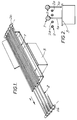
- a vibratory grid is composed of a number of spaced parallel rods 1. These are held on supports la at either end above a vibrator apparatus 3.
- the latter can be an entirely conventional piece of apparatus which is well known in the art of vibratory trays and conveyors and so does not need further description.
- Such vibrator apparatus is well known and readily available commercially.
- the spacing S between the rods 1 is chosen to suit the cross-sectional size or diameter of the objects to be aligned, which are simply dropped onto the rods 1 from a suitable hopper (not shown).
- a conveyor means 2 Beneath the vibratory grid 1 is provided a conveyor means 2.
- This comprises a number of spaced endless bands 2a which pass around rollers 2b at either end, one of which will be driven to advance the overall conveyor means 2 in the direction of the arrow A.
- the arrangement is such that there are two bands 2a beneath each opening between an adjacent pair of rods 1. Aligned objects therefore which fall through the openings between adjacent pairs of rods 1 will drop onto, rest between and be supported by a pair of bands 2a. In this way the alignment which has been achieved by the vibratory grid 1 is maintained.
- rods 1 and bands 2a each be of generally circular shape.
Landscapes
- Engineering & Computer Science (AREA)
- Mechanical Engineering (AREA)
- Attitude Control For Articles On Conveyors (AREA)
- Feeding Of Articles To Conveyors (AREA)
- Wrapping Of Specific Fragile Articles (AREA)
Claims (12)
- Vorrichtung zur Ausrichtung von länglichen Objekten, bestehend aus einem oberen Schüttelgitter (1) mit einer Bewegungsrichtung von darauf plazierten Objekten und mit im wesentlichen parallel zueinander und in Richtung der Bewegung der Objekte und der Entnahme der ausgerichteten Objekte angeordneten Längsöffnungen, und unterhalb dieses Schüttelgitters aus einer Fördereinrichtung (2) mit Einrichtungen zum Halten der Objekte in ihrer ausgerichteten Orientierungsrichtung, zur Entnahme der Objekte unterhalb des Gitters (1) in einer Richtung, die im wesentlichen parallel zur erzielten ausgerichteten Orientierungsrichtung solcher Objekte ist, wenn diese durch die Längsöffnungen im Gitter auf die Fördereinrichtung fallen, wobei die Fördereinrichtung (2) so angeordnet ist, daß die ausgerichteten Objekte unterhalb des Schüttelgitters (1) mit einer höheren linearen Geschwindigkeit entnommen werden als die Bewegungsgeschwindigkeit auf dem Schüttelgitter.
- Vorrichtung entsprechend Anspruch 1, bei der das Schüttelgitter aus einer Anzahl von parallel zueinander angeordneten Stäben (1) besteht und die Längsöffnungen zwischen den benachbarten Stabpaaren definiert werden.
- Vorrichtung entsprechend Anspruch 2, bei der die Stäbe (1) einen runden Querschnitt aufweisen.
- Vorrichtung entsprechend allen vorangehenden Ansprüchen, bei der das Schüttelgitter die Objekte in eine Richtung transportiert, die entgegengesetzt zur Richtung der Fördereinrichtung (2) verläuft, und ein Ausschußbehälter am Ende des Gitters (1) bereitgestellt wird, um Objekte aufzunehmen, die zu groß oder zu verformt sind, um durch die Längsöffnungen zu passen.
- Vorrichtung entsprechend allen vorangehenden Ansprüchen, bei der die Fördereinrichtung eine Vielzahl paarweise in bestimmten Abständen parallel angeordneter Endlosbänder (2a) aufweist.
- Vorrichtung entsprechend allen vorangehenden Ansprüchen, bei der eine zweite Fördereinrichtung verwendet wird, die mit einer höheren linearen Geschwindigkeit als die erste Fördereinrichtung (2) arbeitet und den Abstand zwischen den Objekten in Förderrichtung weiter vergrößert.
- Verfahren zur Ausrichtung länglicher Objekte, bei dem diese auf einem Schüttelgitter (1) einer Vibration ausgesetzt sind, so daß die Objekte auf dem Gitter transportiert werden, und das Gitter Langsöffnungen aufweist, die im wesentlichen parallel zueinander und zur Bewegungsrichtung und zur beabsichtigten Ausrichtungsrichtung der Objekte angeordnet sind, und die Objekte, wenn sie beim Erreichen dieser Längsöffnungen eine geeignete Ausrichtung erreicht haben, durch diese Längsöffnungen auf eine Fördereinrichtung (2) fallen, auf der die Objekte in ihrer ausgerichteten Orientierungsrichtung gehalten und unterhalb des Schüttelgitters (1) in der Richtung ihrer Ausrichtung mit einer höheren linearen Geschwindigkeit entnommen werden als der Bewegungsgeschwindigkeit auf dem Schüttelgitter.
- Verfahren entsprechend Anspruch 7, bei dem sich die Fördereinrichtung (2) mit einer linearen Geschwindigkeit von mindestens 0,5 m/s bewegt.
- Verfahren entsprechend Anspruch 7, bei dem sich die Fördereinrichtung (2) mit einer linearen Geschwindigkeit von mindestens 3 m/s bewegt.
- Verfahren entsprechend den vorangehenden Ansprüchen 7 bis 9, bei dem die Fördereinrichtung (2) eine Vielzahl paarweise in bestimmten Abständen parallel angeordneter Endlosbänder aufweist, wobei jeweils ein Paar unterhalb einer Längsöffnung im Schüttelgitter (1) verläuft, so daß Objekte, welche durch das Fallen durch die Längsöffnung ausgerichtet sind, auf und zwischen dem jeweiligen Bandpaar ruhen und durch die Bänder in dieser Ausrichtung gehalten werden.
- Verfahren entsprechend den vorangehenden Ansprüchen 7 bis 10, bei dem die Bewegungsrichtung der Objekte über das Schüttelgitter (1) entgegengesetzt zur Entnahmerichtung der Fördereinrichtung (2) ist.
- Verfahren entsprechend den vorangehenden Ansprüchen 7 bis 11, bei dem eine zweite Fördereinrichtung verwendet wird, die mit einer höheren linearen Geschwindigkeit als die erste Fördereinrichtung (2) arbeitet und auf welche die Objekte von der ersten Fördereinrichtung (2) fallen, so daß der Abstand zwischen den Objekten in Förderrichtung vergrößert wird.
Applications Claiming Priority (2)
| Application Number | Priority Date | Filing Date | Title |
|---|---|---|---|
| GB9320279 | 1993-10-01 | ||
| GB939320279A GB9320279D0 (en) | 1993-10-01 | 1993-10-01 | The aligning of elongated objects |
Publications (2)
| Publication Number | Publication Date |
|---|---|
| EP0646534A1 EP0646534A1 (de) | 1995-04-05 |
| EP0646534B1 true EP0646534B1 (de) | 1998-06-17 |
Family
ID=10742851
Family Applications (1)
| Application Number | Title | Priority Date | Filing Date |
|---|---|---|---|
| EP94307196A Expired - Lifetime EP0646534B1 (de) | 1993-10-01 | 1994-09-30 | Ausrichten von länglichen Gegenständen |
Country Status (5)
| Country | Link |
|---|---|
| US (1) | US5641073A (de) |
| EP (1) | EP0646534B1 (de) |
| DE (1) | DE69411112T2 (de) |
| ES (1) | ES2119088T3 (de) |
| GB (1) | GB9320279D0 (de) |
Families Citing this family (4)
| Publication number | Priority date | Publication date | Assignee | Title |
|---|---|---|---|---|
| NL1006555C2 (nl) * | 1997-07-11 | 1999-01-12 | Con Weigh Beheer B V | Inrichting bestemd voor het inspecteren, sorteren en/of doseren van chaotisch geordende voorwerpen. |
| IT1304423B1 (it) * | 1998-11-18 | 2001-03-19 | Gd Spa | Metodo di alimentazione di sigarette ad una bocca di uscita di unatramoggia. |
| US6135263A (en) * | 1998-12-11 | 2000-10-24 | Williams; Roger S. | Apparatus for organizing and delivering cylindrical and elongate articles from a random disorderly supply |
| DE10050739C1 (de) * | 2000-10-13 | 2002-02-28 | Sim Automation Gmbh & Co Kg | Vorrichtung zur Umorientierung von als Schüttgut handhabbaren Teilen, die von einem Industrieroboter erfasst werden |
Family Cites Families (11)
| Publication number | Priority date | Publication date | Assignee | Title |
|---|---|---|---|---|
| SE321400B (de) * | 1964-07-01 | 1970-03-02 | F Mogensen | |
| US3339703A (en) * | 1966-03-01 | 1967-09-05 | Reynolds Tobacco Co R | Apparatus for rearranging randomly oriented elongated articles into endwise orientation |
| US3528160A (en) * | 1967-12-05 | 1970-09-15 | Ibm | Apparatus and process for handling needle-like objects |
| FR2134224B1 (de) * | 1971-04-28 | 1975-02-21 | Dubuit Louis | |
| DE3066455D1 (en) * | 1979-03-20 | 1984-03-15 | Wentcroft Engs Ltd | A device for arranging in order a random supply of articles |
| US4494919A (en) * | 1982-09-20 | 1985-01-22 | Macmillan Bloedel Limited | Apparatus for laying a mat of wood strands |
| SE435687B (sv) * | 1983-10-06 | 1984-10-15 | Gen Production And Planning Ab | Forfarande for sallning av treflis och liknande samt ett sall |
| NL8501251A (nl) * | 1985-05-02 | 1986-12-01 | Backus Sormac | Sorteerinrichting. |
| US4717027A (en) * | 1986-03-28 | 1988-01-05 | Laros Equipment Company, Inc. | Vibratory belt separator for blow-molded parts |
| US5117983A (en) * | 1989-08-07 | 1992-06-02 | Weyerhaeuser Company | Bar screen having a reciprocating action |
| US5058749A (en) * | 1990-06-19 | 1991-10-22 | Jung-Mei Jong Chiu | Apparatus for sorting articles according to size |
-
1993
- 1993-10-01 GB GB939320279A patent/GB9320279D0/en active Pending
-
1994
- 1994-09-28 US US08/314,214 patent/US5641073A/en not_active Expired - Lifetime
- 1994-09-30 ES ES94307196T patent/ES2119088T3/es not_active Expired - Lifetime
- 1994-09-30 DE DE69411112T patent/DE69411112T2/de not_active Expired - Lifetime
- 1994-09-30 EP EP94307196A patent/EP0646534B1/de not_active Expired - Lifetime
Also Published As
| Publication number | Publication date |
|---|---|
| EP0646534A1 (de) | 1995-04-05 |
| US5641073A (en) | 1997-06-24 |
| DE69411112D1 (de) | 1998-07-23 |
| ES2119088T3 (es) | 1998-10-01 |
| GB9320279D0 (en) | 1993-11-17 |
| DE69411112T2 (de) | 1999-01-14 |
Similar Documents
| Publication | Publication Date | Title |
|---|---|---|
| US7311191B2 (en) | Conveyor system for singulating and orienting | |
| US5291983A (en) | Apparatus for aligning and uniformly orienting fish | |
| JPS5990683A (ja) | 細長い物品を分類するための装置及び方法 | |
| EP0095816A2 (de) | Ausricht- und Förderanlage für Gegenstände | |
| US5641073A (en) | Aligning of elongated objects | |
| EP0345036B1 (de) | Förderer mit Abgabevorrichtung | |
| DE69312845T2 (de) | Sortierförderer mit magnetischer Entladung | |
| US3698552A (en) | Sorting machine | |
| EP0294070B1 (de) | Gerät zum Handhaben von Körpern allgemein zylindrischer Gestalt | |
| JP4857474B2 (ja) | 果実の選別装置 | |
| US4078652A (en) | Article feeder | |
| DE19945037A1 (de) | Vorrichtung zum Ausrichten und gegebenenfalls Sortieren von länglichen Partikeln | |
| US4466545A (en) | Article grading apparatus | |
| KR102461114B1 (ko) | 비산식 마늘 선별 장치 | |
| JPS62111864A (ja) | 巻物細長片搬送装置 | |
| JP2596656B2 (ja) | 作物の選別用搬送装置 | |
| JP4990537B2 (ja) | 果菜選別方法と果菜選別装置と果菜選別装置用果菜搬送体と果菜選別装置用スライド体 | |
| JP2900442B2 (ja) | 玉ねぎ等の形状選別装置 | |
| JP2582960B2 (ja) | 作物の選別用搬送装置 | |
| US4253574A (en) | Apparatus and method for sorting pickles | |
| JP7770298B2 (ja) | 豆類選別機 | |
| JPS6118485A (ja) | 果実・そ菜類の選別装置 | |
| JPS6129513Y2 (de) | ||
| JPH0125670Y2 (de) | ||
| JPS5842066Y2 (ja) | 果物等の選別装置 |
Legal Events
| Date | Code | Title | Description |
|---|---|---|---|
| PUAI | Public reference made under article 153(3) epc to a published international application that has entered the european phase |
Free format text: ORIGINAL CODE: 0009012 |
|
| AK | Designated contracting states |
Kind code of ref document: A1 Designated state(s): BE DE ES FR GB IT NL |
|
| 17P | Request for examination filed |
Effective date: 19950713 |
|
| 17Q | First examination report despatched |
Effective date: 19960930 |
|
| GRAG | Despatch of communication of intention to grant |
Free format text: ORIGINAL CODE: EPIDOS AGRA |
|
| GRAG | Despatch of communication of intention to grant |
Free format text: ORIGINAL CODE: EPIDOS AGRA |
|
| GRAG | Despatch of communication of intention to grant |
Free format text: ORIGINAL CODE: EPIDOS AGRA |
|
| GRAH | Despatch of communication of intention to grant a patent |
Free format text: ORIGINAL CODE: EPIDOS IGRA |
|
| GRAH | Despatch of communication of intention to grant a patent |
Free format text: ORIGINAL CODE: EPIDOS IGRA |
|
| GRAA | (expected) grant |
Free format text: ORIGINAL CODE: 0009210 |
|
| AK | Designated contracting states |
Kind code of ref document: B1 Designated state(s): BE DE ES FR GB IT NL |
|
| REF | Corresponds to: |
Ref document number: 69411112 Country of ref document: DE Date of ref document: 19980723 |
|
| ET | Fr: translation filed | ||
| ITF | It: translation for a ep patent filed | ||
| REG | Reference to a national code |
Ref country code: ES Ref legal event code: FG2A Ref document number: 2119088 Country of ref document: ES Kind code of ref document: T3 |
|
| PLBE | No opposition filed within time limit |
Free format text: ORIGINAL CODE: 0009261 |
|
| STAA | Information on the status of an ep patent application or granted ep patent |
Free format text: STATUS: NO OPPOSITION FILED WITHIN TIME LIMIT |
|
| 26N | No opposition filed | ||
| PGFP | Annual fee paid to national office [announced via postgrant information from national office to epo] |
Ref country code: ES Payment date: 19990920 Year of fee payment: 6 |
|
| PG25 | Lapsed in a contracting state [announced via postgrant information from national office to epo] |
Ref country code: ES Free format text: LAPSE BECAUSE OF NON-PAYMENT OF DUE FEES Effective date: 20001001 |
|
| REG | Reference to a national code |
Ref country code: GB Ref legal event code: IF02 |
|
| REG | Reference to a national code |
Ref country code: ES Ref legal event code: FD2A Effective date: 20011011 |
|
| PG25 | Lapsed in a contracting state [announced via postgrant information from national office to epo] |
Ref country code: IT Free format text: LAPSE BECAUSE OF NON-PAYMENT OF DUE FEES Effective date: 20050930 |
|
| REG | Reference to a national code |
Ref country code: GB Ref legal event code: 732E |
|
| REG | Reference to a national code |
Ref country code: FR Ref legal event code: TP |
|
| BECA | Be: change of holder's address |
Owner name: FOWLER WESTRUP INDIA PRIVATE LTDRAJ MAHAL BUILDING Effective date: 20090527 |
|
| NLS | Nl: assignments of ep-patents |
Owner name: FOWLER WESTRUP INDIA (PRIVATE) LIMITED Effective date: 20090528 |
|
| PGFP | Annual fee paid to national office [announced via postgrant information from national office to epo] |
Ref country code: NL Payment date: 20090924 Year of fee payment: 16 Ref country code: GB Payment date: 20090929 Year of fee payment: 16 |
|
| PGFP | Annual fee paid to national office [announced via postgrant information from national office to epo] |
Ref country code: DE Payment date: 20090929 Year of fee payment: 16 |
|
| PGFP | Annual fee paid to national office [announced via postgrant information from national office to epo] |
Ref country code: BE Payment date: 20091026 Year of fee payment: 16 |
|
| BERE | Be: lapsed |
Owner name: FOWLER WESTRUP INDIA PRIVATE LTD Effective date: 20100930 |
|
| REG | Reference to a national code |
Ref country code: NL Ref legal event code: V1 Effective date: 20110401 |
|
| GBPC | Gb: european patent ceased through non-payment of renewal fee |
Effective date: 20100930 |
|
| REG | Reference to a national code |
Ref country code: FR Ref legal event code: ST Effective date: 20110531 |
|
| REG | Reference to a national code |
Ref country code: DE Ref legal event code: R119 Ref document number: 69411112 Country of ref document: DE Effective date: 20110401 |
|
| PG25 | Lapsed in a contracting state [announced via postgrant information from national office to epo] |
Ref country code: BE Free format text: LAPSE BECAUSE OF NON-PAYMENT OF DUE FEES Effective date: 20100930 Ref country code: FR Free format text: LAPSE BECAUSE OF NON-PAYMENT OF DUE FEES Effective date: 20100930 Ref country code: DE Free format text: LAPSE BECAUSE OF NON-PAYMENT OF DUE FEES Effective date: 20110401 |
|
| PG25 | Lapsed in a contracting state [announced via postgrant information from national office to epo] |
Ref country code: GB Free format text: LAPSE BECAUSE OF NON-PAYMENT OF DUE FEES Effective date: 20100930 Ref country code: NL Free format text: LAPSE BECAUSE OF NON-PAYMENT OF DUE FEES Effective date: 20110401 |
|
| PGFP | Annual fee paid to national office [announced via postgrant information from national office to epo] |
Ref country code: FR Payment date: 20091006 Year of fee payment: 16 |