EP0646539B1 - Cadre de préhension de container - Google Patents
Cadre de préhension de container Download PDFInfo
- Publication number
- EP0646539B1 EP0646539B1 EP94115652A EP94115652A EP0646539B1 EP 0646539 B1 EP0646539 B1 EP 0646539B1 EP 94115652 A EP94115652 A EP 94115652A EP 94115652 A EP94115652 A EP 94115652A EP 0646539 B1 EP0646539 B1 EP 0646539B1
- Authority
- EP
- European Patent Office
- Prior art keywords
- beams
- cross
- extension
- chain
- container
- Prior art date
- Legal status (The legal status is an assumption and is not a legal conclusion. Google has not performed a legal analysis and makes no representation as to the accuracy of the status listed.)
- Expired - Lifetime
Links
- 230000008878 coupling Effects 0.000 claims description 6
- 238000010168 coupling process Methods 0.000 claims description 6
- 238000005859 coupling reaction Methods 0.000 claims description 6
- 239000013013 elastic material Substances 0.000 claims description 3
- 230000000712 assembly Effects 0.000 claims 1
- 238000000429 assembly Methods 0.000 claims 1
- 238000004519 manufacturing process Methods 0.000 description 3
- 238000000034 method Methods 0.000 description 3
- 230000015572 biosynthetic process Effects 0.000 description 2
- 239000000463 material Substances 0.000 description 2
- 230000015556 catabolic process Effects 0.000 description 1
- 238000010276 construction Methods 0.000 description 1
- 238000009826 distribution Methods 0.000 description 1
- 230000000694 effects Effects 0.000 description 1
- 229920001971 elastomer Polymers 0.000 description 1
- 238000005516 engineering process Methods 0.000 description 1
- 230000001747 exhibiting effect Effects 0.000 description 1
- 230000007257 malfunction Effects 0.000 description 1
- 238000005259 measurement Methods 0.000 description 1
- 229920002635 polyurethane Polymers 0.000 description 1
- 239000004814 polyurethane Substances 0.000 description 1
- 238000009877 rendering Methods 0.000 description 1
- 239000012858 resilient material Substances 0.000 description 1
- 239000000725 suspension Substances 0.000 description 1
- 230000001360 synchronised effect Effects 0.000 description 1
- 238000003466 welding Methods 0.000 description 1
Images



Classifications
-
- B—PERFORMING OPERATIONS; TRANSPORTING
- B66—HOISTING; LIFTING; HAULING
- B66C—CRANES; LOAD-ENGAGING ELEMENTS OR DEVICES FOR CRANES, CAPSTANS, WINCHES, OR TACKLES
- B66C1/00—Load-engaging elements or devices attached to lifting or lowering gear of cranes or adapted for connection therewith for transmitting lifting forces to articles or groups of articles
- B66C1/10—Load-engaging elements or devices attached to lifting or lowering gear of cranes or adapted for connection therewith for transmitting lifting forces to articles or groups of articles by mechanical means
- B66C1/101—Load-engaging elements or devices attached to lifting or lowering gear of cranes or adapted for connection therewith for transmitting lifting forces to articles or groups of articles by mechanical means for containers
-
- B—PERFORMING OPERATIONS; TRANSPORTING
- B66—HOISTING; LIFTING; HAULING
- B66C—CRANES; LOAD-ENGAGING ELEMENTS OR DEVICES FOR CRANES, CAPSTANS, WINCHES, OR TACKLES
- B66C1/00—Load-engaging elements or devices attached to lifting or lowering gear of cranes or adapted for connection therewith for transmitting lifting forces to articles or groups of articles
- B66C1/10—Load-engaging elements or devices attached to lifting or lowering gear of cranes or adapted for connection therewith for transmitting lifting forces to articles or groups of articles by mechanical means
- B66C1/62—Load-engaging elements or devices attached to lifting or lowering gear of cranes or adapted for connection therewith for transmitting lifting forces to articles or groups of articles by mechanical means comprising article-engaging members of a shape complementary to that of the articles to be handled
- B66C1/66—Load-engaging elements or devices attached to lifting or lowering gear of cranes or adapted for connection therewith for transmitting lifting forces to articles or groups of articles by mechanical means comprising article-engaging members of a shape complementary to that of the articles to be handled for engaging holes, recesses, or abutments on articles specially provided for facilitating handling thereof
- B66C1/663—Load-engaging elements or devices attached to lifting or lowering gear of cranes or adapted for connection therewith for transmitting lifting forces to articles or groups of articles by mechanical means comprising article-engaging members of a shape complementary to that of the articles to be handled for engaging holes, recesses, or abutments on articles specially provided for facilitating handling thereof for containers
Definitions
- the present invention relates to a container yoke according to the preamble of claim 1.
- a yoke or lifting frame which includes a central frame beam and cross-beams which are mounted on the ends of the frame beam, on extension beams, and which are able to move in relation to the frame beam.
- the free ends of the cross-beams form the four corners of the container yoke or lifting frame and have mounted thereon downwardly depending lifting hooks which can be turned reciprocatingly through ninety degrees with the aid of a hydraulic system for instance, thereby to engage and disengage corresponding apertures provided at the top of the four corners of the container. Because the cross-beams are able to move, the distance between the cross-beams can be altered to adjust the container yoke to containers of different lengths.
- the weight of the yoke, or lifting frame, together with its electric and hydraulic assembly, which functions to maneuver the extension beams and lifting hooks among other things, is quite considerable.
- the containers handled may be extremely heavy.
- all container yokes, or lifting frames are handled more or less roughly, it will be understood that great demands are placed on the mechanical strength of all carrying parts, so that these parts will be able to resist the formation of cracks and other forms of fatigue. This demand is met by dimensioning all bars, beams and connections so that, wherever possible, the yoke will be sufficiently strong to withstand all uneven loads to which the container may be subjected.
- two extension beams together with their respective cross-beams form a welded unit which is moved into an out of the main beams between positions of 20,40 and 45 feet in length (standard measurements) .
- a cross-beam or extension beam will often be damaged in some way or another, requiring the beam to be replaced, despite the robust dimensions of the container yoke.
- any repair work is a time consuming and expensive operation.
- the welded unit is difficult to manufacture, since it is imperative that the longitudinally extending extension beams are parallel with one another.
- yoke provided in WO-A-8103323 which comprises a central frame unit having parts of side beams adapted to be extended and retracted in relation to the frame unit. At the outer ends said pairs of side beams 3,4 are rigidly connected by cross-bars. The outward and inward shifting of the pairs of the side beams is performed with the pair of specific operating arms which are elastically coupled to the cross-bars.
- extension beams and cross-beams enables a considerable part of the energy contained in blows and impacts to be absorbed, so that the impact forces will not propagate in the yoke and cause problems with regard to other components, such as the electrical and hydraulic assembly.
- extension beams and cross-bums can be replaced individually when damaged, at a much lower cost than is the case at present.
- the user may have a extension beam and a crossbeam in stock and therewith enable a damaged extension beam and cross-beam to be replaced and the yoke therewith made serviceable again, and then optionally repair the damaged parts.
- the invention thus increases the availability of a container yoke in accordance with the invention, both because the risk of damage is much smaller than in the case of known yoke constructions, and also because the idle time is drastically reduced in the case of damage to the yoke.
- extension beams and cross-beams - and parallelism with regard to the extension beams is achieved by guidance in the yoke frame and not as a result of welding extension beams and cross-beams together.
- the couplings are constructed so as to enable them to be easily changed, meaning in turn that should, for instance, a cross-beam fasten on a container in a ship's cell, the whole of the cross-beam can be removed and replaced with another, thereby enabling the yoke to be used again within the space of thirty minutes or so.
- the electrical and hydraulic assembly of the container yoke has been mounted in a separate frame structure which also accommodates the means required for maneuvering the cross-beams. This further improves the availability of the container yoke should part of the assembly responsible for maneuvering the lifting hooks or the extension beams malfunction or break-down.
- the separate frame in which the power-unit is mounted in accordance with the invention is hung from and secured between the main beams which form the container yoke and which are separated from one another in pairs, and the push rods which function to move the cross-beams are connected to the extension beams so that impact forces acting on the cross-beams will not be transmitted directly to the power assembly.
- Figure 1 is a schematic illustration of the container yoke, although neither the yoke lifting connections nor the yoke lifting hooks have been shown, these hooks being mounted at the ends of the cross-beams and depending downwards for engagement with the four corners of a container.
- the yoke is comprised of four main beams 1, in the form of box beams. Two extension beams 2 can be moved in the main beams 1 in one direction, whereas two other extension beams 2 can be moved in the other direction in said main beams.
- the free ends of extension beams 2 carry a respective cross-beam 3.
- the cross-beams are provided at their free ends with lifting hooks, so-called twist locks, which can be twisted and engaged in corresponding recesses on a container to be lifted.
- the yoke is constructed in accordance with known technology.
- the cross-beams are connected to the extension beams with the aid fastening means in the form of elastic couplings or connectors 4.
- Figure 3 is a sectional view on the line III-III in Figure 1, through one part of the end-beam and through the ends of two extension beams.
- the outer ends of respective extension beams are provided with two axially directed flanges 5.
- the cross-beam 3 include a beam-like part 6 and a plate 7 which is upstanding from the beam-like part. Extending from the plate 7 are two projections or springs 8, which extend in between the flanges 5 of respective extension beams 2.
- respective couplings 4 include two mutually concentrical sleeves 9 which contain an elastic or resilient material 10 therebetween.
- the elastic material 10 may be rubber but is preferably polyurethane, this latter material exhibiting the desired qualities and properties.
- the material is vulcanized to the sleeves 9, for instance.
- the outer sleeve is attached, welded, to the spring 8 of the cross-beam 3, whereas a bolt 11 extends through the inner sleeve 9 and passes through openings in the extension-beam flanges 5 corresponding to the bolt.
- the bolt 11 is secured in place with the aid of suitable means (for instance with a nut, not shown) obvious to those of normal skill in the art.
- the extension beams 2 are connected pairwise to a cross-beam 3 and in order for the container yoke to function satisfactorily it is necessary for the extension beams to move in parallel and synchronously with one another.
- the beams are driven by push rods 12 which are bound synchronously with one another, see Figure 4. For instance, two pairs of bottom push rods (12, only one is shown in Figure 4) drive the cross-beam shown on the left in Figure 2, whereas two top push rods 12 (only one of which is shown in Figure 2) drive the cross-beam shown to the right in the Figure.
- the chain wheel 16 is instrumental in driving the push rods 12 of one pair, which are driven synchronously in a respective direction, with an axle non-rotatably connected to a corresponding chain wheel which drives the other pair of push rods (see Figure 2). Extending between the pair of push rods 12 are two chains 18.
- One end of respective chains 18 is fastened to the frame 14 (at 19) and passes over the first guide chain-wheel 13 of a push rod and back over the chain wheel 16, and from there back along the push rod 12 to its outer end, where the chain is secured (at 20).
- Shown in Figure 4 is a fixed guide chain-wheel or fixed semi-circular chain-wheel ring 21, whose purpose is to improve distribution of the load on the chain at this end.
- the chain that coacts with the upper push rod 12 runs along a similar path, although this time over the chain wheel 15 which in this embodiment is freely rotatable on an axle 22 common with the axle of a corresponding chain wheel coacting with the second pair of push rods.
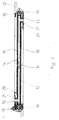
- Figure 2 illustrates principally the manner in which the separate frame 14, the push rods 12 and chains 8 are suspended between the pairs of mutually adjacent main beams 1.
- Figures 2 and 5 also show the hydraulic unit 24 and the electric unit 25 necessary for powering the container yoke, these units also being mounted on and carried by the frame 14, therewith forming a unit which can be fitted easily ton the inventive container yoke or lifting frame.
- This unit, or assembly will naturally also carry an hydraulic pump and cable trains, together with gearing etc.
- the main beam nearest the viewer of Figure 4 has not been shown in the Figure. Neither has the actual frame suspension been shown, although its attachment to the yoke has been indicated with the perforated lugs 26.
- attachment devices or fastening devices between extension beams and cross-beams may have forms different to that described and illustrated, the main criterion being that the connection between extension beams and cross-beams is elastic.
Landscapes
- Engineering & Computer Science (AREA)
- Mechanical Engineering (AREA)
- Load-Engaging Elements For Cranes (AREA)
Claims (8)
- Suspension pour conteneur, comprenant quatre poutres principales (1) qui forment le bâti de la suspension, et deux premières poutres de rallonge (2) destinées à se déplacer dans une direction dans deux desdites poutres principales, et deux deuxièmes poutres de rallonge (2) destinées à se déplacer dans la direction opposée dans les deux autres poutres principales, et une première traverse (3) portée par les deux premières poutres de rallonge, et une deuxième traverse (3) portée par les deux deuxièmes poutres de rallonge, ces traverses étant munies, d'une manière classique, de crochets de levage pour saisir un conteneur à ses quatre angles, caractérisée en ce que les traverses respectives (3) sont fixées à leurs deux poutres de rallonge correspondantes (2) à l'aide d'une fixation sous la forme d'un accouplement élastique (4).
- Suspension pour conteneur selon la revendication 1, caractérisée en ce que le moyen de fixation entre une poutre de rallonge (2) et sa traverse correspondante (3) comporte deux bagues élastiques (4), et en ce que la poutre de rallonge comporte deux ailes (5) entre lesquelles s'étend un ressort (8) monté sur la traverse (3), le moyen de fixation agissant entre le ressort et les ailes.
- Suspension pour conteneur selon la revendication 1, caractérisée en ce que le moyen de fixation entre une poutre de rallonge (2) et sa traverse correspondante (3) comporte deux bagues élastiques (4) et en ce que la traverse est munie de deux ailes entre lesquelles s'étend la poutre de rallonge, le moyen de fixation agissant entre la poutre de rallonge et les ailes.
- Suspension pour conteneur selon l'une quelconque des revendications 1-3, caractérisée en ce que les accouplements élastiques respectifs (4) comportent deux manchons mutuellement concentriques (19) entre lesquels est logée la matière élastique (10), le manchon extérieur étant fixe dans la traverse (3) ou la poutre de rallonge (2) et le manchon intérieur étant relié à la poutre de rallonge (2) ou à la traverse (3) par l'intermédiaire d'un boulon (11).
- Suspension pour conteneur selon l'une quelconque des revendications précédentes, caractérisée en ce que, dans le but de déplacer les traverses (3), chaque traverse est agencée pour coopérer avec deux tiges de poussée (12) qui s'étendent parallèlement aux poutres principales (1) et qui peuvent être actionnées en synchronisme l'une avec l'autre et dont chacune a une longueur correspondant globalement à la longueur des poutres de rallonge (2), l'extrémité intérieure de chaque tige de poussée, distale par rapport à la traverse (3) portant une roue (13) à chaíne de guidage ; en ce qu'une tige de poussée (12) s'étendant depuis chaque traverse coopère grâce au fait qu'une première chaíne (18), ayant une extrémité fixe (19) par rapport au bâti, passe sur une roue (13) à chaíne de guidage d'une tige de poussée (12) et revient en passant sur une roue (16) à chaíne, dont l'essieu (17) est lui aussi fixe par rapport au bâti à ladite extrémité, après quoi la chaíne va jusqu'à l'extrémité intérieure de l'autre tige de poussée (12) et y est fixée (20) ; en ce qu'une deuxième chaíne (18) qui est fixe (19) par rapport au bâti à son autre extrémité, passe sur la roue (13) à chaíne de guidage de l'autre tige de poussée et revient en passant sur une roue (15) à chaíne, dont l'essieu (22) est lui aussi fixe par rapport au bâti à sa dite autre extrémité, après quoi la deuxième chaíne va jusqu'à l'extrémité intérieure de la deuxième tige de poussée (12) et y est fixée (20) ; et en ce qu'une (16) des roues à chaíne peut être entraínée.
- Suspension pour conteneur selon la revendication 5, caractérisée en ce que des tiges de poussée respectives (12) sont fixées à des poutres de rallonge correspondantes (2) à proximité de la traverse (3).
- Suspension pour conteneur selon la revendication 5 ou 6, caractérisée en ce que les roues (15 ; 16) à chaínes des tiges de poussée (12) et les roues (13) à chaínes de guidage sont montées dans un bâti séparé (14) qui peut être incliné d'une seule pièce par rapport à la suspension pour conteneur.
- Suspension pour conteneur selon la revendication 7, caractérisée en ce que le bâti séparé (4) porte aussi les systèmes électrique et hydraulique (24 et 25) nécessaires pour faire fonctionner la suspension pour conteneur.
Applications Claiming Priority (3)
| Application Number | Priority Date | Filing Date | Title |
|---|---|---|---|
| SE9303219 | 1993-10-01 | ||
| SE9303219A SE506263C2 (sv) | 1993-10-01 | 1993-10-01 | Containerok med elastiska kopplingar mellan åk- och tvärbalkar |
| US08/319,547 US5630635A (en) | 1993-10-01 | 1994-10-07 | Adjustable container-handling yoke having individually cross-beams resiliently mounted to extension beams |
Publications (2)
| Publication Number | Publication Date |
|---|---|
| EP0646539A1 EP0646539A1 (fr) | 1995-04-05 |
| EP0646539B1 true EP0646539B1 (fr) | 2000-01-19 |
Family
ID=26661855
Family Applications (1)
| Application Number | Title | Priority Date | Filing Date |
|---|---|---|---|
| EP94115652A Expired - Lifetime EP0646539B1 (fr) | 1993-10-01 | 1994-10-04 | Cadre de préhension de container |
Country Status (2)
| Country | Link |
|---|---|
| US (1) | US5630635A (fr) |
| EP (1) | EP0646539B1 (fr) |
Families Citing this family (6)
| Publication number | Priority date | Publication date | Assignee | Title |
|---|---|---|---|---|
| SE510959C2 (sv) * | 1997-11-21 | 1999-07-12 | Bromma Conquip Ab | Förlängningsbalk till containerlyftok samt lyftok |
| DE10101986B4 (de) * | 2001-04-20 | 2004-11-25 | KGW Förder- und Servicetechnik GmbH | Hebegerät |
| SE534597C2 (sv) * | 2010-02-24 | 2011-10-18 | Cargotec Sweden Ab | Containerlyftok med kollisionsskyddad drivning av teleskoprörelse hos containerlyftokets balkar |
| CN105129676B (zh) * | 2015-08-04 | 2017-09-29 | 浙江双友物流器械股份有限公司 | 一种集装箱的装卸系统 |
| EA202192339A1 (ru) * | 2019-04-10 | 2021-12-08 | Сергей Васильевич НОСЫРЕВ | Устройство управления контейнером, в частности контейнером с нижней выгрузкой |
| RU2708515C1 (ru) * | 2019-04-10 | 2019-12-09 | Сергей Васильевич Носырев | Устройство управления контейнером, в частности контейнером с нижней выгрузкой |
Family Cites Families (14)
| Publication number | Priority date | Publication date | Assignee | Title |
|---|---|---|---|---|
| FR1562203A (fr) * | 1968-02-20 | 1969-04-04 | ||
| GB1328101A (en) * | 1969-09-02 | 1973-08-30 | Lancer Boss Ltd | Lifting apparatus |
| BE789237A (fr) * | 1971-10-01 | 1973-03-26 | Towmotor Corp | Attachement extensible pour la manutention de conteneurs par en haut. |
| DE2227823C3 (de) * | 1972-06-08 | 1975-10-16 | Friedrich Kocks Gmbh, 2800 Bremen | Ladegeschirr für Container |
| DE2239756A1 (de) * | 1972-08-12 | 1974-02-28 | Kocks Gmbh Friedrich | Hebeeinrichtung fuer grosse lasten, insbesondere container-bruecke |
| DE2460137A1 (de) * | 1974-12-19 | 1976-06-24 | Robert Lau | Containerlastgeschirr |
| US4017110A (en) * | 1975-05-19 | 1977-04-12 | Clark Equipment Company | Cylinder and piston assembly |
| DE2752637A1 (de) * | 1977-11-25 | 1979-05-31 | Peiner Masch Schrauben | Seilspreader zum verladen von leer- containern |
| EP0052119A1 (fr) * | 1980-05-23 | 1982-05-26 | Ab Backtemans Patenter | Dispositif d'extension |
| US4462627A (en) * | 1982-03-15 | 1984-07-31 | Cranston Machinery Co., Inc. | Lift frame assembly |
| SE449217B (sv) * | 1984-03-23 | 1987-04-13 | Dynatrans Technology Ltd | Lyftok for containers |
| DE3432539A1 (de) * | 1984-09-05 | 1986-03-06 | Peiner Maschinen- Und Schraubenwerke Ag, 3150 Peine | Verstellspreader |
| US5052734A (en) * | 1990-04-17 | 1991-10-01 | Paceco Corp. | Lifting spreader compensating mechanism |
| US5280980A (en) * | 1992-12-24 | 1994-01-25 | Earl's Industries Ltd. | Self-aligning twin container spreader |
-
1994
- 1994-10-04 EP EP94115652A patent/EP0646539B1/fr not_active Expired - Lifetime
- 1994-10-07 US US08/319,547 patent/US5630635A/en not_active Expired - Lifetime
Also Published As
| Publication number | Publication date |
|---|---|
| US5630635A (en) | 1997-05-20 |
| EP0646539A1 (fr) | 1995-04-05 |
Similar Documents
| Publication | Publication Date | Title |
|---|---|---|
| KR850000819B1 (ko) | 갠트리 크레인 | |
| US11305790B2 (en) | Self-driving steel coil transport vehicle capable of active steering | |
| US7896324B2 (en) | Transfer car having lifting and lowering function and turning function and automobile assembly line using the same | |
| EP0646539B1 (fr) | Cadre de préhension de container | |
| CN102679109B (zh) | 一种可移动可固定的机械设备底座 | |
| CA2398037A1 (fr) | Appareil de levage | |
| US4664270A (en) | Air transportable gantry type crane | |
| CN118289381A (zh) | 一种四向穿梭车 | |
| CN109987514B (zh) | 岸桥小车吊具微调移位系统 | |
| US20140306472A1 (en) | Low profile lifting assembly for managing electrical components during installation and service of machines | |
| CN118107483A (zh) | 一种车载光学平台升降装置 | |
| CN220996399U (zh) | 一种用于拆装火车货车敞车下侧门板的组合式动力臂车辆 | |
| KR102515651B1 (ko) | 선박적재 리드라인 제작전용 이동식 리프팅 및 얼라이먼트 자동화장치 | |
| KR20130002440U (ko) | 선박 천장용 착탈식 모노레일 | |
| CN212474987U (zh) | 一种直线交叉带分拣机的驱动端机构 | |
| CN212924170U (zh) | 一种用于码头预制面板安装的轻型门机系统 | |
| CN113022793A (zh) | 补偿装置及船舰 | |
| CN220641554U (zh) | 一种重型翻转链板机 | |
| CN211569852U (zh) | 一种塔内件安装工具 | |
| DE69426132T2 (de) | Tragrahmen für Container. | |
| CN215924156U (zh) | 卡车换电站用平行卡爪式吊具组件 | |
| CN219259460U (zh) | 一种双机独立顶升伸缩平台机构 | |
| CN221625796U (zh) | 一种三向电动叉车 | |
| CN219636297U (zh) | 一种桁架设备 | |
| CN215825346U (zh) | 一种机械手用的驱动装置 |
Legal Events
| Date | Code | Title | Description |
|---|---|---|---|
| PUAI | Public reference made under article 153(3) epc to a published international application that has entered the european phase |
Free format text: ORIGINAL CODE: 0009012 |
|
| AK | Designated contracting states |
Kind code of ref document: A1 Designated state(s): DE FR GB IT NL |
|
| 17P | Request for examination filed |
Effective date: 19951005 |
|
| GRAG | Despatch of communication of intention to grant |
Free format text: ORIGINAL CODE: EPIDOS AGRA |
|
| 17Q | First examination report despatched |
Effective date: 19990201 |
|
| GRAG | Despatch of communication of intention to grant |
Free format text: ORIGINAL CODE: EPIDOS AGRA |
|
| GRAH | Despatch of communication of intention to grant a patent |
Free format text: ORIGINAL CODE: EPIDOS IGRA |
|
| GRAH | Despatch of communication of intention to grant a patent |
Free format text: ORIGINAL CODE: EPIDOS IGRA |
|
| GRAA | (expected) grant |
Free format text: ORIGINAL CODE: 0009210 |
|
| AK | Designated contracting states |
Kind code of ref document: B1 Designated state(s): DE FR GB IT NL |
|
| ITF | It: translation for a ep patent filed | ||
| ET | Fr: translation filed | ||
| REF | Corresponds to: |
Ref document number: 69426132 Country of ref document: DE Date of ref document: 20001116 |
|
| PLBE | No opposition filed within time limit |
Free format text: ORIGINAL CODE: 0009261 |
|
| STAA | Information on the status of an ep patent application or granted ep patent |
Free format text: STATUS: NO OPPOSITION FILED WITHIN TIME LIMIT |
|
| 26N | No opposition filed | ||
| REG | Reference to a national code |
Ref country code: GB Ref legal event code: IF02 |
|
| PGFP | Annual fee paid to national office [announced via postgrant information from national office to epo] |
Ref country code: NL Payment date: 20081022 Year of fee payment: 15 |
|
| PGFP | Annual fee paid to national office [announced via postgrant information from national office to epo] |
Ref country code: DE Payment date: 20081021 Year of fee payment: 15 |
|
| PGFP | Annual fee paid to national office [announced via postgrant information from national office to epo] |
Ref country code: IT Payment date: 20081023 Year of fee payment: 15 |
|
| PGFP | Annual fee paid to national office [announced via postgrant information from national office to epo] |
Ref country code: GB Payment date: 20081023 Year of fee payment: 15 |
|
| PGFP | Annual fee paid to national office [announced via postgrant information from national office to epo] |
Ref country code: FR Payment date: 20091110 Year of fee payment: 16 |
|
| REG | Reference to a national code |
Ref country code: NL Ref legal event code: V1 Effective date: 20100501 |
|
| PG25 | Lapsed in a contracting state [announced via postgrant information from national office to epo] |
Ref country code: NL Free format text: LAPSE BECAUSE OF NON-PAYMENT OF DUE FEES Effective date: 20100501 Ref country code: DE Free format text: LAPSE BECAUSE OF NON-PAYMENT OF DUE FEES Effective date: 20100501 |
|
| PG25 | Lapsed in a contracting state [announced via postgrant information from national office to epo] |
Ref country code: GB Free format text: LAPSE BECAUSE OF NON-PAYMENT OF DUE FEES Effective date: 20091004 |
|
| PG25 | Lapsed in a contracting state [announced via postgrant information from national office to epo] |
Ref country code: IT Free format text: LAPSE BECAUSE OF NON-PAYMENT OF DUE FEES Effective date: 20091004 |
|
| PG25 | Lapsed in a contracting state [announced via postgrant information from national office to epo] |
Ref country code: FR Free format text: LAPSE BECAUSE OF NON-PAYMENT OF DUE FEES Effective date: 20101102 |
|
| REG | Reference to a national code |
Ref country code: FR Ref legal event code: ST Effective date: 20110630 |