EP0646706A1 - Système d'injection de combustible avec purge auto-entretenue - Google Patents
Système d'injection de combustible avec purge auto-entretenue Download PDFInfo
- Publication number
- EP0646706A1 EP0646706A1 EP93114015A EP93114015A EP0646706A1 EP 0646706 A1 EP0646706 A1 EP 0646706A1 EP 93114015 A EP93114015 A EP 93114015A EP 93114015 A EP93114015 A EP 93114015A EP 0646706 A1 EP0646706 A1 EP 0646706A1
- Authority
- EP
- European Patent Office
- Prior art keywords
- fuel
- discharge
- air
- injector
- combustor
- Prior art date
- Legal status (The legal status is an assumption and is not a legal conclusion. Google has not performed a legal analysis and makes no representation as to the accuracy of the status listed.)
- Granted
Links
- 239000000446 fuel Substances 0.000 title claims abstract description 1037
- 238000010926 purge Methods 0.000 title claims abstract description 59
- 238000002347 injection Methods 0.000 title 1
- 239000007924 injection Substances 0.000 title 1
- 238000007599 discharging Methods 0.000 claims abstract description 44
- 238000004891 communication Methods 0.000 claims abstract description 26
- 238000002485 combustion reaction Methods 0.000 claims description 24
- 238000009826 distribution Methods 0.000 claims description 22
- 238000000034 method Methods 0.000 claims description 8
- 238000003491 array Methods 0.000 claims description 3
- 238000009877 rendering Methods 0.000 claims 1
- 230000003068 static effect Effects 0.000 description 15
- 238000010276 construction Methods 0.000 description 11
- 238000011144 upstream manufacturing Methods 0.000 description 11
- 230000000153 supplemental effect Effects 0.000 description 8
- XLYOFNOQVPJJNP-UHFFFAOYSA-N water Substances O XLYOFNOQVPJJNP-UHFFFAOYSA-N 0.000 description 4
- 238000000889 atomisation Methods 0.000 description 3
- 238000004939 coking Methods 0.000 description 3
- 238000005516 engineering process Methods 0.000 description 3
- 238000005219 brazing Methods 0.000 description 2
- 238000001816 cooling Methods 0.000 description 2
- 230000000694 effects Effects 0.000 description 2
- 230000002459 sustained effect Effects 0.000 description 2
- 238000003466 welding Methods 0.000 description 2
- 230000001154 acute effect Effects 0.000 description 1
- 230000002411 adverse Effects 0.000 description 1
- 238000009434 installation Methods 0.000 description 1
- 229940090046 jet injector Drugs 0.000 description 1
- 239000007788 liquid Substances 0.000 description 1
- 239000000463 material Substances 0.000 description 1
- 230000002093 peripheral effect Effects 0.000 description 1
- 238000007789 sealing Methods 0.000 description 1
- 229910001220 stainless steel Inorganic materials 0.000 description 1
- 239000010935 stainless steel Substances 0.000 description 1
Images




Classifications
-
- F—MECHANICAL ENGINEERING; LIGHTING; HEATING; WEAPONS; BLASTING
- F02—COMBUSTION ENGINES; HOT-GAS OR COMBUSTION-PRODUCT ENGINE PLANTS
- F02B—INTERNAL-COMBUSTION PISTON ENGINES; COMBUSTION ENGINES IN GENERAL
- F02B77/00—Component parts, details or accessories, not otherwise provided for
- F02B77/04—Cleaning of, preventing corrosion or erosion in, or preventing unwanted deposits in, combustion engines
-
- F—MECHANICAL ENGINEERING; LIGHTING; HEATING; WEAPONS; BLASTING
- F02—COMBUSTION ENGINES; HOT-GAS OR COMBUSTION-PRODUCT ENGINE PLANTS
- F02C—GAS-TURBINE PLANTS; AIR INTAKES FOR JET-PROPULSION PLANTS; CONTROLLING FUEL SUPPLY IN AIR-BREATHING JET-PROPULSION PLANTS
- F02C7/00—Features, components parts, details or accessories, not provided for in, or of interest apart form groups F02C1/00 - F02C6/00; Air intakes for jet-propulsion plants
- F02C7/22—Fuel supply systems
-
- F—MECHANICAL ENGINEERING; LIGHTING; HEATING; WEAPONS; BLASTING
- F02—COMBUSTION ENGINES; HOT-GAS OR COMBUSTION-PRODUCT ENGINE PLANTS
- F02C—GAS-TURBINE PLANTS; AIR INTAKES FOR JET-PROPULSION PLANTS; CONTROLLING FUEL SUPPLY IN AIR-BREATHING JET-PROPULSION PLANTS
- F02C7/00—Features, components parts, details or accessories, not provided for in, or of interest apart form groups F02C1/00 - F02C6/00; Air intakes for jet-propulsion plants
- F02C7/22—Fuel supply systems
- F02C7/232—Fuel valves; Draining valves or systems
-
- F—MECHANICAL ENGINEERING; LIGHTING; HEATING; WEAPONS; BLASTING
- F23—COMBUSTION APPARATUS; COMBUSTION PROCESSES
- F23D—BURNERS
- F23D11/00—Burners using a direct spraying action of liquid droplets or vaporised liquid into the combustion space
- F23D11/10—Burners using a direct spraying action of liquid droplets or vaporised liquid into the combustion space the spraying being induced by a gaseous medium, e.g. water vapour
- F23D11/106—Burners using a direct spraying action of liquid droplets or vaporised liquid into the combustion space the spraying being induced by a gaseous medium, e.g. water vapour medium and fuel meeting at the burner outlet
- F23D11/107—Burners using a direct spraying action of liquid droplets or vaporised liquid into the combustion space the spraying being induced by a gaseous medium, e.g. water vapour medium and fuel meeting at the burner outlet at least one of both being subjected to a swirling motion
-
- F—MECHANICAL ENGINEERING; LIGHTING; HEATING; WEAPONS; BLASTING
- F23—COMBUSTION APPARATUS; COMBUSTION PROCESSES
- F23K—FEEDING FUEL TO COMBUSTION APPARATUS
- F23K5/00—Feeding or distributing other fuel to combustion apparatus
- F23K5/02—Liquid fuel
- F23K5/14—Details thereof
- F23K5/18—Cleaning or purging devices, e.g. filters
-
- F—MECHANICAL ENGINEERING; LIGHTING; HEATING; WEAPONS; BLASTING
- F05—INDEXING SCHEMES RELATING TO ENGINES OR PUMPS IN VARIOUS SUBCLASSES OF CLASSES F01-F04
- F05D—INDEXING SCHEME FOR ASPECTS RELATING TO NON-POSITIVE-DISPLACEMENT MACHINES OR ENGINES, GAS-TURBINES OR JET-PROPULSION PLANTS
- F05D2260/00—Function
- F05D2260/60—Fluid transfer
- F05D2260/602—Drainage
-
- F—MECHANICAL ENGINEERING; LIGHTING; HEATING; WEAPONS; BLASTING
- F23—COMBUSTION APPARATUS; COMBUSTION PROCESSES
- F23D—BURNERS
- F23D2209/00—Safety arrangements
- F23D2209/30—Purging
-
- F—MECHANICAL ENGINEERING; LIGHTING; HEATING; WEAPONS; BLASTING
- F23—COMBUSTION APPARATUS; COMBUSTION PROCESSES
- F23D—BURNERS
- F23D2900/00—Special features of, or arrangements for burners using fluid fuels or solid fuels suspended in a carrier gas
- F23D2900/11101—Pulverising gas flow impinging on fuel from pre-filming surface, e.g. lip atomizers
Definitions
- the present invention relates to a fuel injector system for a combustor of a gas turbine engine.
- Efforts to reduce emissions and improve combustor performance in gas turbine engines have brought about the use of staged fuel systems wherein one or more fuel injectors are used for low speed (low power) engine operation and one or more other fuel injectors are used for higher speed (higher power) engine operation.
- the fuel injectors used for low speed engine operation are commonly referred to as pilot or primary fuel injectors for providing a continuous fuel flow to the engine combustor for all regimes of engine operation from idle to high speed operation.
- the fuel injectors used for higher speed engine operation are referred to as secondary or main injectors for providing supplemental fuel flow to the engine combustor in an on-demand manner when higher engine speed (power) is required.
- the secondary fuel injectors thus are rendered non-operative during idle operation of the engine when the supplemental fuel flow is not needed and are rendered operative during higher speed (power) engine operation when supplemental fuel flow is required.
- Airblast fuel injectors have been used in non-staged gas turbine engine fuel systems and are described in the Helmrich U.S. Patent 3,864,186 issued August 16, 1972 and the Simmons U.S. Patent 3,980,233 issued Sept. 14, 1976. Airblast fuel injectors are designed to achieve atomization of a film of liquid fuel formed on a fuel discharge orifice surface or lip by directing high velocity airflow supplied to the injector from the engine compressor at the fuel film as it leaves the orifice surface.
- Airblast fuel injectors have been proposed for use in a staged gas turbine engine fuel system.
- use of airblast fuel injectors in a staged fuel system may present a so-called coking problem when the airblast fuel injectors comprise the secondary (or main) injectors of the system that are rendered non-operative during some engine operational regimes (e.g., low power regime such as low speed idle operation) and operative during other engine operational regimes (e.g., high speed operation).
- the present invention contemplates a fuel/air injector system for a combustor of a gas turbine engine wherein the system includes first and second fuel injector means for discharging fuel to the combustor and first and second air injector means cooperably associated with the first and second fuel injector means for discharging pressurized air (e.g., compressor discharge air) to the combustor.
- pressurized air e.g., compressor discharge air
- the first and second fuel injector means are interconnected in fuel flow relation and the first fuel injector means and associated air injector means and second fuel injector means associated air injector means are operative to establish a pneumatic pressure differential on fuel residing in the interconnected fuel injector means effective, in the event fuel supply to the fuel injector means is interrupted, to purge the resident fuel to the combustor when the fuel supply is interrupted.
- first and second fuel/air injector means include respective first and second fuel discharge means for receiving fuel from fuel supply means for discharge to the combustor during operation of the engine.
- the first and second fuel discharge means are in fuel flow communication to one another and to the combustor for discharging the fuel thereto.
- the first and second fuel/air injector means also include respective first and second air discharge means for receiving pressurized air from air supply means during operation of the engine.
- the first and second air discharge means are communicated to the combustor for discharging the pressurized air thereto.
- the first and second fuel/air injector means are operative in response to discharge of the pressurized air to establish different pneumatic pressures (static air pressures) at the first and second fuel discharge means such that, in the event the supply of fuel to the first and second fuel discharge means is interrupted during operation of the engine, the fuel residing in the fuel injector means between the first and second fuel discharge means is subjected to a pressure differential effective to purge the resident fuel into the combustor for combustion therein.
- the resident fuel is purged through the first or second fuel discharge means having the least pneumatic pressure established thereat.
- the first and second air discharge means typically include respective first and second air discharge lips and the first and second fuel discharge means typically include respective first and second fuel discharge lips.
- the relationship of the first air discharge lip and first fuel discharge lip is different from the relationship of the second air discharge lip and the second fuel discharge lip as means on the injectors for establishing the different pneumatic pressures at the first and second fuel discharge lips in response to discharge of the pressurized air when fuel supply to the injectors is interrupted.
- the relative configuration/orientation of the first air/fuel discharge lips is different from that of the second air/fuel discharge lips to establish a selected pneumatic pressure at the first fuel discharge lip and a lesser pressure at the second fuel discharge lip to thereby establish the desired pressure differential for fuel purging.
- the first and second fuel/air injector means comprise so-called radial jet fuel injectors including respective first and second circumferentially spaced apart fuel discharge openings for discharging fuel to the combustor and in fuel flow communication via respective first and second fuel discharge passages.
- the first and second fuel injectors are cooperably associated with respective first and second air injector means (e.g., air discharge swirlers) for receiving pressurized air from air supply means during operation of the engine.
- the first and second air injector means are communicated to the combustor for discharging the pressurized air thereto.
- the size of the fuel discharge openings of the first radial jet injector means is different from (e.g., larger than) the size of the fuel discharge openings of the second radial jet fuel injector to provide means on the fuel injector means cooperative with discharge of the pressurized air from the air injector means for establishing a different pneumatic pressure at the fuel discharge openings of the first fuel injector as compared to the fuel discharge openings of the second fuel injector means such that, in the event the supply of fuel is interrupted during operation of the engine, the fuel residing in the injectors is subjected to a pressure differential effective to purge the resident fuel into the combustor.
- the first and second radial jet fuel injectors include like-sized fuel discharge openings, and the first and second air injector means are differently configured to establish the needed pressure differential between the fuel discharge openings of the first and second radial jet fuel injectors to purge the resident fuel to the combustor in the event of an interruption in the supply of fuel to the fuel injectors during engine operation.
- the first and second fuel/air injector means of the types described above may comprise secondary (or main) injectors of a staged fuel injector system of a gas turbine engine to supply fuel/air to the combustor during the high power (e.g., high speed) regime of engine operation while pilot fuel/air injectors provide fuel/air for low and high power regimes of engine operation.
- the supply of fuel to the first and second fuel/air injectors would be intentionally interrupted during staging of fuel supply to the combustor. Resident fuel in the fuel injectors would be purged into the combustor by virtue of the pneumatic pressure differential applied to the resident fuel.
- the first and second fuel/air injectors of the types described above may comprise pilot fuel/air injectors of a staged fuel injector system to supply fuel/air to the combustor during both low and high regimes of engine operation.
- the supply of fuel to the fuel injectors may be unintentionally interrupted during engine operation.
- the fuel residing in the fuel injectors would be purged into the combustor in this situation in accordance with the invention.
- a sufficient pressure differential is established on the resident fuel between the first and second fuel discharge means when the first and second fuel injector means are rendered non-operative during the lower power engine operation regime to purge the resident fuel into the combustor rapidly enough for ignition by an existing flame region created by the fuel/air discharged to the combustor.
- a fuel supply valve means is employed to render the first and second fuel injector means operative/non-operative during the high and lower power regimes of engine operation.
- the first and second fuel/air injector means may be used in other instances in a fuel/air injector system where there is a need to purge fuel residing between the first and second fuel discharge means in the event of an intentional or unintentional interruption in the supply of fuel thereto.
- the fuel/air injector system of the invention may include a plurality of fuel injector means wherein a selected pneumatic pressure is established at a fuel discharge lip of one of the fuel injector means and a lesser pressure is established at fuel discharge lips of other (e.g., two or more) fuel injectors to establish a sufficient pressure differential on the resident fuel in all of the fuel injectors to purge the resident fuel into the combustor for combustion in the event of an intentional or unintentional interruption in the supply of fuel thereto to the fuel injectors.
- a selected pneumatic pressure is established at a fuel discharge lip of one of the fuel injector means and a lesser pressure is established at fuel discharge lips of other (e.g., two or more) fuel injectors to establish a sufficient pressure differential on the resident fuel in all of the fuel injectors to purge the resident fuel into the combustor for combustion in the event of an intentional or unintentional interruption in the supply of fuel thereto to the fuel injectors.
- the first and second fuel discharge means of the fuel injector means include respective first and second fuel discharge passages communicated to one other in fuel flow relation via a conduit means and terminating in respective first and second fuel discharge lips communicated to the combustor.
- a fuel shut-off valve means may be disposed between the conduit means and the fuel supply means to isolate the conduit means from the fuel supply means in the event of fuel supply interruption to the injectors.
- the pressure differential established on the fuel residing between the fuel discharge lips is sufficient to purge the resident fuel between the first and second fuel discharge passages and also in the isolated conduit means in the event fuel supply is interrupted.
- the present invention further contemplates a method of fueling a combustor of a gas turbine engine wherein fuel is supplied to interconnected first and second fuel discharge means of respective first and second fuel injector means during operation of the engine for discharge to the combustor for sustaining a flame region in the combustor, and pressurized air is supplied to respective first and second air injector means cooperably associated with the first and second fuel injector means during the operation of the engine for discharge to the combustor for sustaining the flame region.
- Different pneumatic pressures are established at the first and second fuel discharge means during discharge of the pressurized air from the air injector means such that upon an interruption, intentional or unintentional, in fuel supply to the first and second fuel injector means during operation of the engine, the different pressures established at the first and second fuel discharge means subject the resident fuel to a pressure differential effective to purge the resident fuel into the combustor rapidly enough for the purged fuel to be ignited by the flame region.
- a sufficient pressure differential is established on the resident fuel between the interconnected first and second fuel discharge means when the first and second fuel injector means are rendered non-operative during the lower power engine operation regime such that the resident fuel is purged into the combustor rapidly enough for the purged fuel to be ignited in the combustor by the flame region.
- the present invention also contemplates a radial jet fuel injector having a fuel injector body defining a fuel discharge passage communicated to a plurality of circumferential spaced fuel discharge openings disposed at a fuel discharge end of the injector.
- the fuel injector includes a tubular cap member disposed about the fuel injector body at at least the region thereof including the fuel discharge openings (i.e., about the injector discharge end) and defining an air flow passage between the cap member and fuel injector body for receiving pressurized air (e.g., compressor discharge air).
- pressurized air e.g., compressor discharge air
- the portion of the cap member overlying the fuel discharge openings includes a plurality of circumferentially spaced cap fuel discharge apertures each registered with a respective fuel discharge opening of the fuel injector body such that fuel is discharged first through the injector body fuel discharge openings and then through the cap fuel discharge apertures.
- the cap member protects the fuel injector body from damage during assembly of the radial jet fuel injectors in the combustor of the gas turbine engine.
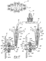
- FIG 1 is a partial side sectioned view of a staged gas turbine engine fuel system in accordance with one embodiment of the invention for supplying fuel to an annular engine combustor, which is partially shown via fuel/air injectors (so-called airblast fuel injectors).
- airblast fuel injectors are disposed in a common axial plane as shown in Figure 2, they are shown axially displaced in Figure 1 for convenience in illustrating the internal features of the injectors.
- Figure 2 is a partial top view of the embodiment of Figure 1 with the engine duct broken away to reveal the airblast fuel injectors and combustor.
- Figure 3 is an enlarged sectional view of the "fuel-pusher" airblast fuel injector of Figure 1.
- Figure 4 is an enlarged sectional view of the "fuel-puller" airblast fuel injector of Figure 1.
- FIGS 5 and 7-12 are sectional views of alternative "fuel-pusher" airblast fuel injectors usable in practicing the invention.
- the outer air shroud of these injectors is omitted in each Figure.
- Figure 6 is a sectional view of an alternative "fuel-puller" airblast fuel injector usable in practicing the invention.
- the outer air shroud is omitted from the injector in Figure 6.
- Figure 13 is a graph illustrating the relationship between the air flow velocity that would be attributable to pressure loss across the combustor and the pneumatic pressure (static air pressure) established at the fuel discharge lip of the designated fuel injectors.
- Figure 14 is a graph illustrating the relationship between the air flow velocity at various plenum air pressures (corresponding generally to compressor discharge air density) and the pressure differential generated between the fuel discharge lips of the "fuel-pusher" and “fuel-puller” injectors of Figures 8 and 4, respectively.
- Figure 15 is a graph illustrating the relationship between the air density (pressure) and the pressure differential generated between the fuel discharge lips for the "fuel-pusher" and “fuel-puller” injectors of Figure 14 obtained by taking pressure differential values from Figure 14 at a constant air velocity of 344 feet per second.
- Figure 16 is side view illustrating a fuel system in accordance with another embodiment of the invention wherein one "fuel-pusher" fuel injector is coupled in fuel flow relation to two "fuel-puller” fuel injectors.
- Figure 17 is a view similar to Figure 1 wherein radial jet fuel injectors and cooperably associated air injectors (air discharge swirlers) are substituted for the airblast fuel injectors of Figure 1.
- Figure 18 is a partial top view of the embodiment of Figure 17 with engine duct broken away to reveal the radial jet fuel injectors and associated air discharge swirlers.
- Figure 19 is an enlarged sectional view of the "fuel-pusher" radial jet fuel injector of Figure 17.
- Figure 20 is an enlarged sectional view of the "fuel-puller" radial jet fuel injector of Figure 17.
- Figure 21 is an enlarged view of the "fuel-puller" radial jet fuel injector and its associated air discharge swirler.
- Figures 22 and 23 are cross-sectional views of the inner and outer air inlet rings of the air discharge swirler (air injector) of Figure 21.
- Figure 24 is a cross-sectional view of a "fuel-puller" radial jet fuel injector in accordance with another embodiment of the invention.
- Figure 25 is a partial sectional view of the capped end of a radial jet fuel injector in accordance with still another embodiment of the invention.
- Figure 26 is a graph illustrating the relationship between the air velocity ( ⁇ P) and the pressure differential generated between fuel discharge openings of "fuel-pusher” and “fuel-puller” radial jet fuel injectors.
- a fuel/air injector system 10 in accordance with one embodiment of the invention is illustrated operatively associated relative to an annular combustor 12 of a gas turbine engine 14.
- the combustor 12 is disposed inside an engine duct 16 for receiving pressurized (superambient pressure) discharge air from an air supply plenum 23 (air supply means) which communicates with the engine compressor (not shown) located upstream of the combustor 12 in conventional manner.
- the fuel/air injector system 10 is shown including a pair of first and second fuel/air injectors 20,22 having flanges 24,26 fastened to the duct 16 and having fuel/air discharge tips 28,30 received in openings 12a,12b of the combustor wall 12d so as to communicate with the combustion chamber 32 defined therein.
- the injectors 20,22 are located in a common axial plane about the combustor 12 as shown in Figure 2. They are shown axially displaced in Figure 1 so that the internal features of the injectors may be better shown.
- the fuel/air injectors 20,22 are shown for use as secondary (or main) injectors for staging fuel supply to the combustor 12 as called for during high power (e.g., high speed) regimes of engine operation.
- a fuel distribution valve 40 fuel supply valve
- a fuel supply port PT connected by a fuel conduit 45 (shown schematically) to the injectors 20,22 to control fuel flow thereto.
- Other fuel supply ports of the fuel distribution valve 40 are likewise connected to other pairs of like fuel injectors disposed about the combustor 12 as described above.
- the fuel distribution valve 40 is connected to a source (not shown) of fuel and meters fuel to each pair of fuel/air injectors 20,22 via conduit 45 and a fuel shut-off valve 51 disposed between the conduit 45 and downstream fuel conduits 46.
- the fuel shut-off valve 51 preferably comprises an on/off check valve having a valve seat 51a and valve 51b that is biased by spring 51c to close when fuel pressure in the conduit 45 upstream of the valve is less than a selected value; e.g., when a 40 psi differential is present across the valve.
- the valve 51b is closed and seals against the seat 51a when the fuel pressure upstream of the valve drops below the selected value.
- the valve 51b may have a "soft" seat formed by a resilient (plastic) insert or a “hard” seat of suitably hard material, such as heat treatable stainless steel, to cooperate with valve seat 51a to effect sealing.
- a fuel filter element 51e is provided to remove dirt, debris, etc. from the fuel flowing through the valve 51.
- Spring 51g holds the valve seat 51a and filter element 51e in position relative to the housing 51f.
- the ends of fuel conduits 45,46 are connected to the valve housing 51f by welding, brazing or other fastening techniques.
- the fuel shut-off valve 51 may be omitted in practicing the invention.
- the fuel distribution valve 40 may be a distribution valve of the type used on the V2500 gas turbine engine sold by the Pratt & Whitney Aircraft Division of United Technologies Corporation. The distribution valve is made by the Hamilton Standard Division of United Technologies Corporation. The fuel distribution valve 40 may also comprise a distribution valve of the type described in U.S. Patent 4,614,202 and 4,590,768, the teachings of which are incorporated herein by reference.
- the injectors 20,22 are shown for use in conjunction with pilot fuel injectors 50 (only two shown in Figure 2). Although only two pilot fuel injectors are shown, it should be understood that other like pilot injectors are circumferentially disposed about the combustor 12 in a common axial plane upstream of the secondary fuel injectors 20,22.
- the pilot fuel injectors 50 may be mounted on the duct 16 in a similar manner described above for mounting the fuel injectors 20,22 so that the discharge tips 50a of the pilot injectors are received in circumferentially spaced openings in an upstream combustor wall 12e.
- the pilot fuel injectors 50 are appropriately disposed, such as at a different elevation or level, on the combustor 12 so that they receive pressurized discharge air from a plenum communicated to the engine compressor (not shown).
- the pilot fuel injectors 50 may comprise airblast fuel injectors of the type described in Helmrich U.S. Patent 3,864,186.
- the pilot fuel injectors 50 provide atomized primary fuel flow to the combustor 12 during all regimes of engine operation as is known.
- the pilot fuel injectors 50 are typically supplied with fuel via a fuel distribution valve like valve 40 described hereinabove via suitable fuel conduits.
- the first and second fuel/air injectors 20,22 are shown as comprising airblast fuel injectors wherein the pressurized discharge air (see arrows) is received from the air supply plenum 23 communicating with the engine compressor (not shown) and discharged to atomize the fuel discharging from the injector into the combustor 12 and to support combustion of the discharged fuel as a supplemental flame region in the combustor 12.
- the first and second injectors 20,22 are similar in construction with the important exception that one injector (e.g., the first injector 20) is constructed to function as a so-called "fuel-pusher” injector (i.e., having a higher static air pressure established at the fuel discharge lip) and the other injector (e.g., the second injector 22) is constructed as a so-called “fuel-puller” injector (i.e., having a lesser static air pressure established at the fuel discharge lip) in response to air discharged therefrom in order to establish a pneumatic pressure differential on the fuel residing between the respective first and second fuel discharge lips 80,82 (fuel discharge means) of sufficient magnitude in order to purge fuel in the respective injectors 20,22 as well as in fuel conduits 46 to the combustor 12 when the injectors 20,22 are rendered non-operative during the lower power regime of engine operation (e.g., during engine idle operation) or when the supply of fuel thereto is otherwise interrupted.
- fuel-pusher injector
- the second injector 22
- the first and second fuel/air injectors 20,22 comprise respective inlet fittings 60,62 to which the ends of the fuel conduits 46 are welded, brazed or otherwise fastened for supplying fuel to the injectors.
- Each fitting includes a trim orifice 64,66 which are used in conventional manner to provide generally the same fuel flow rate to each of the injectors 20,22.
- the fuel supplied to the injectors 20,22 flows through respective fuel inlet pipes 70,72 disposed in the injector housings 74,76 as shown to provide an insulating air space about each inlet pipe 70,72.
- a thermal shield 81,83 is disposed about each injector housing 74,76 to this same end.
- Each fuel discharge passage 84,86 includes an upstream and downstream portion 84a,84b and 86a,86b and a plurality of fuel swirl passages 90,92 circumferentially spaced apart between the upstream and downstream portions of each fuel discharge passage 84,86 to impart swirl to the fuel as it flows through each fuel discharge passage.
- the first and second injectors 20,22 include respective central, inner air discharge passages 100,102 integral with each injector for receiving compressor discharge air and discharging the air from respective downstream, annular inner air discharge lips 110,112 (air discharge means) communicated to the combustor 12. Similar air swirl members 114,116 are disposed in the respective air passages 100,102. Each air swirl member includes a plurality of circumferentially spaced swirl vanes 114a,116a for imparting swirl to the air flowing through the passages 100,102 before discharge from the inner air discharge lips 110,112. Tubular members 103,105 are disposed in passages 100,102 to define air spaces thereabout.
- the first and second injectors 20,22 also may include respective outer air shrouds 120,122 attached thereto and defining outer air passages 124,126 for receiving compressor discharge air and discharging the air from respective downstream, annular outer air discharge lips 130,132 communicated to the combustor 12.
- Each outer air shroud includes a plurality of circumferentially spaced swirl vanes 120a,122a for imparting swirl to the air flowing therethrough before discharge from the outer air discharge lips 130,132.
- Each outer shroud 120,122 includes an auxiliary air discharge lip 134,136 ( Figure 3 and 4) for discharging cooling air across the downstream end of the air shrouds.
- the cooling air is flowed through a plurality of circumferentially spaced, axially extending air apertures 135, 137.
- the air shrouds 120,122 may be fastened on the combustor wall 12d in lieu of the injectors 20,22.
- the first injector 20 is constructed to function as a so-called fuel-pusher injector and the second injector 22 is constructed as a so-called fuel-puller injector in response to air discharged therefrom in order to establish a pneumatic pressure differential (static air pressure differential) on the fuel residing in the injectors between the respective first and second fuel discharge lips 80,82 (fuel discharge means) of sufficient magnitude to purge the resident fuel (i.e., fuel residing in the fuel discharge passages 84,86 and other passages of the fuel injectors as well as in the fuel conduits 46) when the injectors 20,22 are rendered non-operative during the lower power regime of engine operation (e.g., during engine idle operation) or when the supply of fuel thereto is otherwise interrupted.
- a pneumatic pressure differential static air pressure differential
- the resident fuel i.e., fuel residing in the fuel discharge passages 84,86 and other passages of the fuel injectors as well as in the fuel conduits 46
- the first and second injectors 20,22 are shown including the respective inner air discharge lips 110,112 which differ in configuration in order to establish the desired pressure differential at the fuel discharge lips 80,82 as shown in Figure 13 for the inner and outer air velocities provided in the inner air passages 100,102 and air shrouds 120,122 (e.g., as a result from the pressure drop across the combustor).
- the air velocity values are set forth on the abscissa while the resulting static air pressure values at the fuel discharge lips 80 are set forth on the ordinate of Figure 13. It is apparent from Figure 13 that the measured air pressure (line labelled Fig.
- the geometric configuration of the air/fuel discharge passages/swirlers and air/fuel discharge lips were the same for injectors 20,22 with the exception that the inner air discharge lip 110 of the fuel-pusher injector 20 was machined to diverge toward the combustor 12 at a nominal 20° acute angle relative to the longitudinal center axis of the injector 20 to provide an inner air discharge lip diameter slightly larger than the diameter of the fuel discharge lip 80.
- the smaller diameter D1 of the inner air discharge lip 110 was nominally 0.280 inch diverging to a larger diameter D2 of nominally 0.320 inch.
- the inner diameter D3 of the fuel discharge lip 80 was nominally 0.300 inch. Therefore, diameter D2 of air discharge lip 110 was greater than diameter D3 of fuel discharge lip 80 of fuel-pusher injector 20.
- the inner diameter D4 of the inner air discharge lip 112 of fuel-puller injector 22 was nominally 0.280 inch, while the inner diameter D5 of the fuel discharge lip 82 thereof was nominally 0.300 inch. Diameter D4 of air discharge lip 112 was thus smaller than diameter D5 of fuel discharge lip 82 of fuel-puller injector 22.
- the widths W1,W2 of the fuel discharge passages were the same; e.g., 0.020 inch, as were their fuel lip convergence angles A1 and A2; e.g., 135°.
- the axial widths of the fuel discharge lips 80,82 were the same (0.020 inch).
- the outer air shrouds 120,122 were the same for the fuel-pusher and fuel-puller injectors 20,22; e.g., the inner diameters of lips 130,132 were nominally 0.590 inch.
- the angles A3,A4 of air lip convergence were nominally 120° for both shrouds.
- the axial space between the fuel discharge lips 80,82 and the inner air discharge lips 110,112 and between lips 80,82 and the outer air discharge lips 130,132 were also the same for injector 20,22; e.g., nominally 0.028 and 0.138 inch, respectively, for both injectors 20,22.
- the pneumatic pressure differential established at the fuel discharge lips 80,82 by cooperation of the fuel/air injectors 20,22 has been found to be sufficient to cause injector 20 to function as a fuel-pusher injector and to cause injector 22 to function as a fuel-puller injector when fuel flow is interrupted to the injectors 20,22 in the range of air flow velocities used, whereby the fuel in the injectors and in the conduits 46 is subjected to a differential pneumatic pressure that is effective to purge the fuel in the direction of arrow P in Figure 1 into the combustor 12 through the fuel discharge lip which has the lesser static pressure thereat.
- the purging of fuel in the fuel discharge passages 80,82 and in the conduits 46 occurs rapidly enough (e.g., about 3 seconds) after fuel flow is shut off by the shut-off valve 51 (in response to reduced fuel flow by the distribution valve 40) to cause the purged fuel to be ignited and combusted by the combustion flame region sustained by the fuel previously discharged from the injectors 20,22 prior to the valve 51 being closed.
- the time required for complete purging of the resident fuel may be varied by controlling the magnitude of the pressure differential established on the resident fuel.
- the gas turbine engine can be operated in a staged manner wherein the fuel injectors 20,22 are supplied fuel by the distribution valve 40 and open shut-off valve 51 as required during a high power regime of engine operation to render the injectors operative to sustain a supplemental combustion flame region in the combustor 12 for increased power.
- the distribution valve fuel 40 will be actuated to reduce fuel flow to the injectors 20,22 to an extent that causes the shut-off valve 51 to close and render the injectors 20,22 subsequently non-operative to supply supplemental fuel to the combustor 12.
- the pneumatic pressure differential is established on the fuel residing in the injectors 20,22 and conduits 46 (between the fuel discharge lips 80,82) effective to purge the resident fuel in the fuel passages 84,86 and the isolated conduits 46 into the combustor 12 rapidly enough to ignite the purged fuel by the preexisting flame region of the injectors 20,22 for combustion in the combustor. Emissions from the engine otherwise attributable to dumping of raw fuel into the combustor when the injectors 20,22 are rendered non-operative are substantially reduced. Moreover, coking of fuel that would otherwise reside in the fuel discharge passages 84,86 is substantially avoided.
- FIG. 5 and 7-12 illustrate alternative pusher airblast fuel injector constructions usable in practicing the invention wherein the outer air shroud is omitted for convenience.
- the fuel-pusher injectors have an inner air discharge lip 110 having a greater diameter than an axially proximate diameter of the fuel discharge lip 80, all other features of the discharge tips 28,30 being the same.
- the fuel-pusher injectors shown in Figures 5 and 7-12 would include an outer air shroud like that shown in Figures 3-4.
- the pneumatic pressure at the fuel discharge lip of these fuel-pusher injectors is shown in Figure 13 as determined under the same test conditions.
- Three variations of the fuel-pusher injector of Figure 10 were also tested to determine the effect of increasing the diameter D10 of the fuel discharge lip 80 by 0.0015 inch, 0.005 inch, and 0.0065 inch as designated on Figure 13.
- the increase in diameter D10 is seen to reduce the static air pressure measured at the fuel discharge lip 80.
- variation of the diameter of fuel lip 80 (relative to air lip 110) from one injector to the other may be used to establish the desired pressure differential to achieve self-sustaining purging of fuel from injectors.
- first air discharge lip 110 and first fuel discharge lip 80 is different from the relationship of the second air discharge lip 112 and the second fuel discharge lip 82 so as to provide means on the injectors cooperable with the discharged pressurized air to establish the required different pneumatic pressures (static air pressures) at the first and second fuel discharge lips.
- the relative configuration/orientation of the first fuel/air discharge lips 80,110 can be made different from the relative configuration/orientation of the second fuel/air discharge lips 82,112 to establish a selected pneumatic pressure at the first fuel discharge lip and a lesser pressure at the second fuel discharge lip to thereby establish the desired pressure differential for fuel purging.
- the fuel and air discharge lips 80,110 have the air lip 110 diverging relative to the fuel lip 80 to provide a greater air lip diameter D2 than the fuel lip diameter D3, whereas the fuel and air lips 82,112 do not have such a relationship, all other features of the discharge tips 28,30 being the same.
- the different pressures can be established by using fuel-pusher/less pusher injectors; fuel-pusher/puller injectors; or fuel-puller/less puller injectors having their fuel discharge passages in fuel flow communication.
- the magnitude of the pressure differential established between the fuel discharge lips generally depends on the geometric configuration of the fuel air/fuel discharge lips, air flow dynamics in the immediate vicinity of the air/fuel discharge lips and the plenum (supply) air pressure level.
- the air pressure or density level supplied to the first and second injectors as well as the pressure drops across the first and second fuel injector discharge tips 28,30 may be used to establish a pressure differential on the resident fuel to purge it to the combustor.
- FIG. 6 illustrates an alternative fuel-puller airblast fuel injector usable in practicing the invention where, again for the sake of convenience the outer air shroud is omitted.
- the pneumatic pressure established at the fuel discharge lip thereof is shown (line labeled Fig. 6) in Figure 13 as determined under the same test conditions.
- Figure 14 illustrates for the fuel-pusher and fuel-puller injectors 20,22 shown in Figures 8 and 4, respectively, the relationship between air flow velocity at various air plenum pressures (corresponding to compressor discharge air density) and the pneumatic pressure differential generated between their fuel discharge lips 80,82. It is apparent that the pressure differential increases with increasing air density (pressure) for the range of air velocities set forth. First and second injectors supplied with different air pressures may thus establish the desired purging pressure differential between the fuel discharge lips.
- Figure 15 illustrates for these same injectors the relationship between the air density (pressure) and the pressure differential generated between their fuel discharge lips 80,82. The data points of Figure 15 were obtained by taking pressure differential values from Figure 14 at a constant air velocity of 344 feet per second. It is apparent that the pressure differential increases with increasing air density at the constant air velocity of 344 feet per second.
- Figure 16 illustrates another embodiment of the invention where like reference numerals are used to represent like features of Figures 1-2.
- the embodiment of Figure 16 differs from that of Figures 1-2 in having one fuel-pusher injector 20 coupled in fuel flow relation to two (or more) fuel-puller injectors 22 (which may be of the same or different construction) so as to purge fuel residing between the discharge lip 80 of the fuel-pusher injector 20 and the discharge lips 82 of the fuel-puller injectors 22 by virtue of the pressure differential established on the fuel residing therein as described above.
- the fuel residing in conduits 46 is also purged as a result of the pneumatic pressure differential established.
- the direction of fuel purging is represented by arrows P.
- first and second fuel injectors comprising secondary (or main) fuel injectors of a staged fuel injector system of a gas turbine engine to supply fuel to the combustor during the high power (e.g., high speed) regime of engine operation while pilot fuel injectors provide fuel for both the lower power regime (e.g., lower idle speed) and high power engine operation.
- the invention is not so limited.
- the pilot fuel injectors 50 referred to above may be similar to the interconnected fuel injectors 20,22 so that resident fuel is purged from the pilot fuel injectors to the combustor 12 in the event of an unintentional interruption in supply of the pilot fuel thereto during operation of the engine by virtue of establishment of the aforementioned fuel pressure differential between the fuel discharge lips of the injectors 20,22.
- the interconnected fuel injectors 20,22 may be used in other instances in a fuel injector system where there is a need to purge fuel from the fuel discharge means in the event of an intentional or unintentional interruption in the supply of fuel to the injectors.
- FIG. 17-18 a fuel/air injector system in accordance with another embodiment of the invention is illustrated operatively associated with the annular combustor 12 of the gas turbine 14 previously described with respect to Figures 1-2.
- like features of Figures 1-2 are represented by like reference numerals.
- the fuel/air injector system is shown including a pair of first and second fuel injectors 220,222 having flanges 224,226 fastened to the duct 16 and having fuel discharge tips 28,30 and including respective first and second air discharge swirlers (air injectors) 227,229 of like construction having air discharge tips 228,230.
- the swirlers 227,229 are received in openings 12a,12b of the combustor wall 12d so as to communicate with the combustion chamber 32 defined therein.
- the swirlers 227,229 include flanges 227a,229a fastened to the combustor wall 12d (not the injectors 220,222) by conventional fastening means.
- the fuel injectors 220,222 are located in a common axial plane about the combustor 12 as shown in Figure 18. They are shown axially displaced in Figure 17 so that the internal features of the fuel injectors may be better shown.
- the fuel injectors 220,222 are shown for use as secondary (or main) injectors for staging fuel supply to the combustor 12 as called for during high power (e.g., high speed) regimes of engine operation.
- the fuel distribution valve 40 fuel supply valve
- the fuel distribution valve 40 is shown having a fuel supply port PT connected by a fuel conduit 45 (shown schematically) to the fuel injectors 220,222 to control fuel flow thereto.
- Other fuel supply ports of the fuel distribution valve 40 are likewise connected to other pairs of like fuel injectors disposed about the combustor 12 as described above.
- the fuel distribution valve 40 is connected to a source (not shown) of fuel and meters fuel to each pair of fuel injectors 220,222 via conduit 45 and a fuel shut-off valve 51 disposed between the conduit 45 and downstream fuel conduits 46.
- the fuel distribution valve 40 may be a distribution valve of the type described above with respect to Figures 1-2.
- the fuel injectors 220,222 are shown for use in conjunction with pilot fuel injectors 50 and air discharge swirlers (air injectors) 53 (only two of each shown in Figure 18). Although only two pilot fuel injectors and air discharge swirlers are shown, it should be understood that other like pilot injectors are circumferentially disposed about the combustor 12 in a common axial plane upstream of the secondary fuel injectors 220,222.
- the pilot fuel injectors 50 are received in the swirlers 53 which are mounted on the upstream combustor wall 12e in a similar manner described above for mounting swirlers 227,229 on downstream combustor wall 12d so that their respective fuel and air discharge tips are circumferentially spaced and communicate to the combustor 12.
- the pilot fuel injectors 50 and air swirlers 53 are appropriately disposed, such as at a different elevation or level, on the combustor 12 so that the swirlers 53 receive pressurized discharge air from a plenum communicated to the engine compressor (not shown).
- the pilot fuel injectors 50 and air swirlers 53 may comprise radial jet fuel injectors and high shear swirlers of the type in use on F100-PW229 gas turbine engine made by United Technologies Pratt & Whitney Aircraft Division.
- the pilot fuel injectors 50 and air swirlers 53 provide atomized primary fuel flow to the combustor 12 during all regimes of engine operation as is known.
- the pilot fuel injectors 50 are typically supplied with fuel via a fuel distribution valve like valve 40 described hereinabove via suitable fuel conduits.
- the first and second fuel injectors 220,222 are shown as comprising radial jet fuel injectors having an injector body 221,223 defining a central fuel discharge passage 231,233 communicated to a plurality of circumferentially spaced fuel discharge openings 235,237 located on a frusto-conical discharge tips 28,30.
- Each injector body 221,223 includes an inner body 221b,223b and outer tubular body 221c,223c fastened together at a weld or braze joint J.
- Each fuel injector includes an outer tubular cap member 241,243 disposed about the respective fuel discharge tips 28,30 thereof in spaced relation to define an annular air passage 245,247 for receiving pressurized (compressor discharge) air from plenum 23.
- the frusto-conical portion of the cap member 241,243 includes a plurality of fuel discharge openings 251,253 that are registered with the respective fuel discharge openings 235,237 so that fuel discharged from each opening 235,237 also discharges through the associated registered opening 251,253.
- the cap member 241,243 is fastened to the injector body 221,223 by brazing and/or welding.
- the tubular cap members 241,243 protect the fuel discharge ends 28,30 of the fuel injectors from possible damage during installation or assembly in the combustor 12.
- the compressor discharge air flowing through outer passages 245,247 facilitates atomization of the fuel discharged from fuel discharge openings 251,253 of the cap members 241,243.
- the first and second fuel injectors 220,222 are of like construction with the important exception that one fuel injector (e.g., the first fuel injector 220) is constructed to function as a so-called "fuel-pusher" fuel injector and the other fuel injector (e.g., the second fuel injector 222) is constructed to function as a so-called “fuel-puller” fuel injector in cooperation with air discharged from air injectors 227,229 in order to establish a pneumatic pressure differential on the fuel residing between respective first and second fuel discharge openings 251,253 (fuel discharge means) of sufficient magnitude in order to purge fuel in the respective fuel injectors 220,222 as well as in fuel conduits 46 to the combustor 12 when the injectors 220,222 are rendered non-operative during the lower power regime of engine operation (e.g., during engine idle operation) or when the supply of fuel thereto is otherwise interrupted.
- the arrows in Figures 17 and 19-20 illustrate the direction of fuel purging as a result of the pressure differential established
- the first and second fuel injectors 220,222 comprise respective inlet fittings 260,262 to which the ends of the fuel conduits 46 are welded, brazed or otherwise fastened for supplying fuel to the injectors.
- Each fitting includes a trim orifice 264,266 which are used in conventional manner to provide generally the same fuel flow rate to each of the injectors 220,222.
- the fuel supplied to the injectors 220,222 flows through respective fuel inlet pipes 270,272 disposed in the injector bodies 221,223 as shown to provide an insulating air space about each inlet pipe 270,272.
- a thermal shield 281,283 is disposed about each injector bodies 221,223 to this same end.
- the fuel flows from the inlet pipes 270,272 through the respective fuel discharge passages 231,233 in the respective injector bodies 221,223 for discharge from the respective downstream annular array of circumferentially spaced fuel discharge openings 235,237 communicated to the combustor 12 via the swirlers 227,229.
- the first and second air discharge swirlers (air injectors) 227,229 are cooperatively associated or disposed to the respective fuel injectors 220,222.
- the fuel discharge ends 28,30 of the fuel injectors are received in respective central upstream openings in air swirlers 227,229 as shown such that the cap fuel discharge openings 251,253 are located in the inner air discharge passages 300,302 of the air swirlers 227,229 as shown in Figure 17.
- the air discharge swirlers (air injectors) 227,229 include the respective central, inner air discharge passages 300,302 for discharging pressurized air from respective downstream, annular inner air discharge lips 310,312 (air discharge means) communicated to the combustor 12.
- the air swirlers 227,229 also include outer, annular air discharge passages 320,322 for discharging pressurized air from respective downstream, annular outer air discharge lips 324,325.
- the inner and outer air discharge passages 300,320 of swirler 227 receive compressor discharge air from plenum 23 via air swirler rings 330,332.
- Each air swirl ring 330,332 includes a plurality of circumferentially spaced swirl passages 330a,332a ( Figures 22-23) for imparting swirl to the air flowing therethrough from the plenum 23 to the inner and outer air discharge passages 300,320.
- the inner and outer air discharge passages 302,322 of swirler 229 receive compressor discharge in the same way since the swirlers 227,229 are identical in construction.
- the swirl passages 330a,332a of each swirler 227,229 provide an aggregate effective air flow area of about 0.40 in2 for each swirler.
- the first fuel injector 220 is constructed to function as a so-called fuel-pusher fuel injector and the second fuel injector 222 is constructed as a so-called fuel-puller fuel injector in response to air discharged from air injectors 227,229 in order to establish a pneumatic pressure differential (static air pressure differential) on the fuel residing in the fuel injectors between the respective first and second fuel discharge openings 251,253 (fuel discharge means) of sufficient magnitude to purge the resident fuel (i.e., fuel residing in the fuel discharge passages 231,233 as well as in the fuel conduits 46) when the injectors 220,222 are rendered non-operative during the lower power regime of engine operation (e.g., during engine idle operation) or when the supply of fuel thereto is otherwise interrupted.
- a pneumatic pressure differential static air pressure differential
- the resident fuel i.e., fuel residing in the fuel discharge passages 231,233 as well as in the fuel conduits 46
- the first and second fuel injectors 220,222 are shown including the respective cap fuel discharge opening 251,253 which differ in size (i.e., diameter) in order to establish the desired pressure differential thereat as shown in Figure 26 for the inner and outer air velocities provided in the inner air passages 300,302 and outer air discharge passages 320,322 (e.g., as a result from the pressure drop across the combustor).
- the air-pressure ⁇ P values are set forth on the abscissa of Figure 26 while the resulting static air pressure values at the fuel discharge openings 251,253 are set forth on the ordinate of Figure 26. It is apparent from Figure 26 that the measured air pressure (line designated D- Fig. 19 and C- Fig.
- the pneumatic pressures were measured at sea level pressure using a U-tube water manometer with no fuel flowing through the fuel passages/openings of the injectors.
- the geometric configuration of the fuel discharge passages 231,233 and fuel discharge openings 235,237 were the same for injectors 220,222.
- the passages 231,233 and openings 235,237 were 0.180 and 0.026 inch in nominal diameter, respectively.
- the nominal diameter of fuel discharge openings 251 was smaller than the nominal diameter of fuel discharge openings 253 (e.g., 0.052 inch versus 0.079 inch).
- the air discharge swirlers (air injectors) 227,229 are identical in construction for fuel injectors 220,222 for the pneumatic pressures measured and shown on Figure 26.
- the pneumatic pressure differential established at the fuel discharge openings 251,253 is sufficient to cause injector 220 to function as a fuel-pusher injector and to cause injector 222 to function as a fuel-puller injector when fuel flow is interrupted to the injectors 220,222 in the range of air flow velocities provided by swirlers 227,229, whereby the fuel in the fuel injectors and in the conduits 46 is subjected to a differential pneumatic pressure that is effective to purge the fuel in the direction of arrow P in Figure 17 into the combustor 12 through the fuel discharge openings 253 which has the lesser static pressure thereat.
- the purging of fuel in the fuel discharge passages 231,233 and in the conduits 46 occurs rapidly enough after fuel flow is shut off by the shut-off valve 51 (in response to reduced fuel flow by the distribution valve 40) to cause the purged fuel to be ignited and combusted by the combustion flame region sustained by the fuel previously discharged from the fuel injectors 220,222 and air discharge swirlers (air injectors) 227,229 prior to the valve 51 being closed.
- the time required for complete purging of the resident fuel may be varied by controlling the magnitude of the pressure differential established on the resident fuel.
- the gas turbine engine can be operated in a staged manner wherein the fuel injectors 220,222 are supplied fuel by the distribution valve 40 and open shut-off valve 51 as required during a high power regime of engine operation to render the injectors operative to sustain a supplemental combustion flame region in the combustor 12 for increased power.
- the distribution valve fuel 40 will be actuated to reduce fuel flow to the injectors 220,222 to an extent that causes the shut-off valve 51 to close and render the injectors 220,222 subsequently non-operative to supply supplemental fuel to the combustor 12.
- the pneumatic pressure differential is established by fuel and air injectors 220,222 and 227,229 on the fuel residing in the injectors 220,222 and conduits 46 (between the fuel discharge openings 251,253) effective to purge the resident fuel in the fuel passages 231,233 and the isolated conduits 46 into the combustor 12 rapidly enough to ignite the purged fuel by the preexisting flame region for combustion in the combustor. Emissions from the engine otherwise attributable to dumping of raw fuel into the combustor when the injectors 220,222 are rendered non-operative are substantially reduced. Moreover, coking of fuel that would otherwise reside in the fuel discharge passages 231,233 is substantially avoided.
- Figure 24 illustrate an alternative puller fuel injector construction usable in practicing the invention.
- a sleeve 355 is used that includes an annular, upstream end wall 355a to prevent plenum air from flowing therepast and a shortened end 355b that leaves fuel discharge openings 237 of the fuel injector 222 exposed.
- the pneumatic pressure measured at the fuel discharge openings 237 of this fuel-puller injector is shown in Figure 26 (see line designated A-Fig. 26) as determined under the same test conditions described above. It is apparent that a negative pressure is present at the fuel discharge openings 237.
- the different pressures needed to purge the fuel injectors 220,222 can be established by using fuel-pusher/less pusher injectors; fuel-pusher/puller injectors; or fuel-puller/less puller injectors having their fuel discharge passages in fuel flow communication.
- the magnitude of the pressure differential established between the fuel discharge openings 251,253 for the embodiment of Figs. 17-20 generally depends on the geometric size of these openings, air flow dynamics in the immediate vicinity of these openings and the plenum (supply) air pressure level.
- injector 220 of Fig. 17 and injector 222 of Fig. 24 are coupled or connected in the manner shown in Figure 17. That is, the magnitude of the pressure differential established between the fuel discharge openings 251 (Figs. 17,19), and 237 (Fig. 24) depends on the aforementioned factors.
- different air discharge characteristics from the air swirlers (air injectors) 227,229 relative to the respective first and second injectors 220,222 may be used to establish a pressure differential on the resident fuel to purge it to the combustor.
- the line designated B-Fig. 26 represents the static pressure measured at fuel discharge openings 237 of the fuel injector shown in Figure 24 under the same test conditions with the exception that a smaller air swirler (not shown) having an effective airflow area of 0.130 in2 was used with the fuel injector rather than the air swirler 229 shown and described with respect to Figures 17, 21-23 having an effective air flow area of 0.40 in2.
- the smaller air swirler is similar in construction to air swirler 229 but provides an aggregate effective air flow area of only 0.130 in2 through the inner and outer swirl passages that are similar to swirl passages 330a,332 a of Figs. 22-23.
- use of the smaller effective air flow area swirler with the fuel injector 222 of Figure 24 provides a positive static pressure at the fuel discharge openings 237. This contrasts to the negative static pressure measured at the fuel discharge openings 237 of a like fuel injector 222 (Fig. 24) used with the larger effective air flow swirler (Figs. 17, 21-23).
- the fuel injector of Figure 24 functions as a "puller” fuel injector when used with the larger effective area air swirler 229 but functions as a "pusher” fuel injector when used with a smaller effective air flow area swirler.
- Figure 25 illustrates another embodiment of the invention where the tubular cap members 241,243 are replaced with an alternative cap member 261 that includes an outer peripheral lip 263 that is fastened to the annular wall 331 of the swirler 227 (or 229), Fig. 21.
- the wall 331 is spaced from the injector body 221 (or 223) to form the air passage 245(247) for conducting pressurized air.
- first and second fuel injectors comprising secondary (or main) fuel injectors of a staged fuel injector system of a gas turbine engine to supply fuel to the combustor during the high power (e.g., high speed) regime of engine operation while pilot fuel injectors provide fuel for both the lower power regime (e.g., lower idle speed) and high power engine operation.
- the invention is not so limited.
- the pilot fuel injectors referred to above may be similar to the interconnected fuel injectors 20,22 (220,222) so that resident fuel is purged from the pilot fuel injectors to the combustor 12 in the event of an unintentional interruption in supply of the pilot fuel thereto during operation of the engine by virtue of establishment of the aforementioned fuel pressure differential between the fuel discharge lips of the injectors.
- the interconnected fuel injectors 20,22 (220,222) may be used in other instances in a fuel injector system where there is a need to purge fuel from the fuel discharge means in the event of an intentional or unintentional interruption in the supply of fuel to the injectors.
- An injector system for a combustor of a gas turbine engine comprising first and second fuel injector means including respective first and second fuel discharge means, said first and second fuel discharge means being in fuel flow communication to one another and including respective first and second fuel discharge lips for discharging the fuel to the combustor, and first and second air injector means cooperably associated with the respective first and second fuel injector means and including first and second air discharge lips for discharging pressurized air to the combustor, wherein the relationship of the first fuel discharge lip and first air discharge lip is different from the relationship of the second fuel discharge lip and the second air discharge lip so as to establish different pneumatic pressures at the first and second fuel discharge lips in response to discharge of the pressurized air from the first and second air discharge lips such that, in the event the supply of fuel to the first and second fuel discharge means is interrupted during operation of the engine, the fuel residing in the fuel injector means between the first and second fuel discharge lips is subjecte
- Such a system advantageously includes conduit means connected between the first and second fuel discharge means for communicating said first and second fuel discharge means in fuel flow communication.
- fuel shut-off valve means may be operatively disposed between the conduit means and a fuel supply means to isolate the conduit means from the fuel supply means in the event the fuel supply is interrupted such that said pressure differential purges into the combustor fuel residing in the conduit means downstream of said shut-off valve means.
- first and second fuel injector means including respective first and second fuel discharge means, said first and second fuel discharge means being in fuel flow communication to one another and including respective first and second annular arrays of circumferentially spaced fuel discharge openings for discharging the fuel to the combustor
- first and second air injector means cooperably associated with the respective first and second fuel injector means and including respective first and second air discharge swirlers disposed radially outward of the respective first and second annular arrays of fuel discharge openings and each having a plurality of circumferentially spaced air discharge apertures for discharging pressurized air to the combustor
- the size of the first fuel discharge openings is different from the size of the second fuel discharge openings so as to establish different pneumatic pressures at the first and second fuel discharge openings in response to discharge of the pressurized air from the first and second air discharge swirlers such that, in the event the supply of fuel to the first and second fuel discharge
- a further improved such system includes conduit means connected between the first and second fuel discharge means for communicating said first and second fuel discharge means in fuel flow communication.
- fuel shut-off valve means is operatively disposed between the conduit means and a fuel supply means to isolate the conduit means from the fuel supply means in the event the fuel supply is interrupted such that said pressure differential purges into the combustor fuel residing in the conduit means downstream of said shut-off valve means.
- first and second fuel/air injector means including respective first and second fuel discharge means in fuel flow communication to one another and having respective first and second fuel discharge lips for discharging the fuel to the combustor, and including respective first and second air discharge means having respective first and second air discharge lips for discharging pressurized air to the combustor, wherein the relationship of the said first fuel discharge lip and first air discharge lip is different from the relationship of the second fuel discharge lip and the second air discharge lip so as to establish different pneumatic pressures at the first and second fuel discharge lips such that, in the event the supply of fuel to the first and second fuel discharge means is interrupted during operation of the engine, the fuel residing in the fuel/air injector means between the first and second fuel discharge lips is subjected to a pressure differential effective to purge the resident fuel into the combustor for combustion therein.
- Subject matter of the present invention is also an injector system for a combustor of a gas turbine engine, comprising a plurality of fuel injector means including respective fuel discharge means in fuel flow communication to one another and having respective fuel discharge lips for discharging the fuel to the combustor, and including a plurality of air injector means each cooperably associated with a respective fuel injector means and having respective air discharge lips for discharging pressurized air to the combustor, wherein the relationship of the fuel discharge lip and air discharge lip of one set of said fuel injector means and associated air injector means is different from the relationship of the fuel discharge lip and associated air discharge lip of the other sets of said fuel injector means and associated air injector means so as to establish a pneumatic pressure at said one fuel discharge lip different from the pneumatic pressures established at said other fuel discharge lips such that, in the event the supply of fuel to the fuel discharge means is interrupted during operation of the engine, the fuel residing in the fuel injector means between said one fuel discharge lip and said other fuel discharge lips is subjected to a pressure differential
- Subject of the present invention is also an injector system for a combustor of a gas turbine engine, comprising first and second fuel injector means rendered operative during a high power regime of engine operation as a result of fuel being supplied thereto from a fuel supply means for discharge to the combustor to sustain a flame region therein and rendered non-operative during a lower power regime of engine operation as a result of fuel not being supplied thereto from the fuel supply means, said first and second fuel injector means including respective first and second fuel discharge means for receiving fuel from the fuel supply means, said first and second fuel discharge means being in fuel flow relation and having respective first and second fuel discharge lips for discharging fuel to the combustor, and comprising first and second air injector means cooperably associated with the respective first and second fuel injector means for receiving pressurized air from air supply means during both high and lower power regimes of engine operation and having respective first and second air discharge lips for discharging pressurized air to the combustor for sustaining said flame region, wherein the relationship of the first fuel discharge lip and first air
- the invention can also be seen in an injector system for a combustor of a gas turbine engine, comprising first and second fuel injector means including respective first and second fuel discharge means, said first and second fuel discharge means being in fuel flow communication to one another and communicated to the combustor for discharging the fuel thereto, and first and second air injector means cooperably associated with the respective first and second fuel injector means and including respective first and second air discharge means communicated to the combustor for discharging pressurized air thereto, said first fuel discharge means and associated first air discharge means having a relationship different from said second fuel discharge means and associated second air discharge means so as to establish different pneumatic pressures at the first and second fuel discharge means such that, in the event the supply of fuel to the first and second fuel discharge means is interrupted during operation of the engine, the fuel residing in the fuel injector means between the first and second fuel discharge means is subjected to a pressure differential effective to purge the resident fuel into the combustor for combustion therein.
- Subject matter of the present invention is also an injector system for a combustor of a gas turbine engine, comprising first and second fuel injector means including respective first and second fuel discharge means, said first and second fuel discharge means being in fuel flow communication to one another and communicated to the combustor for discharging the fuel thereto, and first and second air injector means cooperably associated with the respective first and second fuel injector means and including respective first and second air discharge means communicated to the combustor for discharging pressurized air thereto, said first fuel discharge means being different in size from said second fuel discharge means to establish different pneumatic pressures at the first and second fuel discharge means in response to discharge of pressurized air from said first and second air discharge means such that, in the event the supply of fuel to the first and second fuel discharge means is interrupted during operation of the engine, the fuel residing in the fuel injector means between the first and second fuel discharge means is subjected to a pressure differential effective to purge the resident fuel into the combustor for combustion therein.
- the present invention can also be seen in an injector system for a combustor of a gas turbine engine, comprising first and second fuel injector means including respective first and second fuel discharge means, said first and second fuel discharge means being in fuel flow communication to one another and communicated to the combustor for discharging the fuel thereto, and first and second air injector means cooperably associated with the respective first and second fuel injector means and including respective first and second air discharge means communicated to the combustor for discharging pressurized air thereto, said first air discharge means and said second air discharge means being different in size so as to establish different pneumatic pressures at the first and second fuel discharge means such that, in the event the supply of fuel to the first and second fuel discharge means is interrupted during operation of the engine, the fuel residing in the fuel injector means between the first and second fuel discharge means is subjected to a pressure differential effective to purge the resident fuel into the combustor for combustion therein.
- the present invention is to be seen in an injector system for a combustor of a gas turbine engine, comprising first and second fuel injector means including respective first and second fuel discharge means, said first and second fuel discharge means being in fuel flow communication to one another and communicated to the combustor for discharging the fuel thereto, and first and second air injector means cooperably associated with the respective first and second fuel injector means and including respective first and second air discharge means communicated to the combustor for discharging pressurized air thereto, said first air discharge means and said second air discharge means having different air discharge characteristics effective to establish different pneumatic pressures at the first and second fuel discharge means such that, in the event the supply of fuel to the first and second fuel discharge means is interrupted during operation of the engine, the fuel residing in the fuel injector means between the first and second fuel discharge means is subjected to a pressure differential effective to purge the resident fuel into the combustor for combustion therein.
- subject matter of the present invention is an injector system for a combustor of a gas turbine engine, comprising first and second fuel injector means including respective first and second fuel discharge means, said first and second fuel discharge means being in fuel flow communication to one another and communicated to the combustor for discharging the fuel thereto, and first and second air injector means cooperably associated with the respective first and second fuel injector means and including respective first and second air discharge means communicated to the combustor for discharging pressurized air thereto, said first air discharge means and said second air discharge means having different air flow areas effective to establish different pneumatic pressures at the first and second fuel discharge means such that, in the event the supply of fuel to the first and second fuel discharge means is interrupted during operation of the engine, the fuel residing in the fuel injector means between the first and second fuel discharge means is subjected to a pressure differential effective to purge the resident fuel into the combustor for combustion therein.
Landscapes
- Engineering & Computer Science (AREA)
- Chemical & Material Sciences (AREA)
- Combustion & Propulsion (AREA)
- Mechanical Engineering (AREA)
- General Engineering & Computer Science (AREA)
- Fuel-Injection Apparatus (AREA)
Priority Applications (5)
| Application Number | Priority Date | Filing Date | Title |
|---|---|---|---|
| US07/885,499 US5277023A (en) | 1991-10-07 | 1992-05-19 | Self-sustaining fuel purging fuel injection system |
| EP93114015A EP0646706B1 (fr) | 1992-05-19 | 1993-09-02 | Système d'injection de combustible avec purge auto-entretenue |
| DE1993627241 DE69327241T2 (de) | 1993-09-02 | 1993-09-02 | Brennstoffeinspritzsystem mit selbstunterhaltender Reinigung |
| US08/119,431 US5417054A (en) | 1992-05-19 | 1993-09-10 | Fuel purging fuel injector |
| US08/159,949 US5329760A (en) | 1991-10-07 | 1993-11-30 | Self-sustaining fuel purging fuel injection system |
Applications Claiming Priority (4)
| Application Number | Priority Date | Filing Date | Title |
|---|---|---|---|
| US07/885,499 US5277023A (en) | 1991-10-07 | 1992-05-19 | Self-sustaining fuel purging fuel injection system |
| EP93114015A EP0646706B1 (fr) | 1992-05-19 | 1993-09-02 | Système d'injection de combustible avec purge auto-entretenue |
| US08/119,431 US5417054A (en) | 1992-05-19 | 1993-09-10 | Fuel purging fuel injector |
| US08/159,949 US5329760A (en) | 1991-10-07 | 1993-11-30 | Self-sustaining fuel purging fuel injection system |
Publications (2)
| Publication Number | Publication Date |
|---|---|
| EP0646706A1 true EP0646706A1 (fr) | 1995-04-05 |
| EP0646706B1 EP0646706B1 (fr) | 1999-12-08 |
Family
ID=27442587
Family Applications (1)
| Application Number | Title | Priority Date | Filing Date |
|---|---|---|---|
| EP93114015A Expired - Lifetime EP0646706B1 (fr) | 1991-10-07 | 1993-09-02 | Système d'injection de combustible avec purge auto-entretenue |
Country Status (1)
| Country | Link |
|---|---|
| EP (1) | EP0646706B1 (fr) |
Cited By (3)
| Publication number | Priority date | Publication date | Assignee | Title |
|---|---|---|---|---|
| EP0939275A3 (fr) * | 1997-12-30 | 1999-09-29 | United Technologies Corporation | Injecteur de combustible et dispositif de guidage de l'injecteur pour une turbine à gaz |
| US6412272B1 (en) | 1998-12-29 | 2002-07-02 | United Technologies Corporation | Fuel nozzle guide for gas turbine engine and method of assembly/disassembly |
| EP1591720A1 (fr) | 2004-04-30 | 2005-11-02 | United Technologies Corporation | Injecteur de carburant assisté par air pour chambre de combustion |
Citations (2)
| Publication number | Priority date | Publication date | Assignee | Title |
|---|---|---|---|---|
| GB2021254A (en) * | 1978-04-18 | 1979-11-28 | Lucas Industries Ltd | Fuel injector |
| WO1990005877A1 (fr) * | 1988-11-17 | 1990-05-31 | Sundstrand Corporation | Systeme d'injection de carburant pour moteur a turbine |
-
1993
- 1993-09-02 EP EP93114015A patent/EP0646706B1/fr not_active Expired - Lifetime
Patent Citations (2)
| Publication number | Priority date | Publication date | Assignee | Title |
|---|---|---|---|---|
| GB2021254A (en) * | 1978-04-18 | 1979-11-28 | Lucas Industries Ltd | Fuel injector |
| WO1990005877A1 (fr) * | 1988-11-17 | 1990-05-31 | Sundstrand Corporation | Systeme d'injection de carburant pour moteur a turbine |
Cited By (4)
| Publication number | Priority date | Publication date | Assignee | Title |
|---|---|---|---|---|
| EP0939275A3 (fr) * | 1997-12-30 | 1999-09-29 | United Technologies Corporation | Injecteur de combustible et dispositif de guidage de l'injecteur pour une turbine à gaz |
| US6412272B1 (en) | 1998-12-29 | 2002-07-02 | United Technologies Corporation | Fuel nozzle guide for gas turbine engine and method of assembly/disassembly |
| EP1591720A1 (fr) | 2004-04-30 | 2005-11-02 | United Technologies Corporation | Injecteur de carburant assisté par air pour chambre de combustion |
| US7251940B2 (en) | 2004-04-30 | 2007-08-07 | United Technologies Corporation | Air assist fuel injector for a combustor |
Also Published As
| Publication number | Publication date |
|---|---|
| EP0646706B1 (fr) | 1999-12-08 |
Similar Documents
| Publication | Publication Date | Title |
|---|---|---|
| US5277023A (en) | Self-sustaining fuel purging fuel injection system | |
| US5329760A (en) | Self-sustaining fuel purging fuel injection system | |
| US5243816A (en) | Self purging fuel injector | |
| EP1069377B1 (fr) | Dispositif de purge de combustible pour injecteur de combustible | |
| EP0724115B1 (fr) | Procédé de purge pour injecteur de turbine à gaz | |
| KR100372907B1 (ko) | 터빈의확산작동모드와예비혼합작동모드사이에서연료를단계적으로제어하는가스터빈용연소기작동방법 | |
| EP1750056B1 (fr) | Injecteur de carburant | |
| EP2554905B1 (fr) | Ensembles et appareil se rapportant à l'intégration de l'injection pauvre tardive des moteurs de turbine à combustion | |
| US6073436A (en) | Fuel injector with purge passage | |
| US20170276365A1 (en) | Combustion System with Panel Fuel Injector | |
| CA2104523A1 (fr) | Ajutage d'une turbine a gaz | |
| GB2131154A (en) | Fuel injector assembly with water or auxiliary fuel capability | |
| CN101354141B (zh) | 用于燃气涡轮发动机的燃料喷嘴及其制造方法 | |
| EP2212622A2 (fr) | Injecteur de carburant pour turbine à gaz équipé d'un tube de liquide pilote amovible | |
| CN113864065B (zh) | 点燃涡轮机中的液体燃料的方法 | |
| US4938417A (en) | Airblast fuel injector with tubular metering valve | |
| US4562698A (en) | Variable area means for air systems of air blast type fuel nozzle assemblies | |
| EP3428537B1 (fr) | Chambre de combustion de turbomachine comprnant une connexion intégrée de buse à combustible | |
| US11002196B2 (en) | Combustion chamber comprising two types of injectors in which the sealing members have a different opening threshold | |
| EP0646706B1 (fr) | Système d'injection de combustible avec purge auto-entretenue | |
| CA1188111A (fr) | Adduction d'air variable pour moteurs a combustion | |
| EP4015910A1 (fr) | Dispositif d'allumage continu à montage interne et à orientation axiale : buse amovible | |
| EP0646707B1 (fr) | Injecteur de carburant autopurgeur pour une chambre de combustion de turbine à gaz | |
| US20240263786A1 (en) | Central air passage with radial fuel distributor | |
| CN114483321B (zh) | 具有一体化头端的集成燃烧喷嘴 |
Legal Events
| Date | Code | Title | Description |
|---|---|---|---|
| PUAI | Public reference made under article 153(3) epc to a published international application that has entered the european phase |
Free format text: ORIGINAL CODE: 0009012 |
|
| AK | Designated contracting states |
Kind code of ref document: A1 Designated state(s): DE FR GB |
|
| 17P | Request for examination filed |
Effective date: 19950906 |
|
| 17Q | First examination report despatched |
Effective date: 19961022 |
|
| GRAG | Despatch of communication of intention to grant |
Free format text: ORIGINAL CODE: EPIDOS AGRA |
|
| GRAG | Despatch of communication of intention to grant |
Free format text: ORIGINAL CODE: EPIDOS AGRA |
|
| GRAH | Despatch of communication of intention to grant a patent |
Free format text: ORIGINAL CODE: EPIDOS IGRA |
|
| GRAH | Despatch of communication of intention to grant a patent |
Free format text: ORIGINAL CODE: EPIDOS IGRA |
|
| GRAA | (expected) grant |
Free format text: ORIGINAL CODE: 0009210 |
|
| AK | Designated contracting states |
Kind code of ref document: B1 Designated state(s): DE FR GB |
|
| REF | Corresponds to: |
Ref document number: 69327241 Country of ref document: DE Date of ref document: 20000113 |
|
| ET | Fr: translation filed | ||
| PLBE | No opposition filed within time limit |
Free format text: ORIGINAL CODE: 0009261 |
|
| STAA | Information on the status of an ep patent application or granted ep patent |
Free format text: STATUS: NO OPPOSITION FILED WITHIN TIME LIMIT |
|
| 26N | No opposition filed | ||
| REG | Reference to a national code |
Ref country code: GB Ref legal event code: IF02 |
|
| PGFP | Annual fee paid to national office [announced via postgrant information from national office to epo] |
Ref country code: FR Payment date: 20060918 Year of fee payment: 14 |
|
| PGFP | Annual fee paid to national office [announced via postgrant information from national office to epo] |
Ref country code: DE Payment date: 20061031 Year of fee payment: 14 |
|
| PG25 | Lapsed in a contracting state [announced via postgrant information from national office to epo] |
Ref country code: DE Free format text: LAPSE BECAUSE OF NON-PAYMENT OF DUE FEES Effective date: 20080401 |
|
| REG | Reference to a national code |
Ref country code: FR Ref legal event code: ST Effective date: 20080531 |
|
| PG25 | Lapsed in a contracting state [announced via postgrant information from national office to epo] |
Ref country code: FR Free format text: LAPSE BECAUSE OF NON-PAYMENT OF DUE FEES Effective date: 20071001 |
|
| PGFP | Annual fee paid to national office [announced via postgrant information from national office to epo] |
Ref country code: GB Payment date: 20120925 Year of fee payment: 20 |
|
| REG | Reference to a national code |
Ref country code: GB Ref legal event code: PE20 Expiry date: 20130901 |
|
| PG25 | Lapsed in a contracting state [announced via postgrant information from national office to epo] |
Ref country code: GB Free format text: LAPSE BECAUSE OF EXPIRATION OF PROTECTION Effective date: 20130901 |