EP0646777B1 - Radlastsensor mit piezoelektrischem Messelement sowie Verfahren zum Herstellen des Radlastsensors - Google Patents
Radlastsensor mit piezoelektrischem Messelement sowie Verfahren zum Herstellen des Radlastsensors Download PDFInfo
- Publication number
- EP0646777B1 EP0646777B1 EP94113504A EP94113504A EP0646777B1 EP 0646777 B1 EP0646777 B1 EP 0646777B1 EP 94113504 A EP94113504 A EP 94113504A EP 94113504 A EP94113504 A EP 94113504A EP 0646777 B1 EP0646777 B1 EP 0646777B1
- Authority
- EP
- European Patent Office
- Prior art keywords
- measuring element
- piezoelectric measuring
- wheel load
- load sensor
- hollow conductor
- Prior art date
- Legal status (The legal status is an assumption and is not a legal conclusion. Google has not performed a legal analysis and makes no representation as to the accuracy of the status listed.)
- Expired - Lifetime
Links
- 238000000034 method Methods 0.000 title claims description 11
- 239000004020 conductor Substances 0.000 claims abstract description 24
- 238000005266 casting Methods 0.000 claims description 4
- 238000009434 installation Methods 0.000 claims description 4
- 239000002184 metal Substances 0.000 claims description 2
- 238000005259 measurement Methods 0.000 abstract description 11
- 230000005540 biological transmission Effects 0.000 abstract description 4
- 238000001514 detection method Methods 0.000 abstract description 3
- 150000001875 compounds Chemical class 0.000 description 10
- 238000004382 potting Methods 0.000 description 10
- 238000004519 manufacturing process Methods 0.000 description 6
- SZUVGFMDDVSKSI-WIFOCOSTSA-N (1s,2s,3s,5r)-1-(carboxymethyl)-3,5-bis[(4-phenoxyphenyl)methyl-propylcarbamoyl]cyclopentane-1,2-dicarboxylic acid Chemical compound O=C([C@@H]1[C@@H]([C@](CC(O)=O)([C@H](C(=O)N(CCC)CC=2C=CC(OC=3C=CC=CC=3)=CC=2)C1)C(O)=O)C(O)=O)N(CCC)CC(C=C1)=CC=C1OC1=CC=CC=C1 SZUVGFMDDVSKSI-WIFOCOSTSA-N 0.000 description 5
- 229940126543 compound 14 Drugs 0.000 description 5
- 238000013461 design Methods 0.000 description 3
- 238000007789 sealing Methods 0.000 description 3
- 239000002131 composite material Substances 0.000 description 2
- 238000010276 construction Methods 0.000 description 2
- 238000011161 development Methods 0.000 description 2
- 238000012549 training Methods 0.000 description 2
- 238000004873 anchoring Methods 0.000 description 1
- 239000003990 capacitor Substances 0.000 description 1
- 239000002800 charge carrier Substances 0.000 description 1
- 230000001419 dependent effect Effects 0.000 description 1
- 238000011982 device technology Methods 0.000 description 1
- 230000000694 effects Effects 0.000 description 1
- 238000005516 engineering process Methods 0.000 description 1
- 239000003822 epoxy resin Substances 0.000 description 1
- 239000011888 foil Substances 0.000 description 1
- 230000035515 penetration Effects 0.000 description 1
- 230000010287 polarization Effects 0.000 description 1
- 229920000647 polyepoxide Polymers 0.000 description 1
- 229920006126 semicrystalline polymer Polymers 0.000 description 1
- 238000000926 separation method Methods 0.000 description 1
- 238000003860 storage Methods 0.000 description 1
- 238000012546 transfer Methods 0.000 description 1
Images
Classifications
-
- G—PHYSICS
- G01—MEASURING; TESTING
- G01G—WEIGHING
- G01G3/00—Weighing apparatus characterised by the use of elastically-deformable members, e.g. spring balances
- G01G3/12—Weighing apparatus characterised by the use of elastically-deformable members, e.g. spring balances wherein the weighing element is in the form of a solid body stressed by pressure or tension during weighing
- G01G3/13—Weighing apparatus characterised by the use of elastically-deformable members, e.g. spring balances wherein the weighing element is in the form of a solid body stressed by pressure or tension during weighing having piezoelectric or piezoresistive properties
-
- G—PHYSICS
- G01—MEASURING; TESTING
- G01G—WEIGHING
- G01G19/00—Weighing apparatus or methods adapted for special purposes not provided for in the preceding groups
- G01G19/02—Weighing apparatus or methods adapted for special purposes not provided for in the preceding groups for weighing wheeled or rolling bodies, e.g. vehicles
- G01G19/022—Weighing apparatus or methods adapted for special purposes not provided for in the preceding groups for weighing wheeled or rolling bodies, e.g. vehicles for weighing wheeled or rolling bodies in motion
- G01G19/024—Weighing apparatus or methods adapted for special purposes not provided for in the preceding groups for weighing wheeled or rolling bodies, e.g. vehicles for weighing wheeled or rolling bodies in motion using electrical weight-sensitive devices
Definitions
- the invention relates to a casting compound positioned wheel load sensor for installation in a recess in a road surface or the like, with a piezoelectric designed as a cable Measuring element that serves as an internal electrode Encloses the conductor and at least one waveguide enclosed as an outer electrode and in the covering of one Lane can be installed.
- the invention further relates to a method of making such Wheel load sensor.
- Wheel load sensors of this type and methods for their production are already known and about in the EP-0 231 669.
- piezoelectric measuring elements are usually round piezoelectric cables or strip-shaped piezoelectric films are used. A such cable is known from FR-2 596 568.
- these cables include an inner conductor and are in turn enclosed by a waveguide and this sensor arrangement is open on one side Profile tube added and embedded in potting compound.
- the invention is therefore based on the object in Construction and manufacture simple wheel load sensor as well to create a method for its production, in which the Horizontal components that interfere with the measurement accuracy Measurement can be minimized and thereby the piezoelectric Measuring element precisely the vertical pressure components of the gives corresponding electrical signals to the respective wheel load.
- This task is in terms of device technology solved in that in the wheel load sensor after Preamble of claim 1 to the level of the road surface approximately parallel wall sections of the piezoelectric measuring element under predetermined Compressive stress between the adjacent wall areas of the waveguide forming the outer electrode and the remaining wall sections of the piezoelectric measuring element spaced in the waveguide from its other walls are included.
- the piezoelectric measuring element used can it is flattened when the waveguide is deformed, but originally act round cable. It a flat cable can also be used from the outset whose flat sides are then between the adjacent ones Wall areas of the flattened waveguide clamped are. In view of this tension, the Wheel load sensor extremely sensitive and it is an installation possible under the flat track surface.
- a wheel load sensor system that can be installed in a recess in the road surface is already known from EP 0 491 655, where selective using the piezo effect vertical pressure components of a load measured will.
- the piezo element is not as between Inner and outer conductor arranged cable formed, but consists of a large number of vertically arranged Measuring units that run lengthways inside a waveguide whose axial extension are strung together.
- the Measuring units consist of pairs assigned to each other Piezo disks, between which one acts as an inner conductor acting metallic foil is clamped.
- the Piezo disks are dimensioned so that they are between them and the substantially horizontal sections of the waveguide Spaces. This is supposed to be horizontal Pressure components predominantly fail to be detected.
- This structure enables electronic separation of force signals from different sections of the waveguide, such as wheel load signals from vehicles, the one in adjacent lanes drive a wide road.
- the invention is in production and application simple wheel load sensor.
- the expansion of the waveguide in the clamping direction of the piezoelectric Measuring element smaller than in a perpendicular to it Direction, so that there is an anisotropic cross-sectional profile of the waveguide results.
- a particularly advantageous embodiment of the invention can be that the piezoelectric measuring element enclosing waveguide an approximately oval cross-section with the largest diameter transverse to the clamping direction having. This keeps the cavities inside the oval cross section of the waveguide along the largest diameter facing away from each other.
- the under pressure on the Waveguide adjacent wall sections of the piezoelectric Measuring element formed approximately plane-parallel be. This will move from a perpendicular to these Wall sections deviating incoming pressure waves or -impulses suppressed.
- the piezoelectric measuring element in one - in the installed position - Profile tube running transversely to the direction of travel positioned with the top open.
- the profile tube can have two legs protruding from a web as well as a C-shaped inner profile with undercuts have on the profile edges delimiting the open side. This profile tube is used to hold the Potting compound embedding sensor.
- the design of the Inner profile prevents unwanted shifting of the sensor inside the profile tube.
- the web of the Profile tube as a stand with the profile legs on both sides projecting edge flanges.
- Such training provides a secure fixation of the sensor in the pavement of a roadway, expediently that in a direction transverse to the direction of travel Channel in the track covering the track also on the outside with potting compound of the same quality like the potting compound embedding the piezoelectric measuring element is to be shed.
- connection adapter being the end of the inner electrode that over protrudes the waveguide in a slot of the adapter recorded and the area of the Adapters tightly with the piezoelectric measuring element connected is.
- the connection adapter can be an H-shaped metal conductor, in which of an end face from which the end of the inner electrode receiving slot and the slot side from one end one the piezoelectric Measuring element forming the jacket is tightly enclosed.
- one end of the wheel load sensor is the penetration of Moisture between the measuring element and the inner electrode effectively prevented.
- An otherwise possible moisture storage between the inner electrode and the Piezoelectric measuring element would lead to measurement inaccuracies to lead.
- the piezoelectric Measuring element with that recorded in it Inner electrode in an oversized waveguide retracted and then flattened the waveguide is that the piezoelectric measuring element with wall sections facing away from one another between the flattened wall areas of the waveguide under Pressure is clamped and between the unloaded Outer wall sections of the piezoelectric measuring element and the walls of the waveguide facing them Cavities are formed, and that the piezoelectric Measuring element receiving waveguide in Potting compound is embedded that - in the installed position - its clamped wall areas are essentially extend parallel to the surface of the road surface.
- the method according to the invention thus differs compared to the prior art by clamping of the piezoelectric measuring element between flattened Wall sections of the waveguide, whereby by the special design of the waveguide with two of each other separate cavities between the measuring element and a measuring axis is defined for the waveguide.
- By their positioning in the composite mass is practical only one directional component of a pressure pulse or a pressure wave detectable.
- the wheel load sensor designated in FIG. 1 serves for Detection of wheel loads in flowing traffic.
- To the wheel load sensor 10 is transverse to the direction of travel in the Pavement of a carriageway approximately flush with the pavement surface built-in.
- Piezoelectric sensors are used as pressure sensitive sensors Measuring elements used, which are usually semi-crystalline polymers in the form of Cables.
- the wheel load sensor 10 has a Cable executed piezoelectric measuring element 11, which coaxially acts as an internal electrode Head 12 encloses.
- the outer electrode is piezoelectric Measuring element 11 from a metallic waveguide 13 enclosed.
- This capacitor arrangement is in a U-shaped profile tube filled with casting compound 14 15 centered.
- potting compound 14 and Transmission means for the incoming from the measurement object outgoing pressure waves usually serve epoxy resin.
- the piezoelectric measuring element reacts in the installed position 13 with incoming pressure waves or impulses a polarization of its charge carriers and gives the electrical pressure proportional to the respective pressurization Signals off.
- the state of the art Technology associated arrangement of FIG. 1 next to the actually desired vertical components of the pressure waves also inevitable horizontal components into the measurement result and falsify it.
- the wheel load sensor 10 is manufactured as follows:
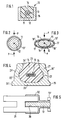
- the piezoelectric measuring element 11 is divided into a larger rigid waveguide 13 'retracted (Fig. 2). Both the waveguide 13 'and also the piezoelectric measuring element 11 originally have a round cross-section. Then the waveguide 13 'along a line perpendicular to its central longitudinal axis extending axis P so flattened that it assumes an approximately oval cross section and the in of this pressure axis P oriented outer wall sections 16 of the piezoelectric measuring element 11 between its wall sections under pressure and facing away from each other clamped.
- the remaining unaffected wall sections 16 'of the piezoelectric measuring element 11 are therefore opposite to the inner wall sections facing them of the waveguide 13 'spaced so that in the cross-sectional plane of the sensor 10 perpendicular to Pressure axis P on both sides of the piezoelectric measuring element 11 each form a cavity 17.
- the waveguide 13 ' is in the sealing compound 14 embedded as a means of transmission for incoming pressure waves.
- These pressure waves work with their vertical components on the between the Waveguide clamped wall sections 16 of the piezoelectric Measuring element while horizontal components be eliminated.
- the senor is in a profile tube 15 'with a C-shaped inner cross section arranged, the two protruding from a web 20 Legs 21, 21 'with undercuts 22, 22' the longitudinal edges 24, 24 'delimiting the open side 23 has and in the installed position with its open side the Surface of the road surface is facing.
- a secure position of the sensor in the sealing compound and thus reached in the profile tube This ensures that the recorded in the potting compound 14 Sensor 10 has a precisely defined measuring axis within the Has profile tube.
- connection adapter 31 is an embodiment of the invention Wheel load sensor shown, one over the waveguide 13 'protruding end of the inner electrode 12 in an end recess 30 one in longitudinal section H-shaped connection adapter 31 is added and a End portion 32 of the tubular piezoelectric Measuring element 11 the connection adapter 31st sealingly encloses.
Landscapes
- Physics & Mathematics (AREA)
- General Physics & Mathematics (AREA)
- Force Measurement Appropriate To Specific Purposes (AREA)
- Road Signs Or Road Markings (AREA)
- Measuring Fluid Pressure (AREA)
Description
- Fig. 1
- einen Radlastsensor nach dem Stand der Technik mit einem innerhalb eines Profilrohres aufgenommenen und in Vergußmasse eingebetteten piezoelektrischen Meßelement in einem Querschnitt,
- Fig. 2
- ebenfalls in einem Querschnitt ein in einem ersten Verfahrensschritt in einen Übermaß aufweisenden Hohlleiter eingezogenes piezoelektrisches Meßelement,
- Fig. 3
- in einer Ansicht wie in Fig. 2 die Anordnung aus piezoelektrischem Meßelement und Hohlleiter nach dem Flachdrücken des Hohlleiters in einem zweiten Verfahrensschritt, wobei das piezoelektrische Meßelement zwischen voneinander abgewandten deformierten Wandabschnitten des Hohlleiters eingespannt ist,
- Fig. 4
- in einer Ansicht wie in Fig. 1 einen nach dem erfindungsgemäßen Verfahren hergestellten Radlastsensor, bei dem das piezoelektrische Meßelement in einem Profilrohr mit C-förmigem Innenprofil aufgenommen und in Verbundmasse eingebettet ist und
- Fig. 5
- einen dicht mit dem Ende des piezoelektrischen Meßelementes verbundenen Anschlußadapter in einer Längsschnittansicht.
Claims (11)
- In einer Vergußmasse positionierter Radlastsensor für den Einbau in eine Aussparung eines Straßenbelags oder dergleichen, mit einem als Kabel ausgebildeten piezoelektrischen Meßelement, das einen als Innenelektrode dienenden Leiter umschließt und von wenigstens einem Hohlleiter als Außenelektrode umschlossen sowie in den Belag einer Fahrbahn einbaubar ist,
dadurch gekennzeichnet,
daß diejenigen Wandabschnitte (16) des piezoelektrischen Meßelementes (11), die in der Einbaulage zur Ebene des Straßenbelages etwa parallel verlaufen, unter vorbestimmter Druckspannung zwischen daran angrenzenden Wandbereichen des die Außenelektrode bildenden Hohlleiters (13') und die übrigen Wandabschnitte (16') des piezoelektrischen Meßelementes (11) im Hohlleiter beabstandet von dessen sonstigen Wandungen aufgenommen sind. - Radlastsensor nach Anspruch 1, dadurch gekennzeichnet, daß die Ausdehnung des Hohlleiters (13') in Einspannrichtung des piezoelektrischen Meßelements (11) kleiner als in einer dazu senkrechten Richtung ist.
- Radlastsensor nach Anspruch 1 oder 2, dadurch gekennzeichnet, daß der das piezoelektrische Meßelement (11) umschließende Hohlleiter (13) einen etwa ovalen Querschnitt aufweist.
- Radlastsensor nach einem der Ansprüche 1 bis 3, dadurch gekennzeichnet, daß die unter Druckspannung an dem Hohlleiter (13') anliegenden Wandabschnitte (16) des piezoelektrischen Meßelementes (11) annähernd planparallel sind.
- Radlastsensor nach einem der Ansprüche 1 bis 4, dadurch gekennzeichnet, daß das piezoelektrische Meßelement (11) in einem - in der Einbaulage - quer zur Fahrtrichtung verlaufenden Profilrohr (15) mit offener Oberseite (23) positioniert ist.
- Radlastsensor nach Anspruch 5, dadurch gekennzeichnet, daß das Profilrohr (15') zwei von einem Steg (20) vorstehende Schenkel (21, 21') sowie ein C-förmiges Innenprofil mit Hinterschneidungen (22, 22') der die Offenseite begrenzenden Profilkanten (24, 24') aufweist.
- Radlastsensor nach Anspruch 6, dadurch gekennzeichnet, daß der Steg (20) des Profilrohrs (15') als Standfuß mit beidseitig über seine Schenkel (21, 21') vorstehenden Randflanschen (25, 25') ausgebildet ist.
- Radlastsensor nach einem der Ansprüche 1 bis 7, gekennzeichnet durch eine Sicherung gegen das Eindringen von Feuchtigkeit zwischen die Innenelektrode (12) und das diese umgebende piezoelektrische Meßelement (11) mittels eines Anschlußadapters (31), wobei das Ende der Innenelektrode (12), das über den Hohlleiter (13') vorsteht, in einem Schlitz (30) des Adapters (31) aufgenommen sind und der den Schlitz (30) umgebende Bereich des Adapters dicht mit dem piezoelektrischen Meßelement (11) verbunden ist.
- Radlastelement nach Anspruch 8, dadurch gekennzeichnet, daß es sich bei dem Anschlußadapter (31) um einen H-förmigen Metalleiter handelt, in den sich von einer Stirnseite aus der ein Ende der Innenelektrode (12) aufnehmende Schlitz (30) hineinerstreckt und der schlitzseitig von einem Endabschnitt (32) eines das piezoelektrische Meßelement (11) bildenden Mantels dicht umschlossen ist.
- Verfahren zum Herstellen des Radlastsensors nach einem der Ansprüche 1 bis 9, dadurch gekennzeichnet, daß das piezoelektrische Meßelement (11) mit der in diesem aufgenommenen Innenelektrode (12) in einen Übermaß aufweisenden Hohlleiter (13') eingezogen und danach der Hohlleiter derart flachgedrückt wird, daß das piezoelektrische Meßelement mit voneinander abgewandten Wandabschnitten (16) zwischen den flachgedrückten Wandbereichen des Hohlleiters unter Druck eingespannt wird und zwischen den unbeaufschlagten Außenwandabschnitten (16') des piezoelektrischen Meßelementes und den diesen zugewandten Wandungen des Hohlleiters (13') Hohlräume (17) ausgebildet werden, und daß der das piezoelektrische Meßelement aufnehmende Hohlleiter (13') derart in Vergußmasse eingebettet wird, daß - in der Einbaulage - seine eingespannten Wandbereiche (16) sich im wesentlichen parallel zur Oberfläche des Straßenbelages erstrecken.
- Verfahren nach Anspruch 10, gekennzeichnet durch Verwendung eines im Querschnitt ursprünglich runden Hohlleiters (13'), der beim Flachdrücken in eine im Querschnitt ovale Form gebracht wird.
Applications Claiming Priority (2)
| Application Number | Priority Date | Filing Date | Title |
|---|---|---|---|
| DE4333532A DE4333532A1 (de) | 1993-10-01 | 1993-10-01 | Radlastsensor mit piezoelektrischem Meßelement sowie Verfahren zum Herstellen des Radlastsensors |
| DE4333532 | 1993-10-01 |
Publications (2)
| Publication Number | Publication Date |
|---|---|
| EP0646777A1 EP0646777A1 (de) | 1995-04-05 |
| EP0646777B1 true EP0646777B1 (de) | 1998-02-18 |
Family
ID=6499191
Family Applications (1)
| Application Number | Title | Priority Date | Filing Date |
|---|---|---|---|
| EP94113504A Expired - Lifetime EP0646777B1 (de) | 1993-10-01 | 1994-08-30 | Radlastsensor mit piezoelektrischem Messelement sowie Verfahren zum Herstellen des Radlastsensors |
Country Status (7)
| Country | Link |
|---|---|
| US (1) | US5571961A (de) |
| EP (1) | EP0646777B1 (de) |
| JP (1) | JP2562284B2 (de) |
| AT (1) | ATE163322T1 (de) |
| CA (1) | CA2132060C (de) |
| DE (2) | DE4333532A1 (de) |
| ES (1) | ES2112456T3 (de) |
Families Citing this family (7)
| Publication number | Priority date | Publication date | Assignee | Title |
|---|---|---|---|---|
| EP0866323A3 (de) * | 1997-02-25 | 1999-02-17 | K.K. Holding AG | Messplattform für Gewichts- und Bremssystem-Monitoring Anlagen |
| FR2785678B1 (fr) * | 1998-11-05 | 2001-01-26 | France Etat Ponts Chaussees | Procede et appareil pour mesurer la portance d'une plateforme |
| KR101498417B1 (ko) * | 2014-02-04 | 2015-03-04 | 김한구 | 압전센서 및 그 제작방법 |
| KR101472550B1 (ko) * | 2014-06-16 | 2014-12-16 | (주)노바코스 | 피에조센서 제조방법 |
| DE102016211102A1 (de) * | 2016-06-22 | 2017-12-28 | Robert Bosch Gmbh | Konzept zum Erfassen von Verkehrsinformationen |
| KR101998983B1 (ko) | 2017-12-11 | 2019-10-01 | 한국건설기술연구원 | 진동, 압력 측정을 위한 피에조 센서 및 그 피에조센서의 제조방법 |
| CN112585504B (zh) * | 2018-09-19 | 2025-05-02 | 三井化学株式会社 | 人体检测装置、床装置及人体检测系统 |
Family Cites Families (10)
| Publication number | Priority date | Publication date | Assignee | Title |
|---|---|---|---|---|
| FR2567550A1 (fr) * | 1984-07-13 | 1986-01-17 | Electronique Controle Mesure | Preparation et pose de capteurs piezo-electriques coaxiaux dans une chaussee |
| US4712423A (en) * | 1985-01-04 | 1987-12-15 | Laboratoire Central Des Ponts Et Chaussees | Process and apparatus for measuring the dynamic loads applied to a highway by the road traffic |
| DE3666505D1 (en) * | 1986-01-29 | 1989-11-23 | France Etat | Method for measuring dynamic charges exerted on a road by the traffic |
| FR2596568B1 (fr) * | 1986-03-25 | 1989-10-27 | Thomson Csf | Cable piezoelectrique et procede de fabrication d'un cable |
| US4958306A (en) * | 1988-01-06 | 1990-09-18 | Pacific Northwest Research & Development, Inc. | Pavement inspection apparatus |
| US4799381A (en) * | 1988-02-21 | 1989-01-24 | Cmi International, Inc. | Vehicle road sensor |
| US5448232A (en) * | 1989-05-03 | 1995-09-05 | Mitron Systems Corporation | Roadway sensors and method of installing same |
| US5463385A (en) * | 1989-05-03 | 1995-10-31 | Mitron Systems Corporation | Roadway sensor systems |
| JP2774322B2 (ja) * | 1989-08-04 | 1998-07-09 | アイシン精機株式会社 | 走行路面状態判定装置 |
| CH683714A5 (de) * | 1990-12-19 | 1994-04-29 | Kk Holding Ag | Kraftsensoranordnung, insbesondere zur dynamischen Achslast-, Geschwindigkeits-, Achsabstands- und Gesamtgewichtsbestimmung von Fahrzeugen. |
-
1993
- 1993-10-01 DE DE4333532A patent/DE4333532A1/de not_active Withdrawn
-
1994
- 1994-08-30 EP EP94113504A patent/EP0646777B1/de not_active Expired - Lifetime
- 1994-08-30 ES ES94113504T patent/ES2112456T3/es not_active Expired - Lifetime
- 1994-08-30 AT AT94113504T patent/ATE163322T1/de active
- 1994-08-30 DE DE59405271T patent/DE59405271D1/de not_active Expired - Lifetime
- 1994-09-14 JP JP6220528A patent/JP2562284B2/ja not_active Expired - Lifetime
- 1994-09-14 CA CA002132060A patent/CA2132060C/en not_active Expired - Lifetime
- 1994-09-30 US US08/316,579 patent/US5571961A/en not_active Expired - Lifetime
Also Published As
| Publication number | Publication date |
|---|---|
| CA2132060A1 (en) | 1995-04-02 |
| US5571961A (en) | 1996-11-05 |
| EP0646777A1 (de) | 1995-04-05 |
| DE4333532A1 (de) | 1995-04-06 |
| CA2132060C (en) | 2004-11-16 |
| ES2112456T3 (es) | 1998-04-01 |
| ATE163322T1 (de) | 1998-03-15 |
| JPH07174648A (ja) | 1995-07-14 |
| DE59405271D1 (de) | 1998-03-26 |
| JP2562284B2 (ja) | 1996-12-11 |
Similar Documents
| Publication | Publication Date | Title |
|---|---|---|
| EP0491655B1 (de) | Kraftsensorsystem, insbesondere zur dynamischen Achslast-, Geschwindigkeits-Achsabstands- und Gesamtgewichtsbestimmung von Fahrzeugen | |
| DE60200789T2 (de) | Verkehrsüberwachungssystem | |
| DE19751167C1 (de) | Profilstab | |
| DE3635053C2 (de) | Verfahren zum Überwachen der Verformungen von Bauteilen mittels Lichtwellenleitern sowie Lichtwellenleiter zur Durchführung des Verfahrens und Verfahren zu seiner Herstellung | |
| EP1215347B1 (de) | Verfahren zum Einbauen und Spannen eines freigespannten Zugglieds, sowie Verankerungsvorrichtung zum Durchführen des Verfahrens | |
| DE2943956A1 (de) | Verfahren zum installieren von magnetischen sensorschleifen in mehrspurigen strassen und zugehoerige testeinheit | |
| EP0646777B1 (de) | Radlastsensor mit piezoelektrischem Messelement sowie Verfahren zum Herstellen des Radlastsensors | |
| DE3218517C2 (de) | Tübbingausbau für Tunnels, Stollen o.dgl. und Meßgerät zur Überprüfung der Fugenbreite eines derartigen Tübbingausbaues | |
| DE68908144T2 (de) | Ausdehnungsmesssonde zur Messung der Belastung für ein Bohrelement. | |
| EP0342253A1 (de) | Kraftaufnehmer zum Einbau in Messplattformen | |
| DE69531656T2 (de) | Verfahren zur Messung von mechanischen Spannungen in Fahrzeugen | |
| EP3441726A1 (de) | Verfahren zur lösbaren befestigung von clamp-on-ultraschall-durchfluss-sensoren und anklemmvorrichtung hierzu sowie eine spanneinheit | |
| DE2263145C3 (de) | Meßaufnehmer für Rad- oder Achslasten von Straßenfahrzeugen | |
| DE19958163C1 (de) | Profilstabsystem | |
| DE10216760A1 (de) | Fahrzeugerfassungsvorrichtung | |
| DE102016107860B4 (de) | Messvorrichtung für eine Fuge in einem Bauwerk, Verwendung einer Messvorrichtung zur Messung einer Verformung einer Fuge in einem Bauerk und Verfahren zum Einbringen einer Messvorrichtung in ein Bauwerk | |
| DE9321447U1 (de) | Radlastsensor mit piezoelektrischem Meßelement | |
| DE19605036A1 (de) | Seilkraftaufnehmer | |
| CH679950A5 (en) | Railway line or beam force measurement appts. | |
| DE9116890U1 (de) | Kraftsensorsystem, insbesondere zur dynamischen Achslast-, Geschwindigkeits-, Achsabstands- und Gesamtgewichtsbestimmung von Fahrzeugen | |
| DE102024210287B3 (de) | Sensoreinrichtung zum erfassen von dehnungen an einem linienförmigen infrastrukturbauteil, insbesondere einer gleisschiene, messanordnung, verfahren und applikationsvorrichtung | |
| DE3424248A1 (de) | Bohrlochsonde | |
| DE10354281A1 (de) | Sensor | |
| DE69201542T2 (de) | Vorrichtung zur Einstellung der Position eines Kraftfahrzeugstossfängers. | |
| DE10318482B3 (de) | Vorrichtung zum Messen relativer Beschleunigungen |
Legal Events
| Date | Code | Title | Description |
|---|---|---|---|
| PUAI | Public reference made under article 153(3) epc to a published international application that has entered the european phase |
Free format text: ORIGINAL CODE: 0009012 |
|
| AK | Designated contracting states |
Kind code of ref document: A1 Designated state(s): AT DE ES FR GB IT |
|
| 17P | Request for examination filed |
Effective date: 19950617 |
|
| 17Q | First examination report despatched |
Effective date: 19961128 |
|
| GRAG | Despatch of communication of intention to grant |
Free format text: ORIGINAL CODE: EPIDOS AGRA |
|
| GRAG | Despatch of communication of intention to grant |
Free format text: ORIGINAL CODE: EPIDOS AGRA |
|
| GRAH | Despatch of communication of intention to grant a patent |
Free format text: ORIGINAL CODE: EPIDOS IGRA |
|
| GRAH | Despatch of communication of intention to grant a patent |
Free format text: ORIGINAL CODE: EPIDOS IGRA |
|
| RAP1 | Party data changed (applicant data changed or rights of an application transferred) |
Owner name: KIH KOMMUNIKATIONS INDUSTRIE HOLDING AKTIENGESELLS |
|
| GRAA | (expected) grant |
Free format text: ORIGINAL CODE: 0009210 |
|
| AK | Designated contracting states |
Kind code of ref document: B1 Designated state(s): AT DE ES FR GB IT |
|
| REF | Corresponds to: |
Ref document number: 163322 Country of ref document: AT Date of ref document: 19980315 Kind code of ref document: T |
|
| ITF | It: translation for a ep patent filed | ||
| GBT | Gb: translation of ep patent filed (gb section 77(6)(a)/1977) |
Effective date: 19980219 |
|
| REF | Corresponds to: |
Ref document number: 59405271 Country of ref document: DE Date of ref document: 19980326 |
|
| REG | Reference to a national code |
Ref country code: ES Ref legal event code: FG2A Ref document number: 2112456 Country of ref document: ES Kind code of ref document: T3 |
|
| ET | Fr: translation filed | ||
| PLBQ | Unpublished change to opponent data |
Free format text: ORIGINAL CODE: EPIDOS OPPO |
|
| PLBI | Opposition filed |
Free format text: ORIGINAL CODE: 0009260 |
|
| 26 | Opposition filed |
Opponent name: THE WHITAKER CORPORATION Effective date: 19981118 |
|
| PLBF | Reply of patent proprietor to notice(s) of opposition |
Free format text: ORIGINAL CODE: EPIDOS OBSO |
|
| PLBF | Reply of patent proprietor to notice(s) of opposition |
Free format text: ORIGINAL CODE: EPIDOS OBSO |
|
| PLBL | Opposition procedure terminated |
Free format text: ORIGINAL CODE: EPIDOS OPPC |
|
| REG | Reference to a national code |
Ref country code: FR Ref legal event code: TP |
|
| REG | Reference to a national code |
Ref country code: GB Ref legal event code: 732E |
|
| PLBM | Termination of opposition procedure: date of legal effect published |
Free format text: ORIGINAL CODE: 0009276 |
|
| STAA | Information on the status of an ep patent application or granted ep patent |
Free format text: STATUS: OPPOSITION PROCEDURE CLOSED |
|
| 27C | Opposition proceedings terminated |
Effective date: 19991204 |
|
| REG | Reference to a national code |
Ref country code: ES Ref legal event code: PC2A |
|
| REG | Reference to a national code |
Ref country code: GB Ref legal event code: IF02 |
|
| PGFP | Annual fee paid to national office [announced via postgrant information from national office to epo] |
Ref country code: ES Payment date: 20130813 Year of fee payment: 20 Ref country code: DE Payment date: 20130829 Year of fee payment: 20 Ref country code: AT Payment date: 20130726 Year of fee payment: 20 |
|
| PGFP | Annual fee paid to national office [announced via postgrant information from national office to epo] |
Ref country code: GB Payment date: 20130828 Year of fee payment: 20 Ref country code: FR Payment date: 20130808 Year of fee payment: 20 |
|
| PGFP | Annual fee paid to national office [announced via postgrant information from national office to epo] |
Ref country code: IT Payment date: 20130806 Year of fee payment: 20 |
|
| REG | Reference to a national code |
Ref country code: DE Ref legal event code: R071 Ref document number: 59405271 Country of ref document: DE |
|
| REG | Reference to a national code |
Ref country code: GB Ref legal event code: PE20 Expiry date: 20140829 |
|
| REG | Reference to a national code |
Ref country code: AT Ref legal event code: MK07 Ref document number: 163322 Country of ref document: AT Kind code of ref document: T Effective date: 20140830 |
|
| PG25 | Lapsed in a contracting state [announced via postgrant information from national office to epo] |
Ref country code: DE Free format text: LAPSE BECAUSE OF EXPIRATION OF PROTECTION Effective date: 20140902 |
|
| PG25 | Lapsed in a contracting state [announced via postgrant information from national office to epo] |
Ref country code: GB Free format text: LAPSE BECAUSE OF EXPIRATION OF PROTECTION Effective date: 20140829 |
|
| REG | Reference to a national code |
Ref country code: ES Ref legal event code: FD2A Effective date: 20150107 |
|
| PG25 | Lapsed in a contracting state [announced via postgrant information from national office to epo] |
Ref country code: ES Free format text: LAPSE BECAUSE OF EXPIRATION OF PROTECTION Effective date: 20140831 |