EP0646801B1 - Appareil de test pour tester et manipuler un nombre de dispositifs - Google Patents
Appareil de test pour tester et manipuler un nombre de dispositifs Download PDFInfo
- Publication number
- EP0646801B1 EP0646801B1 EP93115094A EP93115094A EP0646801B1 EP 0646801 B1 EP0646801 B1 EP 0646801B1 EP 93115094 A EP93115094 A EP 93115094A EP 93115094 A EP93115094 A EP 93115094A EP 0646801 B1 EP0646801 B1 EP 0646801B1
- Authority
- EP
- European Patent Office
- Prior art keywords
- test
- level
- testing apparatus
- tasks
- operating
- Prior art date
- Legal status (The legal status is an assumption and is not a legal conclusion. Google has not performed a legal analysis and makes no representation as to the accuracy of the status listed.)
- Expired - Lifetime
Links
Images

Classifications
-
- G—PHYSICS
- G01—MEASURING; TESTING
- G01R—MEASURING ELECTRIC VARIABLES; MEASURING MAGNETIC VARIABLES
- G01R31/00—Arrangements for testing electric properties; Arrangements for locating electric faults; Arrangements for electrical testing characterised by what is being tested not provided for elsewhere
- G01R31/28—Testing of electronic circuits, e.g. by signal tracer
- G01R31/2832—Specific tests of electronic circuits not provided for elsewhere
- G01R31/2834—Automated test systems [ATE]; using microprocessors or computers
Definitions
- This invention relates to a testing apparatus and a method for testing and handling a multiplicity of devices. More specifically, it relates to a tester for testing electronic circuitry, particularly integrated circuits.
- Electronic testing equipment such as integrated circuit or board testers. has become more and more complex over the last decades. This is particularly due to the increased functionality of the circuitry to be tested - e.g., latest microprocessors, RISC CPU's. combined logic/memory IC's -, which calls for complex test procedures and high-sophisticated tester equipment.
- the integrated test environment does not only include the tester itself. but also supporting machinery, e.g., a prober or handler for automatic supply and exchange of devices to be tested (DUT's, e.g., integrated circuits or loaded or unloaded boards).
- DUT's devices to be tested
- the handling machinery has to be able to deal with several physical or logical entities, such as lots or cassettes containing DUT's, and process them in the correct order.
- logical or physical entities which have to be handled by the tester itself (not by additional handling tools); a common example is a wafer containing a multiplicity of integrated circuits (IC's) of the same kind.
- the contacts of the test head have to be advanced from one die to the next one as soon as the first one has been tested (or the wafer has to be advanced instead), and the correct steps have to be taken when the complete wafer has been tested (e.g., the wafer has to be removed and replaced with the next one).
- control equipment by the customer is a laborious and time-consuming task.
- the manufacturers of IC or board testers have therefore already tried to meet the customer's demands by the provision of configurable control programs, i.e. control programs which permit adaptation to a specific test environment.
- control programs i.e. control programs which permit adaptation to a specific test environment.
- control equipment so far known in the art is still difficult and complex to operate. This is mainly due to the fact that the complete sequence of control functions has to be defined without any supporting structure, and that the operator is forced never to loose sight of the overall process, despite of the specific part of the process he is editing. His task can thus still be described as fully-qualified programming, despite of the available tools, with all related requirements in terms of time and work.
- EP-A-0 296 884 discloses a system for in-circuit testing of an electronic circuit device which utilizes a distributed processing architecture wherein separate controllers are used to control the testing and for data collection and correlation of the collected data to the testing conditions.
- the testing may be conducted by sending test vector addresses from the test controller to each of the driver/sensor boards in the tester electronics, which addresses, in turn, are used to access driver memories containing the test conditions corresponding to the test vector addresses.
- the circuit containing the device is powered up and a tester coupling mechanism is connected to the terminals of the device. Determinations are made of the physical orientation of the device with respect to the tester coupling mechanism, and of whether the device terminals are in electrical contact with the tester mechanism and with the other components of the circuit.
- EP-A-0 296 884 represents the closest prior art and, in particular, discloses a testing apparatus for testing and handling a multiplicity of devices comprising a test executor provided for controlling operation of the individual test steps, at least one test adapter for receiving at least one device to be tested, a multiplicity of physical or logical entities in which the devices to be tested are arrange, a return from a specific level to another one, and the use of a device test processor.
- EP-A-0 068 994 discloses a method of testing with computers, wherein a unit is tested by a test instrument with the aid of a master, an intermediate and a slave computer. The latter connects to the test instrument for sensing its measurements.
- the method includes the step of despatching one of a plurality of instruction signals to the intermediate computer from the master computer. Another step is issuing to the slave computer, when it is not halted, a signal to halt from the intermediate computer after receipt by the intermediate computer of one of the instruction signals. Another step is transmitting from the intermediate to the slave computer, after the latter has halted, that one of a plurality of command signals corresponding to the currently dispatched one of the instruction signals.
- the method also includes the step of forwarding a go signal to the intermediate computer from the master computer and issuing to the slave computer from the intermediate computer a run signal signifying a request to run and sense measurements from the test instrument.
- the present invention relates to a tester which includes a new test executor (or test program executor, i.e., the device which controls overall operation of the test).
- This test executor permits a "structured" set-up.
- a testing apparatus according to the invention comprises the features of claim 1.
- the invention also relates to embodiments with test level controllers incorporating a pre-activity sequence of tasks only, or a post-activity sequence of tasks only.
- the testing apparatus includes a test executor for performing and controlling the necessary steps of testing and test processing. For this purpose, it controls a test adapter which receives the DUT (in case of an IC tester, this may be a test socket), as well as handling tools for processing the physical or logical entities into which the DUT's are arranged. Again referring to an IC tester, such a handling tool may be a prober or handler.
- the test executor comprises a high-sophisticated structural segmentation. Specifically, it makes use of a "level model" which reflects all of the various handling or packaging entities, in descending order. Every logical or physical entity into which the devices to be tested are arranged is reflected by a corresponding (physical or logical) hierarchical operating level. It is important to note that the entities in which the DUT's are arranged are not entities of equal importance, such as ceramic packaging versus plastic packaging. Instead, the operating levels are arranged such that an entity at a certain level comprises, i.e., includes at least one, but preferably multiple entities of lower order (this is why the term "hierarchical operating level" has been used).
- each cassette contains multiple wafers.
- the hierarchical operating levels "cassette - wafer - IC”. If the cassettes are arranged in lots (which is, by the way, a logical entity, in contrast to the physical entities so far discussed), we have the levels "lot - cassette - wafer - IC". It is worth mentioning that this is a preferred embodiment of the invention. However, if we look, e.g., at a tester for parts of the automobile industry, the levels could be "lot - box - package - part".
- each test level controller includes preferably:
- test level controller structure is of a very general, uniform and easy-to-learn nature. As soon as a test level controller has completed its pre-activity task sequence, it calls a test level controller at a lower level. If appropriate, this further test level controller calls deeper levels, and then returns operation to the calling test level controller. That is, the test operation is segmented into a "cascaded structure".
- test level controllers are of basically the same kind, and thus easy to learn and to apply. They implement a uniform structure which does not require an extensive learning curve. Thus, a lot of time and money can be saved.
- the engineer at a production floor may easily adapt the operating environment to his needs. He does not have to train his operators (of lower skills) to the complete given test environment.
- the easy process of customization e.g., interactive changes
- the present invention allows to keep to the knowledge and traditions already present at the relevant production floor. This increases safety and reliability, as the tester so-to-say adapts to human knowledge, instead of createing a need to adapt a human being to machine demands.
- the device test modules can be easily replaced, or additional device test modules can be included, without interfering with the existing structure.
- this is the most common case, as the features of IC's or other devices to be tested are constantly enhanced, whereas the overall test equipment is seldom modified.
- test level controller may be repeated without return to the preceding level (e.g., in dependence of the test results), or the call of the next lower level may be skipped. It is also possible to call another test level controller at the same operating level. All of this functionality may be performed under operator or automatic control.
- the present invention is particularly suited for integrated circuit testers or board testers. However, it may also be useful for other kinds of testing equipment, such as test of goods upon delivery, mechanical testing, quality tests and the like.
- the invention also relates to a method for testing and handling a multiplicity of devices according to claim 13.
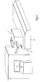
- IC tester integrated circuit tester
- a display 2 a keyboard 3 and all of the control circuitry required to test an integrated circuit, in particular a test controller or executor (which is basically a computer system).
- a test controller or executor which is basically a computer system.
- the outer appearance mav also be quite different; e.g., the data console may be separated from the tester itself.
- Leads 4 connect the IC tester with a test head 5 for applying and contacting integrated circuits, or wafers to be tested (the so-called "DUT's", i.e., devices under test).
- Device 6 is a handler able to handle cassettes which, in turn, contain wafers to be tested (the mechanical details of handler 6 are not shown in detail in Fig. 1, as they are anyway well known in the art).
- the handler takes a wafer from a cassette and applies it to test head 5 which sits right on top of the handler.
- the apparatus proceeds from IC to IC on a single wafer by advancing the wafer under test head 5 (of course, one could also move the test head instead, but this is not common practice). Tested wafers are removed and replaced by untested wafers. The same applies to cassettes.
- the cassettes pertain to one lot of DUT's to be tested, we can thus divide the test process into various logical and physical entities in a hierarchical order.
- the entity of the highest order is the lot, i.e., the totality of the cassettes (this is a logical entity, as no common packaging, or other tangible means which keep the cassettes physically together, is provided for all of the cassettes). If we go on in descending order, the next operating levels are the cassette level, the wafer level and the IC (die) level. All of these entities are physical entities, as their elements are kept together by physical means.
- automated test processing requires that all steps are performed in the correct order. For example, once all wafers in a cassette have been tested, the apparatus has automatically to advance to the first wafer in the next cassette. Likewise, after the (successful or unsuccessful) test of a die, the apparatus has to advance to the next die, but only until all dice on the wafer have been tested, in which case the wafer has to be exchanged.
- test environment shown in Fig. 1 is only an exemplary embodiment. It will be noted that there exist a variety of alternate embodiments; for example, the "lot" level may be removed, the wafers may be packed in other units than cassettes (e.g., racks), or they may not be packed at all. Likewise, the hierarchical structure is different in case the devices under test are not wafers, but rather IC's (either unpacked or packed, such as in dual-in-line-packages). Yet another example are the various test adapters available on the market.
- the user of the test environment i.e., the "customer” from the viewpoint of the manufacturer of the tester
- the test controller has to be able to adapt the test controller to his specific embodiment and demands, and it will be appreciated that this may be a costly, time-consuming and error-prone process.
- Fig. 2 depicts a structural diagram of such a test level controller 10.
- Operation starts at arrow 11. This is the entry from the next higher operating level (provided one exists; if not, it is simply the call from a supervisor program or an operating system).
- Box 12 includes a set of so-called "pre-activity sequence of tasks”. i.e., tasks or actions to be performed at this very level before the next lower level is called, such as a dialog with the operator (more examples will be discussed below). Operation then proceeds to the next lower hierarchical operating level, as indicated by arrow 13.
- test level controller 10 When the test level controller at the next lower level has performed its task (which may include calls to even lower levels), operation returns to test level controller 10, see arrow 14. The test level controller then executes a set of "post-activity sequence of tasks" 15, like data logging (see more detailed discussion below). Thereafter, operation returns to the calling process, i.e., the next higher operating level (arrow 16).
- test level controllers at each operating level are of basically similar structural design, we obtain thus a unified, "stacked" overall structure which permits easy modification and adaptation.
- a “sample” test executor may be provided to the customer for the purpose of adaptation, such that he does not have to start from scratch when creating his own test procedure.
- the test level - contains the "device test processors", i.e., processors which directly execute the test of a die, such as test of the leakage current, the DC characteristics, the AC transmission characteristics, the response time etc. of a specific IC.
- device test processors i.e., processors which directly execute the test of a die, such as test of the leakage current, the DC characteristics, the AC transmission characteristics, the response time etc. of a specific IC.
- the operator renders (during the pre-activity sequence of tasks) an instruction to skip an operating level, or that this information is retrieved from an execution input file.
- the call of the next lower operating level may be skipped, as indicated by dashed arrow 17.
- a test level may be repeated (dashed arrow 18), e.g., if a specific test has failed.
- the last exception is continuation at the same test level, e.g..
- In response to an appropriate operator or command file instruction in the course of the pest-activity sequence of tasks (dashed arrow 19).
- Fig. 3 depicts the typical operation of the various test level controllers, as well as the device test processors, in the embodiment of Fig. 1 (time is running to the right).
- the "lot” level is designated as 20; likewise, the "cassette” level, the “wafer” level and the “die” level are labelled as 21, 22 and 23, respectively.
- the "test” level is below (23a). Boxes with hatching inclined to the right indicate a pre-activity sequence of tasks in Fig. 3, whereas hatching with inclination to the left indicates a post-activity sequence of tasks, and horizontal hatching relates to a device test processor.
- Operation starts at the "lot" level. namely the pre-activity task sequence 24 of the test level controller assigned to the lot level.
- the test level controllers execute now their respective pre-activity task sequences, as indicated by reference numbers 25. 26 and 27, and perform a call to the test level controller of the next lower level.
- a device test processor 28 performs an actual test of a die.
- the post-activity task sequences 29 and 30 of the corresponding test level controllers are restarted, as indicated by pre-activity task sequence boxes 31 and 32.
- the next die is tested by a device test processor (box 33).
- This scheme continues until three dice have been tested (assuming that one wafer carries three dice - this is not a very reasonable assumption which has only been made for purposes of illustration, as an actual wafer will carry considerably more dice), and all test level controllers execute their respective post-activity task sequences, see boxes 34, 35. 36 and 37. Again, processing of more than one wafer, or more than one cassette have not been shown in Fig. 3 for graphical purposes, but it will be understood that such processing is performed in basically the same manner as multiple dice are tested, although at higher levels of operation.
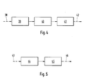
- Fig. 4 depicts a typical example of a pre-activity sequence of tasks to be performed by a test level controller. Entry into the pre-activity task sequence is indicated by dashed arrow 38.
- a first box 39 includes input of process data, such as level identification, sublevel count or reading data from an execution input file.
- Box 40 comprises a dialog with the operator, i.e., control command input such as an instruction to skip or repeat a level, to continue at the same level or to quit operation (cf. Fig. 2). (It will be understood that, instead of interactive operation, the respective instructions may also be read from a command file).
- box 41 includes instructions for handling devices, such as for handler 6 (Fig. 1), just before operation proceeds (dashed arrow 42).
- FIG. 5 A similar example of a post-activity task sequence is given in Fig. 5. After entry (dashed arrow 43), appropriate control commands are rendered to the handling device (box 44). Thereafter, data (such as test data obtained from a DUT) are logged, e.g., in a data log file (box 45), and operation proceeds (dashed arrow 46).
- data such as test data obtained from a DUT
- the post-activity task sequence may also include a dialog with the operator.
Landscapes
- Engineering & Computer Science (AREA)
- General Engineering & Computer Science (AREA)
- Computer Hardware Design (AREA)
- Microelectronics & Electronic Packaging (AREA)
- Physics & Mathematics (AREA)
- General Physics & Mathematics (AREA)
- Tests Of Electronic Circuits (AREA)
- Testing Of Individual Semiconductor Devices (AREA)
- Testing Electric Properties And Detecting Electric Faults (AREA)
- Testing Or Measuring Of Semiconductors Or The Like (AREA)
Claims (13)
- Appareil de test pour tester et manipuler une multiplicité de dispositifs, comprenant(1.1) un dispositif d'exécution de tests prévu pour commander l'exécution des étapes de test individuelles,(1.2) au moins un adaptateur de test (5) pour recevoir au moins un dispositif à tester,(1.3) une multiplicité d'entités physiques ou logiques, dans lesquelles les dispositifs à tester sont disposés, ledit dispositif d'exécution de test comprend au moins deux niveaux de fonctionnement hiérarchiques affectés chacun à l'une desdites entités physique ou logique et comprenant en outre(1.4) au moins un contrôleur de niveau de test (10) réglé de manière à exécuter au moins la séquence suivante d'étapes opératoires :et dans lequel(1.4.1) une séquence de tâches (12) de pré-activité, le cas échéant ;(1.4.2) un appel (13) envoyé à un niveau inférieur de fonctionnement hiérarchique ;(1.4.3) un retour (14) à partir dudit niveau inférieur de fonctionnement et ;(1.4.4) une séquence de tâches (15) de post-activité, le cas échéant ;(1.5) le niveau hiérarchique le plus faible de fonctionnement est traité par au moins un processeur (28, 33) de test de dispositifs prévu pour le test de paramètres de dispositifs individuels.
- Appareil de test selon la revendication 1, dans lequel le au moins un contrôleur de niveau de test (10) est réglé de manière à exécuter l'étape opératoire d'appel d'un niveau hiérarchique inférieur au moyen d'un appel du niveau hiérarchique immédiatement inférieur.
- Appareil de test selon la revendication 1 comportant au moins trois niveaux hiérarchiques de fonctionnement, dans lequel le contrôleur de niveau de test (10) affecté au niveau hiérarchique le plus élevé de fonctionnement est réglé pour envoyer un appel au contrôleur de niveau de test (10) affecté au niveau hiérarchique immédiatement inférieur de fonctionnement, et ainsi de suite jusqu'à ce que l'opération atteigne le niveau hiérarchique le plus bas de fonctionnement, auquel ledit processeur (28, 33) de test de dispositifs est affecté.
- Appareil de test selon la revendication 1, dans lequel le contrôleur de niveau de test (10) comprend, dans sa séquence de tâches de pré-activité, une instruction (17) pour sauter l'appel envoyé à un niveau hiérarchique inférieur de fonctionnement, si un indicateur approprié est réglé.
- Appareil de test selon la revendication 1, dans lequel le contrôleur de niveau de test (10) inclut, dans sa séquence de tâches de post-activité, une instruction (18) pour revenir à sa séquence de tâches de pré-activité si un indicateur approprié est réglé.
- Appareil de test selon la revendication 1, dans lequel le contrôleur de niveau de test (10) comprend, dans sa séquence de tâches de post-activité, une instruction (19) pour poursuivre le fonctionnement au même niveau hiérarchique de fonctionnement.
- Appareil de test selon la revendication 1 comprenant au moins un outil de manipulation (6) pour traiter lesdites entités physiques ou logiques.
- Appareil de test selon la revendication 1, dans lequel la séquence de tâches (12) de pré-activité inclut au moins l'une des tâches suivantes :introduction de données de processus (39),entrée de commandes (40),actionnement (41) d'au moins un outil de manipulation (6).
- Appareil de test selon la revendication 1, dans lequel la séquence de tâches (15) de post-activité comprend au moins l'une des actions suivantes :enregistrement de données (45),actionnement (44) d'au moins un outil de manipulation (6).
- Utilisation de l'appareil de test selon la revendication 1 en tant qu'appareil de test pour des composants électroniques.
- Utilisation de l'appareil de test selon la revendication 10 en tant qu'appareil de test pour circuits intégrés.
- Utilisation de l'appareil de test selon la revendication 10 lorsque les niveaux de fonctionnement hiérarchiques incluent au moins l'un des niveaux suivants :niveau de lot (20),niveau de cassette (21),niveau de pastille (22),niveau de dé (23).
- Procédé pour tester et manipuler une multiplicité de dispositifs, qui sont arrangés selon une multiplicité d'entités physiques et logiques, ledit procédé comprenant les étapes consistant à :selon lequel ledit contrôleur de niveau suivant est un processeur (28, 33) de test de dispositifs situé au niveau hiérarchique de fonctionnement le plus bas, et un autre contrôleur de niveau de test (10) dans tous les autres cas.(13.1) appeler un contrôleur de niveau de test (10),(13.2) exécuter une séquence de tâches (12) de pré-activité, le cas échéant ;(13.3) appeler (13) un contrôleur de niveau suivant à un niveau hiérarchique inférieur de fonctionnement ;(13.4) effectuer un retour (14) à partir dudit niveau hiérarchique inférieur de fonctionnement ;(13.5) exécuter une séquence de tâches (15) de post-activité, le cas échéant ;
Priority Applications (4)
| Application Number | Priority Date | Filing Date | Title |
|---|---|---|---|
| DE69326003T DE69326003T2 (de) | 1993-09-20 | 1993-09-20 | Testapparat zum Testen und Handhaben einer Vielzahl von Vorrichtungen |
| EP93115094A EP0646801B1 (fr) | 1993-09-20 | 1993-09-20 | Appareil de test pour tester et manipuler un nombre de dispositifs |
| US08/298,439 US5530370A (en) | 1993-09-20 | 1994-08-30 | Testing apparatus for testing and handling a multiplicity of devices |
| JP25119294A JP3444668B2 (ja) | 1993-09-20 | 1994-09-20 | テスト装置およびテスト方法 |
Applications Claiming Priority (1)
| Application Number | Priority Date | Filing Date | Title |
|---|---|---|---|
| EP93115094A EP0646801B1 (fr) | 1993-09-20 | 1993-09-20 | Appareil de test pour tester et manipuler un nombre de dispositifs |
Publications (2)
| Publication Number | Publication Date |
|---|---|
| EP0646801A1 EP0646801A1 (fr) | 1995-04-05 |
| EP0646801B1 true EP0646801B1 (fr) | 1999-08-11 |
Family
ID=8213279
Family Applications (1)
| Application Number | Title | Priority Date | Filing Date |
|---|---|---|---|
| EP93115094A Expired - Lifetime EP0646801B1 (fr) | 1993-09-20 | 1993-09-20 | Appareil de test pour tester et manipuler un nombre de dispositifs |
Country Status (4)
| Country | Link |
|---|---|
| US (1) | US5530370A (fr) |
| EP (1) | EP0646801B1 (fr) |
| JP (1) | JP3444668B2 (fr) |
| DE (1) | DE69326003T2 (fr) |
Families Citing this family (25)
| Publication number | Priority date | Publication date | Assignee | Title |
|---|---|---|---|---|
| US5774368A (en) * | 1995-10-20 | 1998-06-30 | Motorola, Inc. | Controller structure template and method for designing a controller structure |
| JPH10142293A (ja) * | 1996-11-12 | 1998-05-29 | Advantest Corp | Ic試験装置 |
| US6373260B1 (en) * | 1998-02-24 | 2002-04-16 | Agilent Technologies, Inc. | Single cable, single point, stimulus and response probing system and method |
| US6493841B1 (en) | 1999-03-31 | 2002-12-10 | Synopsys, Inc. | Method and apparatus for determining expected values during circuit design verification |
| US6499127B1 (en) | 1999-04-22 | 2002-12-24 | Synopsys, Inc. | Method and apparatus for random stimulus generation |
| US6449745B1 (en) | 1999-04-22 | 2002-09-10 | Synopsys, Inc. | Method and apparatus for random stimulus generation |
| US6553531B1 (en) | 1999-04-22 | 2003-04-22 | Synopsys, Inc. | Method and apparatus for random stimulus generation |
| US6513144B1 (en) | 1999-04-22 | 2003-01-28 | Synopsys, Inc. | Method and apparatus for random stimulus generation |
| US6427223B1 (en) * | 1999-04-30 | 2002-07-30 | Synopsys, Inc. | Method and apparatus for adaptive verification of circuit designs |
| KR20030083488A (ko) * | 2002-04-23 | 2003-10-30 | 삼성전자주식회사 | 집적 회로의 동작 테스트 방법 |
| DE10227332A1 (de) * | 2002-06-19 | 2004-01-15 | Akt Electron Beam Technology Gmbh | Ansteuervorrichtung mit verbesserten Testeneigenschaften |
| DE10253717B4 (de) * | 2002-11-18 | 2011-05-19 | Applied Materials Gmbh | Vorrichtung zum Kontaktieren für den Test mindestens eines Testobjekts, Testsystem und Verfahren zum Testen von Testobjekten |
| US6833717B1 (en) * | 2004-02-12 | 2004-12-21 | Applied Materials, Inc. | Electron beam test system with integrated substrate transfer module |
| US7355418B2 (en) * | 2004-02-12 | 2008-04-08 | Applied Materials, Inc. | Configurable prober for TFT LCD array test |
| US20060038554A1 (en) * | 2004-02-12 | 2006-02-23 | Applied Materials, Inc. | Electron beam test system stage |
| US7319335B2 (en) * | 2004-02-12 | 2008-01-15 | Applied Materials, Inc. | Configurable prober for TFT LCD array testing |
| US7535238B2 (en) * | 2005-04-29 | 2009-05-19 | Applied Materials, Inc. | In-line electron beam test system |
| US20070192346A1 (en) * | 2006-01-31 | 2007-08-16 | Carli Connally | Apparatus for storing variable values to provide context for test results that are to be formatted |
| US7519887B2 (en) * | 2006-01-31 | 2009-04-14 | Verigy (Singapore) Pte. Ltd. | Apparatus for storing and formatting data |
| CN101400991B (zh) * | 2006-03-14 | 2013-03-20 | 应用材料公司 | 减小多个柱状电子束测试系统中的串扰的方法 |
| US7786742B2 (en) * | 2006-05-31 | 2010-08-31 | Applied Materials, Inc. | Prober for electronic device testing on large area substrates |
| US7602199B2 (en) * | 2006-05-31 | 2009-10-13 | Applied Materials, Inc. | Mini-prober for TFT-LCD testing |
| US20090248234A1 (en) * | 2008-03-25 | 2009-10-01 | Honeywell International, Inc. | Methods and systems for controlling testing in vehicles |
| CN103189087B (zh) | 2010-10-29 | 2016-03-16 | 皇家飞利浦电子股份有限公司 | 雾化器、控制雾化器的控制单元以及雾化器的控制方法 |
| CN110514923B (zh) * | 2019-07-24 | 2022-02-08 | 北京吉盛机电设备有限公司 | 风阀执行器多功能检测试验台 |
Family Cites Families (8)
| Publication number | Priority date | Publication date | Assignee | Title |
|---|---|---|---|---|
| US4218745A (en) * | 1978-09-11 | 1980-08-19 | Lockheed Corporation | Microcomputer assisted electrical harness fabrication and testing system |
| US4417336A (en) * | 1981-06-18 | 1983-11-22 | The Bendix Corporation | Method of testing with computers |
| US4593820A (en) * | 1984-03-28 | 1986-06-10 | International Business Machines Corporation | Robotic, in-transit, device tester/sorter |
| EP0296884A3 (fr) * | 1987-06-24 | 1991-01-16 | Schlumberger Technologies, Inc. | Procédé pour tester in-circuit un dispositif électronique |
| US5023791A (en) * | 1990-02-12 | 1991-06-11 | The Boeing Company | Automated test apparatus for aircraft flight controls |
| DE69100204T2 (de) * | 1991-11-11 | 1994-01-13 | Hewlett Packard Gmbh | Einrichtung zur Erzeugung von Testsignalen. |
| EP0541837B1 (fr) * | 1991-11-11 | 1995-01-11 | Hewlett-Packard GmbH | Circuit de détection |
| DE69100176T2 (de) * | 1991-11-11 | 1993-10-28 | Hewlett Packard Gmbh | Impulsformerschaltung. |
-
1993
- 1993-09-20 DE DE69326003T patent/DE69326003T2/de not_active Expired - Fee Related
- 1993-09-20 EP EP93115094A patent/EP0646801B1/fr not_active Expired - Lifetime
-
1994
- 1994-08-30 US US08/298,439 patent/US5530370A/en not_active Expired - Lifetime
- 1994-09-20 JP JP25119294A patent/JP3444668B2/ja not_active Expired - Fee Related
Also Published As
| Publication number | Publication date |
|---|---|
| JP3444668B2 (ja) | 2003-09-08 |
| EP0646801A1 (fr) | 1995-04-05 |
| JPH07110365A (ja) | 1995-04-25 |
| DE69326003T2 (de) | 1999-11-25 |
| US5530370A (en) | 1996-06-25 |
| DE69326003D1 (de) | 1999-09-16 |
Similar Documents
| Publication | Publication Date | Title |
|---|---|---|
| US5530370A (en) | Testing apparatus for testing and handling a multiplicity of devices | |
| US7042243B2 (en) | Device test apparatus and test method including control unit(s) between controller and test units | |
| KR100270652B1 (ko) | 반도체디바이스반송처리장치 | |
| US5355320A (en) | System for controlling an integrated product process for semiconductor wafers and packages | |
| US9753081B2 (en) | Muxing interface platform for multiplexed handlers to reduce index time system and method | |
| US4771428A (en) | Circuit testing system | |
| JPWO1997009629A1 (ja) | 半導体デバイス搬送処理装置 | |
| GB2392251A (en) | Automatic integrated circuit testing system and device using an integrative computer and method for the same | |
| JPS62219150A (ja) | コンピユ−タ周辺装置の自動試験装置 | |
| US6505138B1 (en) | Function-based control interface for integrated circuit tester prober and handler devices | |
| US5161116A (en) | System for evaluating the performance of a large scale programmable machine capable of having a plurality of terminals attached thereto | |
| JP2005513444A (ja) | マイクロプロセッサに基づく集積回路検査のための測定 | |
| JPH0451788B2 (fr) | ||
| US20030060996A1 (en) | Semi-automated multi-site system tester | |
| US6038520A (en) | Method and apparatus for application's specific testing of assembled circuits | |
| US5968193A (en) | Dual site loadboard tester | |
| CN114065956A (zh) | 用于自动化生产线的点检方法、系统、设备及存储介质 | |
| JPH09318703A (ja) | Icハンドラ | |
| US5903146A (en) | Distributing test system and method | |
| JPH0850162A (ja) | 半導体装置の試験方法及び試験装置 | |
| JPS6014376B2 (ja) | 試験装置 | |
| JP3151877B2 (ja) | 部品実装方法及び装置 | |
| JP2002016118A (ja) | 半導体パラメトリック試験装置 | |
| CN118193038A (zh) | 一种自动化工装检测系统及方法、待检测工装 | |
| KR20030076098A (ko) | 테스트 핸들러 및 그 제어방법 |
Legal Events
| Date | Code | Title | Description |
|---|---|---|---|
| PUAI | Public reference made under article 153(3) epc to a published international application that has entered the european phase |
Free format text: ORIGINAL CODE: 0009012 |
|
| 17P | Request for examination filed |
Effective date: 19940812 |
|
| AK | Designated contracting states |
Kind code of ref document: A1 Designated state(s): DE GB |
|
| 17Q | First examination report despatched |
Effective date: 19970516 |
|
| GRAG | Despatch of communication of intention to grant |
Free format text: ORIGINAL CODE: EPIDOS AGRA |
|
| GRAG | Despatch of communication of intention to grant |
Free format text: ORIGINAL CODE: EPIDOS AGRA |
|
| GRAH | Despatch of communication of intention to grant a patent |
Free format text: ORIGINAL CODE: EPIDOS IGRA |
|
| GRAH | Despatch of communication of intention to grant a patent |
Free format text: ORIGINAL CODE: EPIDOS IGRA |
|
| GRAA | (expected) grant |
Free format text: ORIGINAL CODE: 0009210 |
|
| AK | Designated contracting states |
Kind code of ref document: B1 Designated state(s): DE GB |
|
| REF | Corresponds to: |
Ref document number: 69326003 Country of ref document: DE Date of ref document: 19990916 |
|
| PLBE | No opposition filed within time limit |
Free format text: ORIGINAL CODE: 0009261 |
|
| STAA | Information on the status of an ep patent application or granted ep patent |
Free format text: STATUS: NO OPPOSITION FILED WITHIN TIME LIMIT |
|
| 26N | No opposition filed | ||
| REG | Reference to a national code |
Ref country code: GB Ref legal event code: 732E |
|
| REG | Reference to a national code |
Ref country code: GB Ref legal event code: IF02 |
|
| PGFP | Annual fee paid to national office [announced via postgrant information from national office to epo] |
Ref country code: DE Payment date: 20060914 Year of fee payment: 14 |
|
| PGFP | Annual fee paid to national office [announced via postgrant information from national office to epo] |
Ref country code: GB Payment date: 20060920 Year of fee payment: 14 |
|
| GBPC | Gb: european patent ceased through non-payment of renewal fee |
Effective date: 20070920 |
|
| PG25 | Lapsed in a contracting state [announced via postgrant information from national office to epo] |
Ref country code: DE Free format text: LAPSE BECAUSE OF NON-PAYMENT OF DUE FEES Effective date: 20080401 |
|
| PG25 | Lapsed in a contracting state [announced via postgrant information from national office to epo] |
Ref country code: GB Free format text: LAPSE BECAUSE OF NON-PAYMENT OF DUE FEES Effective date: 20070920 |