EP0646810A2 - Messung der dielektrischen Eigenschaften von Bohrlochflüssigkeiten - Google Patents
Messung der dielektrischen Eigenschaften von Bohrlochflüssigkeiten Download PDFInfo
- Publication number
- EP0646810A2 EP0646810A2 EP94301091A EP94301091A EP0646810A2 EP 0646810 A2 EP0646810 A2 EP 0646810A2 EP 94301091 A EP94301091 A EP 94301091A EP 94301091 A EP94301091 A EP 94301091A EP 0646810 A2 EP0646810 A2 EP 0646810A2
- Authority
- EP
- European Patent Office
- Prior art keywords
- casing
- transmitting coil
- water
- coil
- coils
- Prior art date
- Legal status (The legal status is an assumption and is not a legal conclusion. Google has not performed a legal analysis and makes no representation as to the accuracy of the status listed.)
- Withdrawn
Links
Images


Classifications
-
- G—PHYSICS
- G01—MEASURING; TESTING
- G01V—GEOPHYSICS; GRAVITATIONAL MEASUREMENTS; DETECTING MASSES OR OBJECTS; TAGS
- G01V3/00—Electric or magnetic prospecting or detecting; Measuring magnetic field characteristics of the earth, e.g. declination, deviation
- G01V3/18—Electric or magnetic prospecting or detecting; Measuring magnetic field characteristics of the earth, e.g. declination, deviation specially adapted for well-logging
- G01V3/30—Electric or magnetic prospecting or detecting; Measuring magnetic field characteristics of the earth, e.g. declination, deviation specially adapted for well-logging operating with electromagnetic waves
-
- Y—GENERAL TAGGING OF NEW TECHNOLOGICAL DEVELOPMENTS; GENERAL TAGGING OF CROSS-SECTIONAL TECHNOLOGIES SPANNING OVER SEVERAL SECTIONS OF THE IPC; TECHNICAL SUBJECTS COVERED BY FORMER USPC CROSS-REFERENCE ART COLLECTIONS [XRACs] AND DIGESTS
- Y02—TECHNOLOGIES OR APPLICATIONS FOR MITIGATION OR ADAPTATION AGAINST CLIMATE CHANGE
- Y02A—TECHNOLOGIES FOR ADAPTATION TO CLIMATE CHANGE
- Y02A90/00—Technologies having an indirect contribution to adaptation to climate change
- Y02A90/30—Assessment of water resources
Definitions
- the present invention relates to downhole oil well production logging and, more particularly, to a system and method for measuring dielectric properties of downhole fluids in a cased oil well such as water hold-up, water cut, and water resistivity.
- Geophysicists are often interested in measuring characteristics of different fluids in the well, at different depths, to determine which depths of the well are producing oil, and the rate at which they are producing.
- perforations are made in the well casing at different depths to permit oil to flow into the well-bore from the surrounding strata. Although it is advantageous to create these perforations at depths corresponding to oil-bearing strata, these perforations are sometimes made at depths where a mixture of oil and water is located, or where water exists alone. In some cases, perforations are made at depths that initially produce a great deal of oil but, eventually produce more and more, water and less and less oil, due to depletion of the reserves at that depth.
- Water hold-up (Y ⁇ ) is defined as the ratio of water cross-sectional area (A ⁇ ) to the total area (A) at a given depth in a fluid flow pipe, as shown in Equation 1 (below).
- h ⁇ is the cross-sectional area of water at a particular depth in the pipe. Accordingly, Y ⁇ is actually the percentage of water in the pipe, at the specified depth, at a particular instant.
- water cut (C ⁇ ) is defined as the amount of water produced by an oil well over a given period of time, expressed as a percentage of the total amount of fluid produced in that time period (Equation 2, below).
- Q ⁇ and Q are the volumetric flow rates of water and the total fluid, respectively, inside a fluid flow pipe. Water hold-up, then, is an instantaneous value, while water cut is a measurement over time.
- Equation 3 Equation 3 (below).
- Water hold-up and water cut are only equivalent when all fluids are flowing at the same rate. For example, in a typical oil well, water hold-up is usually greater than water cut, due to the contrasting flow rates of water and oil or gas in the well.
- a capacitance probe is basically a capacitor that utilizes parallel plates to evaluate the content of fluid inside a well casing by measuring the fluid's capacitance as it flows between the plates.
- capacitance probes measure the capacitive impedance of an oil-water mixture, it is assumed that oil is the continuous medium and entrained droplets of water are essentially conductive inclusions.
- Capacitance probes have been helpful in a number of situations. For example, when the fluid mixture comprises globules of water suspended in oil (an "oil external" mixture), the mixture is effectively an insulator, and the capacitance probe may provide useful information.
- the usefulness of the capacitance probe is limited.
- the accuracy of the capacitance probe may be adversely impacted due to varying levels of the salinity of the water, or due to other changes in the water's conductivity.
- the fluid mixture comprises globules of oil suspended in water (a "water external" mixture)
- the capacitance probe is inoperative. This drawback is especially limiting, since the primary application of capacitance probes is with failing oil wells that are producing more and more water, and less and less oil.
- sample chambers to help recognize the presence of a water external mixture. With this arrangement, flowing fluids are directed into a partially enclosed volume within the logging tool where the fluids are coupled to measurement electrodes. Although this approach may be useful in some applications, it may be difficult to ensure that a representative sample will be obtained, due to the tendency of oil-water mixtures to separate in low-turbulence environments. Therefore, even with sample chambers, capacitance probes are not as accurate as some might desire.
- a gamma ray densitometer emits gamma rays, which are subsequently measured to quantify the density of fluids in a testing chamber.
- a densitometer can be used to determine water hold-up by measuring the density of the oil-water mixture inside the well casing. This is possible since the density of water is known, the density of oil is known, and the volume of the fluid in the testing chamber is known. Although the densitometer is useful in certain applications, some may encounter limitations under specific circumstances.
- the density of pure water is 1 gram/cc
- the density of water inside an oil well casing may be higher due to the water's salinity.
- the density of oil in the casing may vary between 0.7 and 0.9 grams/cc, depending upon the composition of the hydrocarbon materials in the well. For these reasons, then, the information provided by a densitometer may not be completely accurate.
- Low energy radioactive meters another device for measuring water hold-up, also suffer from some of the same problems as densitometers since they also measure density.
- Gradiomanometers measure pressure difference over fixed lengths of fluid. Techniques utilizing gradiomanometers suffer from some of the same problems as densitometers, since gradiomanometers also measure density.
- a gradiomanometer is typically aligned longitudinally with the well, and functions to determine fluid density by measuring the weight of a vertical column of fluid contained in a compartment of known weight and volume. A sensitive scale located beneath the compartment makes the weight measurement. Gradiomanometers are therefore inaccurate or inoperative when used with slant wells or horizontal sections of wells, since the fluid within the gradiomanometer is not completely vertical, and hence cannot be measured accurately by the gradiomanometer's scale.
- the present invention concerns an improved system and method for measuring parameters such as water hold-up, water cut, and water resistivity in an oil well, by utilizing the well casing as a waveguide for electromagnetic signals.
- a system for measuring characteristics of materials contained in a cased oil well which system comprises:
- the invention also provides a method of measuring dielectric properties of materials in a cased oil well, comprising the steps of:
- a production logging tool is suspended on a wireline logging cable within the metal casing of a producing oil well.
- the production logging tool generates and measures an electromagnetic field to determine the dielectric permittivity and resistivity of fluids in the cased well.
- An exemplary embodiment of the production logging tool includes a long, narrow, cylindrical, metal mandrel, enclosed by a hollow cylindrical housing. Annular grooves, filled with a dielectric filler, are defined in the mandrel. A transmitting coil and two receiving coils reside in the grooves.
- the production logging tool is lowered to a desired depth within the casing of a producing oil well, and then electrical current is generated in the transmitting coil.
- the current in the transmitting coil creates a resultant magnetic field; the voltage of the transmitting coil creates a resultant electric field, due to the impedance of the transmitting coil.
- Longitudinal mini-waveguides arranged about the circumference of the housing pass the magnetic field through the receiving coils, with minimal attenuation. However, the mini-waveguides sharply attenuate the electric field, preventing it from interfering with the receiving coils.
- the magnetic field induces voltages in the receiving coils. These voltages are affected by certain electrical characteristics of the fluids in the well casing.
- the phase shift and attenuation between the induced voltages in the first and second receiving coils may be measured and analyzed to determine water hold-up, water-cut, and/or water resistivity.
- a second transmitting coil may be located on the opposite side of the receiving coils relative to the first transmitting coil.
- the accuracy of the invention may be enhanced, for example, by operating the first and second transmitting coils alternatively, and averaging the voltages induced on each receiving coil.
- the transmitting and receiving coils are spaced to avoid phase wrapping and to provide sufficient data resolution.
- the transmitting coils are driven with an alternating current signal having a frequency below cutoff.
- static or dynamic mixers may be utilized to make the fluids in the well more uniform, and facilitate simultaneous measurement of water hold-up and water cut.
- the apparatus of the invention may be implemented in the form of a production logging tool 100 ( Figure 1).
- the tool 100 which is shaped like a long, narrow cylinder, includes a mandrel 102, having a longitudinal axis 103.
- the mandrel 102 is preferably made of aluminum or steel, although it may be formed from any number of other rigid materials sufficient for sturdy attachment to other tools in a logging string. It is intended that such a logging string may be lowered into a well casing (not shown) to make various measurements without disturbing the flow of fluids within the well casing.
- the mandrel 102 is about 12 inches long.
- the mandrel 102 has defined therein a tubular conduit 104, to protectively house a plurality of cables 105a-105d.
- the cables 105a-105d preferably comprise shielded coaxial cables.
- the mandrel 102 is enclosed by a hollow cylindrical housing 106, which, like the mandrel 102, may be made of aluminum or steel.
- the housing 106 has a diameter of 1- 11 16 inches.
- the housing 106 may be covered with a sheath to resist conditions of high hydrostatic pressure in which the tool 100 might be operated.
- the sheath may be implemented in the form of short, tubular sections, which may comprise a ceramic material, glass, epoxy, a plastic composite, or another suitable nonconductive material.
- the mandrel 102 has defined therein a number of annular grooves 108, filled with an insulating, dielectric filler 110, such as fiberglass. Residing within the grooves 108 are coils 112-115.
- Each coil 112-115 preferably comprises a length of copper, or another conductive material, that is looped around the mandrel 102 so that its ends (not shown) are adjacent to each other.
- the coils 112-115 include a first transmitting coil 112, a first receiving coil 113, a second receiving coil 114, and a second transmitting coil 115.
- the transmitting coils 112, 115 are electrically connected to the cables 105a, 105d to facilitate selective generation of electrical current in the coils 112, 115. More particularly, one end (not shown) of each coil is electrically connected to the inner conductor (not shown) of its corresponding coaxial cable, and the coil's other end is electrically connected to the outer conductor (not shown) of the coaxial able. Preferably the outer conductors are grounded.
- the receiving coils 113-114 are connected to the cables 105b, 105c to facilitate measurement of voltages present in the coils 113, 114.
- the housing 106 has defined therein a plurality of narrow, longitudinal mini-waveguides 200 ( Figures 2A-2B), arranged about the circumference of the housing 106 in multiple annular regions 202-205.
- Each mini-waveguide 200 has a specific width 208, length 210, and thickness 212.
- each mini-waveguide 200 has a specific spacing 214 from its adjacent mini-waveguides 200.
- the width 208 and length 210 of the mini-waveguides 200 are determined in accordance with the present invention, as described more fully below.
- Each mini-waveguide 200 is filled with a dielective filler such as fiberglass, ceramic, or another material suitable for preventing materials in the casing from contacting the mandrel 102.
- An electronics circuit 300 ( Figure 3) provides electrical power to the transmitting coils 112, 115, and also measures voltage induced in the receiving coils 113-114.
- the circuit 300 includes a microprocessor 302, which may comprise a Motorola model 68HC11 integrated circuit.
- the microprocessor 302 generally operates to coordinate the measurement of the voltages induced in the receiving coils 112-113, and to transmit data to the surface via a cable telemetry circuit 304.
- the power amplifiers 306, 308, in a preferred embodiment, comprise Hewlett Packard model MSA-1023 chips.
- the power amplifiers 306, 308 are electrically connected to the transmitting coils 112, 115 via the coaxial cables 105a and 105d.
- the receiving coils 113, 114 are electrically connected to receiver amplifiers 310, 312 via the coaxial cables 105b, 105c.
- the receiver amplifiers 310, 312 comprise low noise signal amplifiers, such as Hewlett Packard model INA-03184 integrated circuits.
- the power amplifiers 306, 308 receive an electrical signal, preferably in the range of 200-500 MHz, from a high frequency synthesizer 314.
- An exemplary embodiment of the synthesizer 314 is described in U.S. Patent Application S.N. 08/043,716, filed on April 8, 1993 in the name of Paul Sinclair, entitled "Digital Two Frequency Generator for Use in Borehole Heterodyne Measurement System.”
- the synthesizer 314 may receive an input signal from the microprocessor 302 via a frequency control line 315.
- the synthesizer 314 may also receive input from a direct digital synthesizer 316, which may comprise circuitry also disclosed in the S.N. 08/043,716 application.
- the circuit 300 additionally includes mixer-filters 318, 320, 322, and 324.
- the mixer-filters 320, 324 receive input from the synthesizer 314.
- the mixer-filters 320, 324 receive input from the receiver amplifiers 310, 312, respectively.
- the mixer-filters 318, 322 receive input from the direct digital synthesizer 316, and from the mixer-filters 320, 324.
- the mixer-filters 320, 324 provide a 2 MHz output
- the mixer-filters 318, 322 provide a 244 Hz output.
- the outputs from the mixer-filters 318, 322 are provided to a phase measurement circuit 326 and an attenuation measurement circuit 328.
- the phase measurement circuit 326 generally operates to measure the phase difference, representing phase shift, between the voltage signals detected by the two receiving coils 113-114.
- the attenuation measuring circuit 328 measures the level of attenuation between the voltages induced in the two receiving coils 113-114.
- the circuits 326, 328 may be implemented according to knowledge that may be readily understood by an ordinarily skilled artisan having the benefit of this disclosure, and therefore will not be discussed further.
- the microprocessor 302 receives output from both of the circuits 326 and 328.
- the circuit 300 may be implemented using a Hewlett Packard network analyzer, such as model No. HP3577A.
- the circuit 300 may also be implemented using circuitry disclosed in U.S. Patent No. 3,849,721, which was issued on November 19, 1974 to Calvert, and is hereby incorporated by reference in its entirety.
- the production logging tool 100 is lowered downhole inside the casing 400 ( Figure 4) of an oil well.
- the casing 400 is preferably of a cylindrical shape, a known diameter, and a conductive material. Steel casing used in oil wells today provides a sufficiently conductive material for purposes of the present invention.
- the tool 100 may be attached to one or more other tools (not shown), above and/or below the tool 100, to form a production logging tool string.
- the tool 100 is lowered to the desired depth with a wireline logging cable (not shown), and an electric signal having a certain frequency (an "excitation frequency") is applied to the transmitting coil 112 to create an "excitation current" therein.
- the transmitting coil 112 receives power from the cable 105a, in response to signals provided by the power amplifier 306.
- the excitation current in the transmitting coil 112 causes a magnetic field to be generated about the coil 112.
- the magnetic field may be represented by concentric lines of flux 402 ( Figure 4).
- the outlying magnetic flux lines 402 such as the magnetic flux line 404, pass through the first receiving coil 113.
- some of the further outlying magnetic flux lines 402, such as the magnetic flux line 406, pass through both the first and second receiving coils 113-114.
- the passage of magnetic flux through the receiving coils 113-114 induces voltages on the receiving coils 113-114.
- the induced voltages are affected by the electrical characteristics of the fluid 408 in the casing 400.
- the voltage induced in the first receiving coil 113 depends in part upon the electrical characteristics of the fluid 408 in the casing 400 between the first receiving coil 113 and the first transmitting coil 112.
- the voltage induced in the second receiving coil 114 depends in part upon the electrical characteristics of the fluids in the casing 400 between the second receiving coil 114 and the first transmitting coil 112.
- the induced voltages also depend upon the flow of "circulating currents" in the fluid.
- the flow of current in the transmitting coil 112 also creates “azimuthal” electric fields which are perpendicular to the magnetic field 402. These azimuthal electric fields create “circulating currents” in the fluid 408.
- the circulating currents include (1) a “displacement current”, which is proportional to the permittivity of the fluid 408 at some excitation frequencies, as explained below, and (2) a "conduction current” which is proportional to the conductivity of the fluid 408 at some excitation frequencies.
- the voltage signal induced in the second receiving coil 114 will be shifted in phase with respect to the voltage induced in the first receiving coil 113. Additionally, the voltage induced in the second receiving coil 114 will be attenuated in amplitude with respect to the voltage induced in the first receiving coil 113.
- Equation 4-5 The complex voltages induced in the first and second receiving coils 113, 114 are shown in Equations 4-5 (below).
- V1 and V2 represent the complex voltages at the first and second receiving coils 113, 114.
- phase shift ( ⁇ ) and attenuation ( ⁇ A) between the signals in the first and second receiving coils 113, 114 may be calculated as shown in Equations 6-7 (below).
- the amount of phase shift and attenuation depends upon the content of the fluid 408 around the tool 100.
- the water hold-up of the fluid 408 surrounding the tool 100 may be calculated based upon the measured phase shift and attenuation, because of the contrasting dielectric permittivities and resistivities of water and oil.
- the phase shift will be greater when the fluid 408 near the tool 100 include more water; conversely, the phase shift will be less when the fluid 408 near the tool 100 include more oil.
- the relative dielectric permittivity of water is between 56-81 dielectric units, and the relative dielectric permittivity of oil is between 2-4 dielectric units. These values may fluctuate depending on temperature, pressure, and the water's salinity.
- the resistivity of formation water is about 0.01-4 ⁇ -m, depending upon the water's salinity and the downhole temperature.
- the resistivity of oil is usually about 109-1012 ⁇ -m.
- the transmitting coil 115 may be operated in conjunction with the receiving coils 113-114 in a similar, but complimentary, fashion as the operation of the transmitting coil 112. The operation of the transmitting coil 115 is explained in greater detail below.
- the production logging tool 100 of the invention produces more valuable data when it is operated under certain conditions, or with certain characteristics.
- One important characteristic of the tool 100 is the spacing between the coils 112-115. If the coils 112-115 are spaced too far apart, the phase shift between the voltages on the receiving coils 113-114 may exceed 360°. This situation, called "phase wrapping," makes it more difficult to derive meaningful data from the phase shift. For example, a phase shift of 35° might be caused by fluids of a certain resistivity and dielectric permittivity, or that phase shift might actually represent a phase shift of 395° caused by fluids of a completely different resistivity and dielectric permittivity.
- the spacing of the coils 112-115 must not be so little that the range of expected phase shifts is too small.
- the maximum phase shift, occurring with a mixture consisting of salt water might only be 15°. In this case, the resolution provided by such a small range might not be as accurate as desired.
- spacing between the coils 113-114 should be chosen so that the full range of expected phase shifts is slightly less than 360°. In addition, the spacing must be large enough to ensure an adequate signal-to-noise ratio.
- the receiving coils 113-114 are preferably spaced at a distance of less than the wavelength of the excitation frequency (i.e., the frequency of the current flowing in the first transmitting coil 112). Where coils 112-115 are conveniently sized with a diameter of 1.2 inches, the distances between the transmitting coil 112 and the receiving coils 113, 114 are preferably 2 inches and 4 inches, respectively.
- the excitation frequency is preferably sufficiently high that the casing 400 operates as an electromagnetic waveguide for electromagnetic signals generated by the transmitting coils 112, 115. More particularly, the excitation frequency is selected in accordance with the invention so that the mode of excitation is the transverse electric mode "TE01".
- the excitation frequency is preferably such that the displacement and conduction currents created in the fluid 408 are nearly equal. This condition occurs at frequencies greater than a "lower-cutoff" frequency (f cl ), as indicated by Equation 8 (below).
- f cl a "lower-cutoff" frequency
- the excitation frequency is greater than the lower-cutoff frequency
- useful data may be obtained with excitation frequencies as low as 20% of the lower-cutoff frequency.
- the maximum expected resistivity of the fluid 408 is about 4 ⁇ -m
- the maximum permittivity ( ⁇ ) is about 80 dielectric units.
- the lower-cutoff frequency will be about 10 MHz.
- electromagnetic waveguides also have an "upper-cutoff” frequency (f cu ); below this frequency, the waveguide cannot propagate waves that carry any "real" energy. In this mode, called the “evanescent mode,” waveguides can only propagate "reactive" waves that attenuate rapidly along the axis of the waveguide. Therefore, in most applications, waveguides are not operated below the upper-cutoff frequency. In accordance with the present invention, however, it is desirable to utilize an excitation frequency below upper-cutoff. Otherwise, with an excessive excitation frequency, the electromagnetic signals created by the transmitting coil 112 would propagate inside the casing 400 with little attenuation.
- the propagating electromagnetic signals might be reflected by discontinuities in the casing 400, resulting in unreliable or inaccurate data.
- undesirable electromagnetic resonances may result in some cases, obscuring the data.
- Such electromagnetic resonances may introduce ambiguity, for example, by yielding data with multiple, contradictory interpretations.
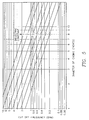
- Equation 9 the upper-cutoff frequency for the transmitting coil 112 is calculated as shown in Equation 9 (below).
- a inside radius of the casing 400 in meters
- ⁇ magnetic permeability of the fluid 408 (assumed to be 1)
- ⁇ relative permittivity of the fluid 408.
- Figure 5 illustrates the range of upper-cutoff frequencies for various casing sizes and dielectric permittivities.
- the lowest upper-cutoff frequency will occur when the tool 100 is completely surrounded with water, as shown in Figure 5. Since the permittivity of water is close to 80 dielectric units, and most North American casings have a diameter of about 5 inches, the chart of Figure 5 indicates that the lowest expected upper-cutoff frequency is about 300 MHz. Thus, to operate below upper-cutoff frequency in all cases, a frequency of less than 300 MHz should be used. However, if a larger casing size is used, a smaller operating frequency may be required, in accordance with Figure 5.
- the second transmitting coil 115 may be used to enhance the accuracy of the invention using a "borehole compensation technique," in accordance with the invention.
- the second transmitting coil 115 may be used to generate a magnetic field like that of the first transmitting coil 112, to be sensed by the receiving coils 113-114. Since the second transmitting coil 115 is located on the opposite side of the receiving coils 112-113 with respect to the first transmitting coil 112, the second transmitting coil 115 may be used to negate certain errors.
- errors may be reduced by operating the first and second transmitting coils 112, 115 sequentially, and then averaging the phase shift and attenuation detected by the receiving coils 113-114. This technique is helpful to reduce errors which might arise due to any temperature-dependent impedance characteristics of the receiving coils 113-114, or any errors arising in the electronics circuit 300.
- the first and second transmitting coils 112, 115 are operated repeatedly, in rapid, alternate succession.
- the mini-waveguides 200 are utilized to perform a number of functions. First of all, the waveguides 200 permit the magnetic fields from the transmitting coils 112, 115 to traverse the housing 106. In addition, the waveguides 200 are sized to sharply attenuate the electric fields from the transmitting coils 112, 115, thereby minimizing their effect upon the receiving coils 113-114, in accordance with the invention.
- the tool 100 of the present invention utilizes mini-waveguides 200 that are arranged in annular regions 202-205, and sized according to specific requirements as described below.
- the mini-waveguides 200 when sized according to the invention, allow axial and radial components of the magnetic fields and azimuthal electric fields associated with the transmitting coils 112, 115 to pass through with nominal attenuation, while severely attenuating the radial and circumferential components of the voltage-induced electric fields associated with the transmitting coils 112, 115. Due to the small dimensions of the mini-waveguides 200, each mini-waveguide 200 functions like a short section of waveguide, operated well below its upper-cutoff frequency.
- the annular regions 202-205 prevent the coils 112-115 from exciting or sensing undesired voltage-induced electric fields. This helps to avoid potential errors in the voltage signals induced on the receiving coils 113-114.
- a preferable size for each mini-waveguide is a thickness 212 of 0.093 inches, a width 208 of 0.031 inches, a spacing 214 of 0.031 inches, and a length 210 of 1.20 inches.
- the mini-waveguides 200 are preferably arranged longitudinally, i.e., with their length 210 parallel to the longitudinal axis 103.
- the production logging tool 100 of the present invention measures the amplitude attenuation and the phase shift between the receiving coils 113-114.
- An interpretation model is needed to convert this raw data into a value of water hold-up (Y w ).
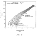
- the interpretation model may be generated using computer modeling, or by conducting actual tests of the tool 100 inside a casing 400 with different fluid mixtures. Such a model may be utilized to construct interpretative charts such as "spider web chart” and a "mixing law chart,” examples of which are shown in Figures 6-7 respectively.
- V R voltage in the receiving coil 113, in volts
- I T current in the transmitting coil 112, in amps
- ⁇ angular frequency of the excitation current (2 ⁇ x cycles/second)
- a radius of the coils 112-115, in meters
- b radius of the casing 400, in meters
- x i zeros of Bessel Function J1
- L spacing between the transmitting coil 112 and the receiving coil 113, in meters
- k complex wavenumber of the fluid 408, in meters ⁇ 1.
- the complex wavenumber (k) may be defined as shown in Equation 13 (below).
- F/m ⁇ r relative permittivity of the fluid 408, in dielectric units
- j ⁇ -1 ⁇
- R resistivity of fluid medium, in ⁇ -m.
- Equations 12-13 (above) are repeatedly used to calculate voltages on the receiving coils 112-113 for a wide range of electrical properties of different fluid 408.
- the complex voltages obtained using Equations 12-13 are then converted into phase shift and attenuation values for the receiving coils 113-114 using Equations 4-7 (above).
- the computer represents the relationship between phase shift, attenuation, apparent resistivity, and apparent permittivity in the form of a "spider web chart", such as Figure 6. Additional experiments are then conducted by varying the water's resistivity and the proportion of oil and water to establish a mixing law graph, such as Figure 7. Additionally, the relationship shown in Figure 7 may be represented as shown in Equation 14 (below).
- K a apparent relative permittivity of fluids in the casing 400, in dielectric units
- K w relative permittivity of water, corrected for temperature and pressure, in dielectric units
- K o relative permittivity of oil, corrected for temperature and pressure, in dielectric units
- R a apparent resistivity of fluids in the casing 400
- ⁇ -m apparent resistivity of water, in ⁇ -m
- M an empirically derived exponent, about 2.2.
- Equation 14 and Figure 7 interpolation between data points may be performed with a computer, as discussed above in relation to Figure 6.
- the use and application of mixing laws is generally discussed in Shen et al, Dielectric Properties of Reservoir Rocks at Ultra-High Frequencies , Geophysical, Vol. 50, No. 4 (April 1985) pp. 692-704, which is hereby incorporated by reference in its entirety.
- water hold-up (Y w ) may be established by a process known as "inversion”.
- the process of inversion involves utilizing an interpretation model (e.g. Figure 6) to obtain values for apparent resistivity and apparent permittivity, by plotting the phase shift and attenuation values obtained from the receiving coils 113-114.
- an interpretation model e.g. Figure 7 may be employed for values of water hold-up (Y w ) and water resistivity (R w ).
- mixing law graphs such as Figure 7 will depend upon the electrical properties of the oil and water in the casing 400.
- spider web charts such as Figure 6 will depend upon the design of the tool 100 and the dimensions of the casing 400.
- a production logging tool 100 was constructed in accordance with the invention and tested inside short lengths of steel casing.
- the mandrel 102 which was about 12 inches long, was sheathed inside a steel housing 106 of 1 11 16 inch diameter, equipped with annular regions 202-204. Only one transmitting coil 112 was used, spaced about 4 inches from the upper end of the mandrel 102.
- the first receiving coil 113 was spaced about 2 inches from the transmitting coil 112.
- the second receiving coil 114 was spaced 2 inches from the first receiving coil 113, 4 inches from the transmitting coil 112.
- Three different diameters of casing 400 were used, i.e., 5 1 2 , 6 5 8 , and 9 5 8 inches.
- the tool 100 inside a length of casing (not shown), was incorporated into a "flow loop" apparatus comprising a system of pumps and separator tanks to simulate a flowing oil well by circulating flows of oil and water at various rates.
- the water resistivity and salinity were varied by adding common salt (i.e., NaCl) to the circulating water.
- the measured phase shift and attenuation were interpreted using graphs such as Figures 6 and 7, and the results were compared to the water hold-up computed from the independently measured flow-rates of oil and water.
- the tool 100 was found to resolve water hold-up with an accuracy of 2-3% for a wide range of water salinities and oil-water ratios.
- the present invention provides its users with a number of advantages.
- the invention provides results that are typically sensitive to small changes in the depth of the tool 100.
- the invention operates in any level of water salinity, and may even be used to measure water salinity.
- the water resistivity as indicated by Figure 7, may be utilized in accordance with known formulas to yield water salinity. Such formulas, as are well known in the relevant art, depend primarily upon the value of temperature.
- one or more mixers may be utilized in conjunction with the invention.
- Such mixers may be deployed to create uniformity of the mixture in the casing 400.
- water hold-up and water cut may be substantially different, since water hold-up is an instantaneous measurement and water cut is measured over time.
- water and petroleum may be flowing at different rates inside the casing 400.
- mixers may be used to avoid any difference in water cut and water hold-up.
- mixers may be utilized to avoid measurement errors that might be introduced by bubbles that are greater than the spatial resolution of the tool 100.
- oil and water will tend to separate due to the difference in density and to the fundamentally immiscible nature of the liquids. This can lead to errors in the measurement if the dimensions of the bubbles of one liquid approach the spatial resolution of the tool 100.
- “powered” mixers may be used.
- the use of mixers for fluid mixing at the surface is known, for applications such as in oil field reservoirs.
- Powered mixers typically utilize motor-driven propellers to mix the fluid in the reservoir.
- "Static" (“motionless”) mixers repeatedly divide fluid flow with diverting vanes to mix flowing fluid. Although a static mixer adds no energy to the flow, it may cause a small pressure drop. Under either approach, the mixer may retract, collapse, or otherwise withdraw toward the outside of the tool string for storage.
- the housing 106 is connected to a hollow, cylindrical casing collar (not shown) having an inner cavity within which the housing 106 and mandrel 102 reside.
- the casing collar may be rigidly or flexibly attached to the housing in a manner sufficient to provide a cylindrical waveguide for electromagnetic signals generated by the transmitting coils 112,115.
- the outer diameter of the casing collar is slightly less than the inner diameter of the well casing, small enough to permit the casing collar to travel through the well casing without interference from any discontinuities on the well casing's inner surface.
- the casing collar's outer diameter and inner cavity are large enough to permit fluid 408 to freely pass through the casing collar, and around the housing 106.
- oil is also considered to include tar, methane, and other paraffin oils.
Landscapes
- Physics & Mathematics (AREA)
- Life Sciences & Earth Sciences (AREA)
- Electromagnetism (AREA)
- Engineering & Computer Science (AREA)
- Environmental & Geological Engineering (AREA)
- Geology (AREA)
- Remote Sensing (AREA)
- General Life Sciences & Earth Sciences (AREA)
- General Physics & Mathematics (AREA)
- Geophysics (AREA)
- Geophysics And Detection Of Objects (AREA)
Applications Claiming Priority (2)
| Application Number | Priority Date | Filing Date | Title |
|---|---|---|---|
| US08/131,077 US5453693A (en) | 1993-10-01 | 1993-10-01 | Logging system for measuring dielectric properties of fluids in a cased well using multiple mini-wave guides |
| US131077 | 1993-10-01 |
Publications (2)
| Publication Number | Publication Date |
|---|---|
| EP0646810A2 true EP0646810A2 (de) | 1995-04-05 |
| EP0646810A3 EP0646810A3 (de) | 1995-08-23 |
Family
ID=22447763
Family Applications (1)
| Application Number | Title | Priority Date | Filing Date |
|---|---|---|---|
| EP94301091A Withdrawn EP0646810A3 (de) | 1993-10-01 | 1994-02-16 | Messung der dielektrischen Eigenschaften von Bohrlochflüssigkeiten. |
Country Status (5)
| Country | Link |
|---|---|
| US (1) | US5453693A (de) |
| EP (1) | EP0646810A3 (de) |
| JP (1) | JPH07120411A (de) |
| CA (1) | CA2116513A1 (de) |
| NO (1) | NO940792L (de) |
Cited By (5)
| Publication number | Priority date | Publication date | Assignee | Title |
|---|---|---|---|---|
| EP0704717A3 (de) * | 1994-08-01 | 1998-02-25 | Baker Hughes Incorporated | Verfahren und Anordnung zur Abfrage eines Bohrlochs |
| EP0778474A3 (de) * | 1995-12-06 | 1999-11-24 | Integrated Drilling Services Limited | Widerstandsmessgerät für einen Bohrloch umgebenden geologischen Formationen |
| WO2001053855A1 (en) * | 2000-01-19 | 2001-07-26 | Baker Hughes Incorporated | Resistivity and dielectric constant well core measurement system for measurement while drilling and laboratory |
| GB2386191A (en) * | 2001-11-19 | 2003-09-10 | Schlumberger Holdings | Downhole measurement during production |
| CN105298489A (zh) * | 2015-12-03 | 2016-02-03 | 中国石油大学(华东) | 近井眼地层的介电常数频散特性在宽频谱的连续测量方法 |
Families Citing this family (38)
| Publication number | Priority date | Publication date | Assignee | Title |
|---|---|---|---|---|
| US5563512A (en) * | 1994-06-14 | 1996-10-08 | Halliburton Company | Well logging apparatus having a removable sleeve for sealing and protecting multiple antenna arrays |
| US5986749A (en) * | 1997-09-19 | 1999-11-16 | Cidra Corporation | Fiber optic sensing system |
| US6100696A (en) * | 1998-01-09 | 2000-08-08 | Sinclair; Paul L. | Method and apparatus for directional measurement of subsurface electrical properties |
| NO310383B1 (no) | 1998-06-18 | 2001-06-25 | Norske Stats Oljeselskap | Anordning og fremgangsmåte for detektering av elektriske egenskaper i en petroleumsbrönn ved hjelp av lededeelektromagnetiske bölger |
| US6483310B1 (en) | 1999-11-22 | 2002-11-19 | Scientific Drilling International | Retrievable, formation resistivity tool, having a slotted collar |
| US6445187B1 (en) | 2000-04-10 | 2002-09-03 | Jerry R. Montgomery | System for the measurement of electrical characteristics of geological formations from within steel cased wells using magnetic circuits |
| AUPQ729000A0 (en) * | 2000-05-03 | 2000-05-25 | Gropep Limited | Treatment of damaged connective tissue |
| NO313647B1 (no) * | 2000-05-15 | 2002-11-04 | Roxar Asa | Anordning for måling av egenskaper til en strömmende fluidblanding |
| AU2002330989A1 (en) * | 2001-08-03 | 2003-04-01 | Baker Hughes Incorporated | A method and apparatus for a multi-component induction instrumentmeasuring system |
| US6677756B2 (en) | 2001-08-03 | 2004-01-13 | Baker Hughes Incorporated | Multi-component induction instrument |
| US7463035B2 (en) * | 2002-03-04 | 2008-12-09 | Baker Hughes Incorporated | Method and apparatus for the use of multicomponent induction tool for geosteering and formation resistivity data interpretation in horizontal wells |
| US7719282B2 (en) * | 2004-04-14 | 2010-05-18 | Baker Hughes Incorporated | Method and apparatus for mulit-component induction instrument measuring system for geosteering and formation resistivity data interpretation in horizontal, vertical and deviated wells |
| US7436184B2 (en) * | 2005-03-15 | 2008-10-14 | Pathfinder Energy Services, Inc. | Well logging apparatus for obtaining azimuthally sensitive formation resistivity measurements |
| US7414405B2 (en) * | 2005-08-02 | 2008-08-19 | Pathfinder Energy Services, Inc. | Measurement tool for obtaining tool face on a rotating drill collar |
| US7587290B2 (en) * | 2006-06-15 | 2009-09-08 | Phase Dynamics, Inc. | High water cut well measurements using heuristic salinity determination |
| WO2007149106A1 (en) * | 2006-06-19 | 2007-12-27 | Halliburton Energy Services, Inc. | Antenna cutout in a downhole tubular |
| US7742008B2 (en) * | 2006-11-15 | 2010-06-22 | Baker Hughes Incorporated | Multipole antennae for logging-while-drilling resistivity measurements |
| US7558675B2 (en) * | 2007-07-25 | 2009-07-07 | Smith International, Inc. | Probablistic imaging with azimuthally sensitive MWD/LWD sensors |
| US8008919B2 (en) * | 2008-03-25 | 2011-08-30 | Baker Hughes Incorporated | Method for compensating drill pipe and near-borehole effect on and electronic noise in transient resistivity measurements |
| US8230934B2 (en) * | 2009-10-02 | 2012-07-31 | Baker Hughes Incorporated | Apparatus and method for directionally disposing a flexible member in a pressurized conduit |
| US8536883B2 (en) | 2010-04-29 | 2013-09-17 | Schlumberger Technology Corporation | Method of measuring a multiphase flow |
| US8600115B2 (en) | 2010-06-10 | 2013-12-03 | Schlumberger Technology Corporation | Borehole image reconstruction using inversion and tool spatial sensitivity functions |
| US9658360B2 (en) | 2010-12-03 | 2017-05-23 | Schlumberger Technology Corporation | High resolution LWD imaging |
| US8839856B2 (en) | 2011-04-15 | 2014-09-23 | Baker Hughes Incorporated | Electromagnetic wave treatment method and promoter |
| US9429012B2 (en) * | 2013-05-07 | 2016-08-30 | Saudi Arabian Oil Company | Downhole salinity measurement |
| CN103590809A (zh) * | 2013-10-26 | 2014-02-19 | 中国石油化工集团公司 | 瞬变电磁测井激励方法 |
| CN103643951B (zh) * | 2013-12-16 | 2017-05-31 | 西南石油大学 | 一种高分辨率双电双感应测井仪器与方法 |
| ES2729345T3 (es) * | 2014-05-13 | 2019-10-31 | Bauer Maschinen Gmbh | Dispositivo de perforación submarino y procedimiento para obtener y analizar muestras de fondo de un fondo de masa de agua |
| US9910182B2 (en) * | 2014-07-02 | 2018-03-06 | Baker Hughes, A Ge Company, Llc | Method and apparatus for inversion in dielectric logging |
| CN104594890B (zh) * | 2015-01-15 | 2017-08-29 | 燕山大学 | 一种用于水平井动态全水值测量取样槽 |
| US10767470B2 (en) | 2015-08-20 | 2020-09-08 | Halliburton Energy Services, Inc. | Inspection of wellbore conduits using a distributed sensor system |
| US9909415B2 (en) | 2015-11-20 | 2018-03-06 | Cameron International Corporation | Method and apparatus for analyzing mixing of a fluid in a conduit |
| GB2564209B (en) * | 2017-04-26 | 2020-02-26 | Tracto Technik | Drill head comprising a transmitter which transmits a radio signal using a direct digital synthesizer |
| US10859486B2 (en) | 2017-05-26 | 2020-12-08 | General Electric Co. | Systems and method for down-hole phase monitoring |
| WO2020005217A1 (en) * | 2018-06-27 | 2020-01-02 | Schlumberger Technology Corporation | Apparatus for measuring multiphase fluid flows and related methods |
| CN110700811B (zh) * | 2019-10-29 | 2023-04-07 | 北京工商大学 | 油井含水率及流量的波导相位测量方法及装置 |
| CN119616467A (zh) * | 2023-09-13 | 2025-03-14 | 中国石油天然气集团有限公司 | 基于阻抗表征的随钻地层出水监测工具及监测方法 |
| US20260063820A1 (en) * | 2024-08-29 | 2026-03-05 | Schlumberger Technology Corporation | Em logging tool employing wire tube interference mitigation |
Family Cites Families (41)
| Publication number | Priority date | Publication date | Assignee | Title |
|---|---|---|---|---|
| US3675121A (en) * | 1970-06-26 | 1972-07-04 | Chevron Res | Dielectric constant measurement method |
| US3849721A (en) * | 1973-08-23 | 1974-11-19 | Schlumberger Technology Corp | Microwave logging apparatus having dual processing channels |
| US4292588A (en) * | 1978-12-18 | 1981-09-29 | Schlumberger Technology Corporation | Electromagnetic inspection tool for ferromagnetic casings |
| FR2492540A1 (fr) * | 1980-10-17 | 1982-04-23 | Schlumberger Prospection | Dispositif pour diagraphie electromagnetique dans les forages |
| US4503383A (en) * | 1982-01-07 | 1985-03-05 | Agar Corporation, N.V. | Device for detecting an interface between two fluids |
| US4536714A (en) * | 1982-04-16 | 1985-08-20 | Schlumberger Technology Corporation | Shields for antennas of borehole logging devices |
| USRE32913E (en) * | 1982-04-16 | 1989-04-25 | Schlumberger Technology Corp. | Shields for antennas of borehole logging devices |
| US4441362A (en) * | 1982-04-19 | 1984-04-10 | Dresser Industries, Inc. | Method for determining volumetric fractions and flow rates of individual phases within a multi-phase flow regime |
| US4499418A (en) * | 1982-08-05 | 1985-02-12 | Texaco Inc. | Water cut monitoring means and method |
| US4581584A (en) * | 1984-02-03 | 1986-04-08 | Mobil Oil Corporation | Microwave electromagnetic borehole dipmeter |
| GB8426246D0 (en) * | 1984-10-17 | 1984-11-21 | British Gas Corp | Microwave reflection survey equipment |
| GB2166599B (en) * | 1984-11-02 | 1988-06-08 | Coal Ind | Borehole located directional antennae means for electromagnetic sensing systems |
| US4689572A (en) * | 1984-12-28 | 1987-08-25 | Schlumberger Technology Corp. | Electromagnetic logging apparatus with slot antennas |
| US4673899A (en) * | 1985-09-23 | 1987-06-16 | General Electric Company | H-plane stacked waveguide power divider/combiner |
| US5006785A (en) * | 1986-04-23 | 1991-04-09 | Chevron Research Company | Microwave oil saturation scanner |
| US4774680B1 (en) * | 1986-09-19 | 1993-10-12 | Agar Corporation Ltd. | Method and apparatus for net oil measurement |
| US4996490A (en) * | 1986-11-18 | 1991-02-26 | Atlantic Richfield Company | Microwave apparatus and method for measuring fluid mixtures |
| US4862060A (en) * | 1986-11-18 | 1989-08-29 | Atlantic Richfield Company | Microwave apparatus for measuring fluid mixtures |
| US4902961A (en) * | 1987-04-08 | 1990-02-20 | Chevron Research Company | Microwave system for monitoring water content in a petroleum pipeline |
| GB8721858D0 (en) * | 1987-09-17 | 1987-10-21 | Schlumberger Ltd | Measurement apparatus |
| US4899112A (en) * | 1987-10-30 | 1990-02-06 | Schlumberger Technology Corporation | Well logging apparatus and method for determining formation resistivity at a shallow and a deep depth |
| US5014011A (en) * | 1988-05-31 | 1991-05-07 | Ford Motor Company | Capacitance measuring apparatus with means for nulling the resistive component |
| FR2637089B1 (fr) * | 1988-09-29 | 1990-11-30 | Schlumberger Prospection | Procede et dispositif pour l'analyse d'un ecoulement a plusieurs phases dans un puits d'hydrocarbures |
| GB2227841B (en) * | 1988-12-03 | 1993-05-12 | Schlumberger Ltd | Impedance cross correlation logging tool |
| US4947129A (en) * | 1988-12-05 | 1990-08-07 | Texaco Inc. | Petroleum stream microwave watercut monitor |
| US4947128A (en) * | 1989-02-23 | 1990-08-07 | Texaco Ijn Inc | Co-variance microwave water cut monitoring means and method |
| US4947127A (en) * | 1989-02-23 | 1990-08-07 | Texaco Inc. | Microwave water cut monitor |
| US4996489A (en) * | 1989-03-31 | 1991-02-26 | Halliburton Logging Services, Inc. | Laboratory technique for measuring complex dielectric constant of rock core samples |
| US5014010A (en) * | 1989-04-10 | 1991-05-07 | Texaco Inc. | Dual frequency microwave water cut monitoring means and method |
| US5001434A (en) * | 1989-04-10 | 1991-03-19 | Texaco Inc. | Variable mode microwave water cut monitor and method |
| FR2649793B1 (fr) * | 1989-07-11 | 1993-09-03 | Aerospatiale | Capteur coaxial micro-onde et chaine de mesure comprenant ce capteur pour la mesure en continu de la viscosite d'un milieu visqueux |
| US4980642A (en) * | 1990-04-20 | 1990-12-25 | Baroid Technology, Inc. | Detection of influx of fluids invading a borehole |
| US5132903A (en) * | 1990-06-19 | 1992-07-21 | Halliburton Logging Services, Inc. | Dielectric measuring apparatus for determining oil and water mixtures in a well borehole |
| GB2246866A (en) * | 1990-08-06 | 1992-02-12 | Texaco Development Corp | Borehole water content logging system and method |
| US5083089A (en) * | 1991-02-20 | 1992-01-21 | Spatial Dynamics, Ltd. | Fluid mixture ratio monitoring method and apparatus |
| FR2675202A1 (fr) * | 1991-04-11 | 1992-10-16 | Schlumberger Services Petrol | Procede pour determiner localement la nature d'une phase dans un fluide triphasique en mouvement et application de ce procede a la determination de parametres d'ecoulement du fluide. |
| US5210492A (en) * | 1991-04-22 | 1993-05-11 | Tokyo Gas Co., Ltd. | Remote field eddy current flaw detector for metal pipes having a pair of receiver coils providing a differential offset amplitude signal |
| US5157331A (en) * | 1991-10-04 | 1992-10-20 | Western Atlas International, Inc. | Enhanced wide aperture groove for antenna of downhole resistivity tool |
| US5331284A (en) * | 1992-04-21 | 1994-07-19 | Baker Hughes Incorporated | Meter and method for in situ measurement of the electromagnetic properties of various process materials using cutoff frequency characterization and analysis |
| US5329235A (en) * | 1992-11-02 | 1994-07-12 | Western Atlas International, Inc. | Method for processing signals from an MWD electromagnetic resistivity logging tool |
| US5341100A (en) * | 1992-12-22 | 1994-08-23 | Western Atlas International, Inc. | Electromagnetic wave method and apparatus for downhole measurement of fluid conductivity and hydrocarbon volume during formation testing |
-
1993
- 1993-10-01 US US08/131,077 patent/US5453693A/en not_active Expired - Fee Related
-
1994
- 1994-02-16 EP EP94301091A patent/EP0646810A3/de not_active Withdrawn
- 1994-02-25 CA CA002116513A patent/CA2116513A1/en not_active Abandoned
- 1994-03-07 NO NO940792A patent/NO940792L/no unknown
- 1994-03-11 JP JP6067693A patent/JPH07120411A/ja active Pending
Cited By (10)
| Publication number | Priority date | Publication date | Assignee | Title |
|---|---|---|---|---|
| EP0704717A3 (de) * | 1994-08-01 | 1998-02-25 | Baker Hughes Incorporated | Verfahren und Anordnung zur Abfrage eines Bohrlochs |
| US6288548B1 (en) | 1994-08-01 | 2001-09-11 | Baker Hughes Incorporated | Method and apparatus for making electromagnetic induction measurements through a drill collar |
| EP0778474A3 (de) * | 1995-12-06 | 1999-11-24 | Integrated Drilling Services Limited | Widerstandsmessgerät für einen Bohrloch umgebenden geologischen Formationen |
| WO2001053855A1 (en) * | 2000-01-19 | 2001-07-26 | Baker Hughes Incorporated | Resistivity and dielectric constant well core measurement system for measurement while drilling and laboratory |
| GB2377761A (en) * | 2000-01-19 | 2003-01-22 | Baker Hughes Inc | Resistivity and dielectric constant well core measurement system for measurement while drilling and laboratory |
| GB2377761B (en) * | 2000-01-19 | 2004-06-23 | Baker Hughes Inc | Resistivity and dielectric constant well core measurement system for measurement while drilling |
| GB2386191A (en) * | 2001-11-19 | 2003-09-10 | Schlumberger Holdings | Downhole measurement during production |
| GB2386191B (en) * | 2001-11-19 | 2004-07-21 | Schlumberger Holdings | Downhole measurement apparatus and technique |
| CN105298489A (zh) * | 2015-12-03 | 2016-02-03 | 中国石油大学(华东) | 近井眼地层的介电常数频散特性在宽频谱的连续测量方法 |
| CN105298489B (zh) * | 2015-12-03 | 2017-12-19 | 中国石油大学(华东) | 近井眼地层的介电常数频散特性在宽频谱的连续测量方法 |
Also Published As
| Publication number | Publication date |
|---|---|
| JPH07120411A (ja) | 1995-05-12 |
| CA2116513A1 (en) | 1995-04-02 |
| EP0646810A3 (de) | 1995-08-23 |
| NO940792D0 (no) | 1994-03-07 |
| NO940792L (no) | 1994-10-03 |
| US5453693A (en) | 1995-09-26 |
Similar Documents
| Publication | Publication Date | Title |
|---|---|---|
| US5453693A (en) | Logging system for measuring dielectric properties of fluids in a cased well using multiple mini-wave guides | |
| EP0462803B1 (de) | Verfahren und Apparat zur Bestimmung von Öl/Wasser-Mischungen in einem Bohrloch | |
| US5672971A (en) | Well logging system arranged for stable, high-sensitivity reception of propagating electromagnetic waves | |
| US6788066B2 (en) | Method and apparatus for measuring resistivity and dielectric in a well core in a measurement while drilling tool | |
| EP0105801B1 (de) | Verwendung der transversalen magnetischen Komponente in einem Bohrlochmessgerät | |
| US4451789A (en) | Logging tool and method for measuring resistivity of different radial zones at a common depth of measurement | |
| EA005307B1 (ru) | Устройство для точного измерения характеристик пласта | |
| US7639016B2 (en) | Downhole multi-phase flow imager | |
| CA2559119A1 (en) | Method for determining properties of earth formations using dielectric permittivity measurements | |
| Liu | Theory of electromagnetic well logging | |
| US7714585B2 (en) | Multi-frequency cancellation of dielectric effect | |
| US10209390B2 (en) | Measuring fluid conductivity | |
| US20090102485A1 (en) | Methods for Interpreting Multi-Component Induction Logs Using the X-Signal Measurements | |
| US4916400A (en) | Method for determining characteristics of the interior geometry of a wellbore | |
| US20080157773A1 (en) | Method and Apparatus for Use of the Real Component of a Magnetic Field of Multicomponent Resistivity Measurements | |
| RU2326414C1 (ru) | Способ для использования прибора многокомпонентного индукционного каротажа при управлении параметрами бурения и при интерпретации результатов измерений удельного электрического сопротивления в горизонтальных скважинах | |
| US7336080B2 (en) | Method and apparatus for use of the real component of a magnetic field of multicomponent resistivity measurements | |
| US12360278B2 (en) | Quantification of formation water saturation and salinity using relative permittivity and conductivity measurements | |
| Shen | Theory of a coil-type resistivity sensor for MWD application | |
| CN113756791A (zh) | 随钻测量电阻率的装置和方法 | |
| Huchital et al. | The deep propagation tool (a new electromagnetic logging tool) | |
| US2719948A (en) | Magnetically investigating material at the wall of a well bore | |
| CA2397916C (en) | Resistivity and dielectric constant well core measurement system for measurement while drilling and laboratory | |
| Segesman et al. | Well logging-The exploration of subsurface geology | |
| US20080252295A1 (en) | Detection of Borehole Effects Due to Eccentricity on Induction Instruments with Tilted Transducers |
Legal Events
| Date | Code | Title | Description |
|---|---|---|---|
| PUAI | Public reference made under article 153(3) epc to a published international application that has entered the european phase |
Free format text: ORIGINAL CODE: 0009012 |
|
| AK | Designated contracting states |
Kind code of ref document: A2 Designated state(s): DE FR GB IT NL |
|
| PUAL | Search report despatched |
Free format text: ORIGINAL CODE: 0009013 |
|
| AK | Designated contracting states |
Kind code of ref document: A3 Designated state(s): DE FR GB IT NL |
|
| 17P | Request for examination filed |
Effective date: 19951017 |
|
| 17Q | First examination report despatched |
Effective date: 19970415 |
|
| 18D | Application deemed to be withdrawn |
Effective date: 19970826 |