EP0647497A2 - Procédé d'alliage d'une pièce à usiner utilisant le rayonnement laser - Google Patents
Procédé d'alliage d'une pièce à usiner utilisant le rayonnement laser Download PDFInfo
- Publication number
- EP0647497A2 EP0647497A2 EP94115659A EP94115659A EP0647497A2 EP 0647497 A2 EP0647497 A2 EP 0647497A2 EP 94115659 A EP94115659 A EP 94115659A EP 94115659 A EP94115659 A EP 94115659A EP 0647497 A2 EP0647497 A2 EP 0647497A2
- Authority
- EP
- European Patent Office
- Prior art keywords
- fuel gas
- workpiece
- carbon
- gas mixture
- laser
- Prior art date
- Legal status (The legal status is an assumption and is not a legal conclusion. Google has not performed a legal analysis and makes no representation as to the accuracy of the status listed.)
- Granted
Links
Images

Classifications
-
- B—PERFORMING OPERATIONS; TRANSPORTING
- B23—MACHINE TOOLS; METAL-WORKING NOT OTHERWISE PROVIDED FOR
- B23K—SOLDERING OR UNSOLDERING; WELDING; CLADDING OR PLATING BY SOLDERING OR WELDING; CUTTING BY APPLYING HEAT LOCALLY, e.g. FLAME CUTTING; WORKING BY LASER BEAM
- B23K26/00—Working by laser beam, e.g. welding, cutting or boring
- B23K26/34—Laser welding for purposes other than joining
-
- B—PERFORMING OPERATIONS; TRANSPORTING
- B23—MACHINE TOOLS; METAL-WORKING NOT OTHERWISE PROVIDED FOR
- B23K—SOLDERING OR UNSOLDERING; WELDING; CLADDING OR PLATING BY SOLDERING OR WELDING; CUTTING BY APPLYING HEAT LOCALLY, e.g. FLAME CUTTING; WORKING BY LASER BEAM
- B23K35/00—Rods, electrodes, materials, or media, for use in soldering, welding, or cutting
- B23K35/22—Rods, electrodes, materials, or media, for use in soldering, welding, or cutting characterised by the composition or nature of the material
- B23K35/36—Selection of non-metallic compositions, e.g. coatings or fluxes; Selection of soldering or welding materials, conjoint with selection of non-metallic compositions, both selections being of interest
- B23K35/365—Selection of non-metallic compositions of coating materials either alone or conjoint with selection of soldering or welding materials
-
- B—PERFORMING OPERATIONS; TRANSPORTING
- B23—MACHINE TOOLS; METAL-WORKING NOT OTHERWISE PROVIDED FOR
- B23K—SOLDERING OR UNSOLDERING; WELDING; CLADDING OR PLATING BY SOLDERING OR WELDING; CUTTING BY APPLYING HEAT LOCALLY, e.g. FLAME CUTTING; WORKING BY LASER BEAM
- B23K35/00—Rods, electrodes, materials, or media, for use in soldering, welding, or cutting
- B23K35/22—Rods, electrodes, materials, or media, for use in soldering, welding, or cutting characterised by the composition or nature of the material
- B23K35/38—Selection of media, e.g. special atmospheres for surrounding the working area
-
- C—CHEMISTRY; METALLURGY
- C22—METALLURGY; FERROUS OR NON-FERROUS ALLOYS; TREATMENT OF ALLOYS OR NON-FERROUS METALS
- C22F—CHANGING THE PHYSICAL STRUCTURE OF NON-FERROUS METALS AND NON-FERROUS ALLOYS
- C22F1/00—Changing the physical structure of non-ferrous metals or alloys by heat treatment or by hot or cold working
- C22F1/02—Changing the physical structure of non-ferrous metals or alloys by heat treatment or by hot or cold working in inert or controlled atmosphere or vacuum
-
- C—CHEMISTRY; METALLURGY
- C22—METALLURGY; FERROUS OR NON-FERROUS ALLOYS; TREATMENT OF ALLOYS OR NON-FERROUS METALS
- C22F—CHANGING THE PHYSICAL STRUCTURE OF NON-FERROUS METALS AND NON-FERROUS ALLOYS
- C22F3/00—Changing the physical structure of non-ferrous metals or alloys by special physical methods, e.g. treatment with neutrons
-
- B—PERFORMING OPERATIONS; TRANSPORTING
- B23—MACHINE TOOLS; METAL-WORKING NOT OTHERWISE PROVIDED FOR
- B23K—SOLDERING OR UNSOLDERING; WELDING; CLADDING OR PLATING BY SOLDERING OR WELDING; CUTTING BY APPLYING HEAT LOCALLY, e.g. FLAME CUTTING; WORKING BY LASER BEAM
- B23K35/00—Rods, electrodes, materials, or media, for use in soldering, welding, or cutting
- B23K35/22—Rods, electrodes, materials, or media, for use in soldering, welding, or cutting characterised by the composition or nature of the material
- B23K35/24—Selection of soldering or welding materials proper
- B23K35/30—Selection of soldering or welding materials proper with the principal constituent melting at less than 1550°C
- B23K35/3053—Fe as the principal constituent
- B23K35/306—Fe as the principal constituent with C as next major constituent, e.g. cast iron
Definitions
- the invention relates to a method for machining a workpiece using laser radiation, carbon being essentially used as the alloying element.
- the graphite coating is mostly applied manually by means of graphite sprays or by applying liquids containing graphite to the workpiece surface.
- the known coatings have disadvantages. With sprayed or brushed graphite coatings, it is only possible to achieve constant layer thicknesses with great effort. The application of the graphite coatings is difficult to automate.
- the spray and liquid apart from graphite, the spray and liquid contain metallurgically undesirable accompanying substances (for example additives that increase adhesion), which adversely affect the machining result.
- the solvents contained in the spray and liquid also cause environmental pollution.
- Another disadvantage is that the removal of non-irradiated coatings is very expensive. For this reason, coating with graphite for laser beam alloying has not become established in industrial applications.
- Laser beam alloying from the gas phase initially requires complex gas routing.
- the amount of carbon that can be introduced with this method is relatively small. Problems arise in laser beam alloying due to contamination of the gas by air whirled into the gas jet.
- There is also a disadvantage of the carbon supply from the gas phase in that the carbon must not be used in pure form, but as CO2, C2H4 or similar organic gases. Such quantities of hydrogen and oxygen can have a negative impact on the quality of the alloy.
- the invention is based on the object of demonstrating a method of the type described in the introduction, wherein when a carbon coating is applied, a constant layer thickness of the coating and thus a uniform alloying are ensured, but at the same time the disadvantages of the known methods described are to be avoided. In particular, undesired components should be kept away from the workpiece surface.
- This object is achieved in that an organic, flammable gas or gas mixture is burned, that the alloy coating is formed on the workpiece surface by addition of the carbon particles produced during the combustion and that the carbon is at least partially introduced into the melt generated by the laser beam and thus the workpiece is alloyed at the coated and laser-irradiated areas.
- the coating of workpieces with carbon according to the invention for another purpose is known from an unrelated technical field, namely from the glass industry.
- a method for coating molds for hollow glass production is described in order to ensure a residue-free separation of mold and glass to reach.
- the application of a carbon coating under the name CARBOFLAM® is based on burning a flame from acetylene / air or acetylene / oxygen.
- Carrying out the method according to the invention leads to the application of a uniform carbon layer on the workpiece surface to be coated.
- the carbon layer is produced reproducibly. Additional advantages result from the fact that the carbon layer can be easily removed again after the laser processing of the surface of the workpiece which has not been processed with the laser.
- the carbon layer applied according to the invention has very little contamination in comparison with conventional processes, so that no unwanted material changes occur on the workpiece due to the coating for the laser beam alloying.
- the use of solvents and additives which increase adhesion can be dispensed with.
- the combustion flame of the fuel gas or fuel gas mixture is advantageously directed onto the surface to be coated by means of a burner.
- This makes it possible to produce a constant layer thickness of the attached carbon layer, the coating taking place independently of the position and geometry of the workpiece to be machined.
- a value between 50 and 500 mm, preferably 50 to 200 mm, has proven itself as the distance between the burner and the surface of the workpiece to be coated.
- Acetylene is advantageously used as the organic, combustible gas (fuel gas), optionally mixed with other organic fuel gases.
- the carbon particles generated during the combustion of the organic fuel gas contain up to 1 to 3% by weight of hydrogen in addition to carbon.
- Carbon layers obtained from the combustion of acetylene are characterized by a very high level of purity. They consist of over 99% pure carbon.
- the average particle size is approximately 40 to 50 nm, the particle size ranging approximately from 5 to 250 nm.
- the carbon particles formed during the combustion of the organic fuel gas are composed of a large number of small crystals with a size of 2 to 3 nm.
- the crystals in turn consist of a series of graphitic layers (usually 3 to 5 layers), which then form an approximately spherical shape of the particles.
- the carbon layer is applied directly to the surface of the workpiece to be coated by the flame in which the carbon particles form.
- the flame should burn tightly, but not turbulently, since ambient air is whirled up in turbulent flames, which has a negative effect on the formation of the carbon particles.
- the layers themselves are parallel to each other. Each can contain 30 carbon six-membered rings. In contrast to graphite, the C-6-rings are irregularly shifted against each other.
- the lattice constants of the carbon crystals formed in the process according to the invention also differ significantly from those for pure graphite.
- the carbon particles formed in a pure acetylene flame are black-brown. This means that the coating has a high absorption capacity for the laser radiation.
- a fuel gas mixture can be used which, in addition to the organic fuel gas, contains an oxygen-containing gas such as air, oxygen-enriched air or pure oxygen.
- a fuel gas mixture of acetylene and oxygen forms a deep black and well adhering carbon layer.
- a fuel gas mixture with an oxygen content of 1 to 5 mol% is suitable.
- a fuel gas mixture which contains between 5 and 10% by volume of air has proven itself in tests.
- a sheath flow burner is preferably used in which the acetylene flame is enveloped and supported by a flowing air jacket.
- the coating of the workpiece surface to be machined according to the invention can be carried out spatially and temporally separately from the laser beam alloying in a separate working step or immediately before the laser machining in an integrated working step.
- the laser beam system for laser processing is usually CNC-controlled (Computerized Numerical Control).
- the control of the burner can therefore advantageously be coupled with the control of the laser processing system, the CNC also taking over the control of the burner for carbon coating.
- a torch adapted to the contour of the workpiece is used.
- the shape of the burner opening is varied, for example by round, elliptical or slit-shaped burner openings. Thereby uniform and complete coating of the workpiece surfaces to be machined with the laser is ensured.
- Covers and masks can be used to achieve a coating with any geometric shape on the workpiece surface. In this way it can be achieved that only the surfaces are coated with carbon, which are then also processed with the laser. Since no carbon is deposited on workpiece surfaces that are not subsequently processed with the laser, reworking of the workpiece can be omitted in which the workpiece surface is cleaned of the carbon coating after the laser processing.
- FIG. 1 shows a workpiece 1 whose workpiece surface is to be subjected to an alloy with carbon.
- Acetylene 2 is fed to a burner 3 as fuel gas.
- oxygen or air is passed into the burner 3 as the gas 4 containing oxygen.
- the fuel gas mixture thus formed burns in the flames 5, carbon particles being formed.
- These carbon particles are carried onto the workpiece surface via the burner flames 5 and form an alloy coating 6 on the workpiece surface.
- the focused or defocused laser beam 7 strikes the coated workpiece surface 6, where a large part of its energy is absorbed due to the coating 6. As a result, the workpiece is melted in the irradiated area. This process results in an alloyed metal workpiece after cooling and solidification. Since that If the workpiece is moved by the set feed according to the direction of the arrow shown, the processed and alloyed surface 8 results from the coating and laser irradiation.
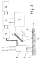
- FIG. 2 illustrates the integration of the coating according to the invention with direct processing by the laser beam from FIG. 1 in the control of the overall system.
- the laser radiation 7 is thrown from the laser 9 onto the coated workpiece surface 6 via a beam guide 10, which is shown in simplified form.
- the laser 9 interacts with the machine control 11, which in turn, symbolized by reciprocal arrows, interacts with both the processing system 12 and the burner control 13.
- the burner control 13 is connected directly to the burner 3.
- the burner 3 can be used in a clocked manner. In the pauses, i.e. if the carbon particle formation is to be reduced, the proportion of the fuel gas 2 in the fuel gas mixture can be reduced or the amount of the oxygen-containing gas 4 added can be increased.
Landscapes
- Chemical & Material Sciences (AREA)
- Engineering & Computer Science (AREA)
- Mechanical Engineering (AREA)
- Physics & Mathematics (AREA)
- Optics & Photonics (AREA)
- Crystallography & Structural Chemistry (AREA)
- Materials Engineering (AREA)
- Metallurgy (AREA)
- Organic Chemistry (AREA)
- Thermal Sciences (AREA)
- Plasma & Fusion (AREA)
- Laser Beam Processing (AREA)
- Electrical Discharge Machining, Electrochemical Machining, And Combined Machining (AREA)
Applications Claiming Priority (2)
| Application Number | Priority Date | Filing Date | Title |
|---|---|---|---|
| DE4334409 | 1993-10-08 | ||
| DE4334409A DE4334409A1 (de) | 1993-10-08 | 1993-10-08 | Verfahren zum Legieren eines Werkstückes unter Einsatz von Laserstrahlung |
Publications (3)
| Publication Number | Publication Date |
|---|---|
| EP0647497A2 true EP0647497A2 (fr) | 1995-04-12 |
| EP0647497A3 EP0647497A3 (fr) | 1996-10-02 |
| EP0647497B1 EP0647497B1 (fr) | 1997-06-18 |
Family
ID=6499753
Family Applications (1)
| Application Number | Title | Priority Date | Filing Date |
|---|---|---|---|
| EP94115659A Expired - Lifetime EP0647497B1 (fr) | 1993-10-08 | 1994-10-05 | Procédé d'alliage d'une pièce à usiner utilisant le rayonnement laser |
Country Status (4)
| Country | Link |
|---|---|
| EP (1) | EP0647497B1 (fr) |
| AT (1) | ATE154535T1 (fr) |
| CZ (1) | CZ286028B6 (fr) |
| DE (2) | DE4334409A1 (fr) |
Families Citing this family (1)
| Publication number | Priority date | Publication date | Assignee | Title |
|---|---|---|---|---|
| DE19931948B4 (de) * | 1999-07-09 | 2004-11-11 | Zwilling J. A. Henckels Ag | Verfahren zur Herstellung einer Klinge eines Schneidwerkzeuges und damit hergestelltes Erzeugnis |
Family Cites Families (1)
| Publication number | Priority date | Publication date | Assignee | Title |
|---|---|---|---|---|
| BE714641A (fr) * | 1968-05-03 | 1968-09-30 |
-
1993
- 1993-10-08 DE DE4334409A patent/DE4334409A1/de not_active Withdrawn
-
1994
- 1994-10-05 AT AT94115659T patent/ATE154535T1/de not_active IP Right Cessation
- 1994-10-05 DE DE59403173T patent/DE59403173D1/de not_active Expired - Fee Related
- 1994-10-05 EP EP94115659A patent/EP0647497B1/fr not_active Expired - Lifetime
- 1994-10-07 CZ CZ942478A patent/CZ286028B6/cs not_active IP Right Cessation
Also Published As
| Publication number | Publication date |
|---|---|
| CZ247894A3 (en) | 1995-08-16 |
| DE59403173D1 (de) | 1997-07-24 |
| DE4334409A1 (de) | 1995-04-13 |
| ATE154535T1 (de) | 1997-07-15 |
| EP0647497B1 (fr) | 1997-06-18 |
| CZ286028B6 (cs) | 1999-12-15 |
| EP0647497A3 (fr) | 1996-10-02 |
Similar Documents
| Publication | Publication Date | Title |
|---|---|---|
| DE102005005359B4 (de) | Verfahren zum Kaltgasspritzen | |
| DE102012212954B4 (de) | Kaltgesprühte und wärmebehandelte Beschichtung für Magnesium | |
| DE10218563B4 (de) | Verfahren zur Ventilsitz-Herstellung unter Verwendung eines Laserplattierprozesses | |
| EP0915184B1 (fr) | Procédé de fabrication d'une couche de céramique sur un substrat métallique | |
| DE112014005068T5 (de) | Unterhalb der Oberfläche stattfindende Laserbearbeitung einer Wirbelschicht | |
| DE3506302C2 (fr) | ||
| DE2523435C2 (de) | Verfahren und Vorrichtungen zum Plasma-Flammspritzen | |
| DE112014003541T5 (de) | Reparatur eines Substrats mit von einer Komponente gestütztem Zusatzwerkstoff | |
| DE3784548T2 (de) | Verfahren zum Aufbringen von Überzügen hoher Qualität und komplexer Geometrie durch Plasmaspritzen. | |
| DE102016223987A1 (de) | Verfahren zur Herstellung eines Bauteils mit Kavitäten und/oder Hinterschneidungen | |
| DE69512369T2 (de) | Verfahren, vorrichtung und anlage zum beschichten von rohren, insbesondere pipelinen | |
| DE3913687C2 (fr) | ||
| EP3323597B1 (fr) | Dispositif et procédé de fabrication additive d'un produit tridimensionnel | |
| DE4236911C1 (de) | Thermisches Spritzverfahren zur Erzeugung von Oberflächenbeschichtungen | |
| EP0647497B1 (fr) | Procédé d'alliage d'une pièce à usiner utilisant le rayonnement laser | |
| DE102014208435A1 (de) | Anordnung und Verfahren zum schichtweisen Erstellen einer Auftragschicht | |
| EP0263469B1 (fr) | Procédé pour l'enduction thermique de surfaces | |
| DE69313980T2 (de) | Verfahren zum Auftragschweissen an einem Werkstück mittels Plasma mit übertragenem Lichtbogen | |
| CH414891A (de) | Verfahren zum Schneiden von Werkstücken mittels eines Ladungsträgerstrahls | |
| DE69025827T2 (de) | Rostfreier korrosionsfester Stahl | |
| EP0647498B1 (fr) | Procédé d'usinage d'une pièce, utilisant le rayonnement laser avec augmentation du degré d'absorption de la surface de la pièce | |
| EP3473749B1 (fr) | Procédé d'application d'une couche sur un composant et composant fabriqué selon ledit procédé | |
| DE102013202483B4 (de) | Verfahren und Maschine zur Herstellung einer Oberflächenbeschichtung | |
| DE4141317C1 (en) | Prodn. of wear-reducing coating to reduce cracking and distortion - for screw surface in e.g. plastic extruder comprises introducing molybdenum@-contg. material into laser beam and depositing on steel body | |
| DE102017208659A1 (de) | Verwendung von Pulverschläuchen zum Zuführen von Lotmischungen bei der generativen Herstellung von Bauteilen mittels Laserauftragschweißen |
Legal Events
| Date | Code | Title | Description |
|---|---|---|---|
| PUAI | Public reference made under article 153(3) epc to a published international application that has entered the european phase |
Free format text: ORIGINAL CODE: 0009012 |
|
| AK | Designated contracting states |
Kind code of ref document: A2 Designated state(s): AT BE CH DE ES FR GB IT LI NL |
|
| PUAL | Search report despatched |
Free format text: ORIGINAL CODE: 0009013 |
|
| AK | Designated contracting states |
Kind code of ref document: A3 Designated state(s): AT BE CH DE ES FR GB IT LI NL |
|
| 17P | Request for examination filed |
Effective date: 19960924 |
|
| GRAG | Despatch of communication of intention to grant |
Free format text: ORIGINAL CODE: EPIDOS AGRA |
|
| GRAH | Despatch of communication of intention to grant a patent |
Free format text: ORIGINAL CODE: EPIDOS IGRA |
|
| 17Q | First examination report despatched |
Effective date: 19970115 |
|
| ITF | It: translation for a ep patent filed | ||
| GRAH | Despatch of communication of intention to grant a patent |
Free format text: ORIGINAL CODE: EPIDOS IGRA |
|
| GRAA | (expected) grant |
Free format text: ORIGINAL CODE: 0009210 |
|
| AK | Designated contracting states |
Kind code of ref document: B1 Designated state(s): AT BE CH DE ES FR GB IT LI NL |
|
| PG25 | Lapsed in a contracting state [announced via postgrant information from national office to epo] |
Ref country code: NL Free format text: LAPSE BECAUSE OF FAILURE TO SUBMIT A TRANSLATION OF THE DESCRIPTION OR TO PAY THE FEE WITHIN THE PRESCRIBED TIME-LIMIT Effective date: 19970618 Ref country code: ES Free format text: THE PATENT HAS BEEN ANNULLED BY A DECISION OF A NATIONAL AUTHORITY Effective date: 19970618 |
|
| REF | Corresponds to: |
Ref document number: 154535 Country of ref document: AT Date of ref document: 19970715 Kind code of ref document: T |
|
| REG | Reference to a national code |
Ref country code: CH Ref legal event code: EP |
|
| ET | Fr: translation filed | ||
| REF | Corresponds to: |
Ref document number: 59403173 Country of ref document: DE Date of ref document: 19970724 |
|
| GBT | Gb: translation of ep patent filed (gb section 77(6)(a)/1977) |
Effective date: 19970818 |
|
| PG25 | Lapsed in a contracting state [announced via postgrant information from national office to epo] |
Ref country code: BE Free format text: LAPSE BECAUSE OF NON-PAYMENT OF DUE FEES Effective date: 19971031 |
|
| NLV1 | Nl: lapsed or annulled due to failure to fulfill the requirements of art. 29p and 29m of the patents act | ||
| PLBE | No opposition filed within time limit |
Free format text: ORIGINAL CODE: 0009261 |
|
| STAA | Information on the status of an ep patent application or granted ep patent |
Free format text: STATUS: NO OPPOSITION FILED WITHIN TIME LIMIT |
|
| BERE | Be: lapsed |
Owner name: LINDE A.G. Effective date: 19971031 |
|
| 26N | No opposition filed | ||
| PGFP | Annual fee paid to national office [announced via postgrant information from national office to epo] |
Ref country code: DE Payment date: 19981020 Year of fee payment: 5 |
|
| PGFP | Annual fee paid to national office [announced via postgrant information from national office to epo] |
Ref country code: GB Payment date: 19990929 Year of fee payment: 6 |
|
| PGFP | Annual fee paid to national office [announced via postgrant information from national office to epo] |
Ref country code: FR Payment date: 19991011 Year of fee payment: 6 |
|
| PGFP | Annual fee paid to national office [announced via postgrant information from national office to epo] |
Ref country code: CH Payment date: 19991013 Year of fee payment: 6 Ref country code: AT Payment date: 19991013 Year of fee payment: 6 |
|
| PG25 | Lapsed in a contracting state [announced via postgrant information from national office to epo] |
Ref country code: DE Free format text: LAPSE BECAUSE OF NON-PAYMENT OF DUE FEES Effective date: 19991031 |
|
| REG | Reference to a national code |
Ref country code: CH Ref legal event code: PUE Owner name: LINDE AKTIENGESELLSCHAFT TRANSFER- LINDE TECHNISCH |
|
| REG | Reference to a national code |
Ref country code: FR Ref legal event code: TP |
|
| REG | Reference to a national code |
Ref country code: GB Ref legal event code: 732E |
|
| PG25 | Lapsed in a contracting state [announced via postgrant information from national office to epo] |
Ref country code: GB Free format text: LAPSE BECAUSE OF NON-PAYMENT OF DUE FEES Effective date: 20001005 Ref country code: AT Free format text: LAPSE BECAUSE OF NON-PAYMENT OF DUE FEES Effective date: 20001005 |
|
| PG25 | Lapsed in a contracting state [announced via postgrant information from national office to epo] |
Ref country code: LI Free format text: LAPSE BECAUSE OF NON-PAYMENT OF DUE FEES Effective date: 20001031 Ref country code: CH Free format text: LAPSE BECAUSE OF NON-PAYMENT OF DUE FEES Effective date: 20001031 |
|
| GBPC | Gb: european patent ceased through non-payment of renewal fee |
Effective date: 20001005 |
|
| REG | Reference to a national code |
Ref country code: CH Ref legal event code: PL |
|
| PG25 | Lapsed in a contracting state [announced via postgrant information from national office to epo] |
Ref country code: FR Free format text: LAPSE BECAUSE OF NON-PAYMENT OF DUE FEES Effective date: 20010629 |
|
| REG | Reference to a national code |
Ref country code: FR Ref legal event code: ST |
|
| PG25 | Lapsed in a contracting state [announced via postgrant information from national office to epo] |
Ref country code: IT Free format text: LAPSE BECAUSE OF NON-PAYMENT OF DUE FEES;WARNING: LAPSES OF ITALIAN PATENTS WITH EFFECTIVE DATE BEFORE 2007 MAY HAVE OCCURRED AT ANY TIME BEFORE 2007. THE CORRECT EFFECTIVE DATE MAY BE DIFFERENT FROM THE ONE RECORDED. Effective date: 20051005 |