EP0647553B1 - Système de guidage et méthode pour la commande de la pente latérale d'un véhicule ferroviaire - Google Patents
Système de guidage et méthode pour la commande de la pente latérale d'un véhicule ferroviaire Download PDFInfo
- Publication number
- EP0647553B1 EP0647553B1 EP94119183A EP94119183A EP0647553B1 EP 0647553 B1 EP0647553 B1 EP 0647553B1 EP 94119183 A EP94119183 A EP 94119183A EP 94119183 A EP94119183 A EP 94119183A EP 0647553 B1 EP0647553 B1 EP 0647553B1
- Authority
- EP
- European Patent Office
- Prior art keywords
- lateral inclination
- rail vehicle
- vehicle
- output
- adjusting
- Prior art date
- Legal status (The legal status is an assumption and is not a legal conclusion. Google has not performed a legal analysis and makes no representation as to the accuracy of the status listed.)
- Expired - Lifetime
Links
Images

Classifications
-
- B—PERFORMING OPERATIONS; TRANSPORTING
- B61—RAILWAYS
- B61F—RAIL VEHICLE SUSPENSIONS, e.g. UNDERFRAMES, BOGIES OR ARRANGEMENTS OF WHEEL AXLES; RAIL VEHICLES FOR USE ON TRACKS OF DIFFERENT WIDTH; PREVENTING DERAILING OF RAIL VEHICLES; WHEEL GUARDS, OBSTRUCTION REMOVERS OR THE LIKE FOR RAIL VEHICLES
- B61F5/00—Constructional details of bogies; Connections between bogies and vehicle underframes; Arrangements or devices for adjusting or allowing self-adjustment of wheel axles or bogies when rounding curves
- B61F5/02—Arrangements permitting limited transverse relative movements between vehicle underframe or bolster and bogie; Connections between underframes and bogies
- B61F5/22—Guiding of the vehicle underframes with respect to the bogies
Definitions
- the present invention relates to guidance systems according to the Preambles of claims 1 and 2, one with Guiding systems equipped rail vehicle Claim 8, a method according to the preamble of claim 9 and a Rail vehicle according to claim 13.
- the lateral acceleration depends on the radius of the curve and the driving speed dependent, the angle through which the load floor with respect to the chassis is to be mentioned above Conditions to be met in addition by the Track elevation.
- the momentary lateral acceleration is always on the vehicle metrologically recorded, for which purpose suitable measuring devices, such as gyroscopes, pendulums etc., on the vehicle be provided. According to the current measurements is in a controlling or regulating sense on the Actuator for load floor inclination intervened.
- suitable measuring devices such as gyroscopes, pendulums etc.
- the easiest way is one Position control given by the use of a pendulum, whose deflection is a direct measure of the position to be set
- the bank angle on the load-bearing floor is because yes Mass of the load in the acceleration considerations not comes in.
- the aim of the present invention is a guidance system to create, in which the above disadvantages are fixed.
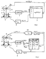
- FIG. 1 is based on a signal flow / functional block diagram the guide system according to the invention in a first embodiment variant, working according to the method according to the invention, shown.
- the instantaneous position of the rail vehicle shown schematically at 3 on rails 5 is determined by means of a position detector 1.
- a signal A 1 (POS) identifying the actual position of the vehicle 3 appears on the detector 1 or the position detection device 1 .
- the positions traveled by the vehicle 3, for example on a certain route from one place to another, as represented by a, b,..., are stored as an output address part, and the different speeds v 1 , v 2 , ..., v n , which the vehicle can drive on the given route, also here as an address part.
- the position address parts and speed address parts are, as shown, stored directly associated with inclination control signals ⁇ S , thus inclination control signals as a function of the positions and the possible speeds ⁇ S (POS, V).
- the instantaneous or actual speed of the vehicle 3 is recorded using a speed detection device 9; On the output side, a signal A 9 (v) identifying the instantaneous speed v IST of the vehicle 3 appears, which is likewise fed to the storage device 7.
- the output signals of the position detection unit 1 and the speed detection unit 9 act on addressing inputs ADR on the memory unit 7, on which now, clocked, on the output side, as shown at the output A 7 , depending on the instantaneous position and the instantaneous speed of the vehicle 3, assigned tilt adjustment signals ⁇ s ( POS, v) are issued.
- bank tilt control signals ⁇ S are fed to a bank tilt actuator arrangement 11 on the vehicle 3 or on another vehicle of a rail vehicle train, namely a control input E 11 , which actuating device controls the bank tilt ⁇ of a load, such as people to be transported, on the vehicle 3 adjusted according to the respective requirements. If the actual position is set on one vehicle and the bank on another of a train, the known actual position difference is of course taken into account.
- the required bank angle ⁇ of the load-bearing floor 13 can be determined in advance for each such position a, b, ... and is a control signal ⁇ s stored in the memory device 7.
- the invention is therefore based on the knowledge that a track line model yes exists or can be recorded, either given by the real route itself or its recorded one and stored characteristic data.
- the vehicle under consideration must be used for the bank position just be locked in the correct position on the model and its instantaneous speed are taken into account.
- position detector 1 can, as an example of a non-vehicle-based position detection system, for example, the well-known satellite-based GPS system. With such a variant can the vehicle-external position detection device for the vehicle 3 at the same time, by time derivative of the position signal, the speed detection device 9 form.
- the position detection device can also be wired, through a position monitoring system external to the vehicle for the vehicle 3 or can be formed by a detector be realized on the vehicle, which in corresponding Markings provided along the track registered, such as counts.
- a wired system e.g. a well-known line train ladder system be used.
- the position detection device can also be supported by the vehicle 1 formed, for example, by a wheel revolution counter and thus register a distance traveled, which by relating to external markings of the mentioned Type or with supplied reference signals at predetermined Positions along the track with the physical ACTUAL position is synchronized so that the measured Driving distance indicates the actual position of the vehicle.
- the speed signal in this case ACTUAL position signal is formed by deriving it over time will.
- FIG. 1 A reduced memory expenditure with a view of FIG. 1 results in a preferred embodiment of the inventive Management system, which according to the invention Method works and is shown in Fig. 2.
- the output signal A 1 (POS) of the position detection unit 1 acts on the addressing input E ADR of a memory device 27, in which, at predetermined positions along the track 5, corresponding to a, b, ..., track characteristics are stored, in particular, correct sign, radii of curvature r of Curves and, likewise with the correct sign, there predominant track elevations ⁇ G.
- the current track characteristics called up by the output signal of the position detection unit 1 are fed out of the memory device 27, corresponding to the signal A 27 (r, ⁇ G ), to a computing device 29, as is the output signal A 9 (v) of the speed detection device corresponding to the instantaneous speed of the vehicle 3 9.
- bank setting signals ⁇ S (POS, v) are fed to the control input E 11 of the bank setting device 11 on the vehicle 3 in the computing device 29, based on the currently prevailing track characteristics and the current vehicle speed.
- the necessary control signals can be calculated "foresighted” taking into account positions that have not yet been reached or the track characteristics prevailing there, if one takes into account that the instantaneous speed of the vehicle at sufficiently close distances between positions a, b etc. can be used as constant or calculated by acceleration or deceleration extrapolation.
- a constant or, for example, depending on the curve conditions, a variable offset ⁇ POS is superimposed on the instantaneous position signal.
- the cross slope on a multi-car train of a given length in the front car according to its registered Actual position are placed on the following wagons, based on the recorded actual position on the front carriage and taking into account the longitudinal distances, from the front Carriage to the next one considered.
- you can also from the recorded actual position of the rearmost or one any wagon in between can be assumed and in the carriage composition forwards or backwards, the respective Taking into account distances, the inclination of the wagon load floor be put.
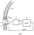
- Vehicle 3 shown schematically here in supervision bears a front with respect to its direction of travel f optoelectronic converter 31. He takes it while driving Image of the train 5 lying in front of him, which at the same time as an inherent track characteristic memory 27 is used. That with the optoelectronic converter 31 determined image is processed on an image evaluation unit 33, especially the sequence of the track pictures discriminated against and from it track characteristics GC, like those mentioned Radii and track elevation issued. The current speed will either, as already described was bound to the vehicle or from outside the vehicle detected or, as shown in Fig. 3, based on the Image sequence of the optoelectronic converter 31 determined.
- the optoelectronic converter 31 thus forms at the same time position detector 1 and instantaneous speed detector 9, like the reference numerals in parentheses hint.
- the actuating signal ⁇ S (GC, v) corresponding to the signal pair GC / v is output to a memory device 37 and in turn fed to the control input E 11 of the bank-setting actuator 11.
- the control signal is also determined on a computing unit instead of the memory device 37 from the track characteristics and the instantaneous speed.
- the characteristic track data are preferably in the sense of a "teach-in" determined that not necessarily these sizes itself, but directly dependent on it, like lateral acceleration and their direction during a teach-in drive of the vehicle 3 with known measuring devices, such as gyroscopes, pendulums, Inclination sensors etc., recorded and e.g. in memory 27 2 are stored.
- the respective teach-in driving speed used as a standardization variable the data determined in this way together with one each the teach-in speed standardized ACTUAL speed from the speed detection device 9, as shown in FIG. 2, utilize.
- the guide system according to the invention is implemented, to connect at least a second guide system in parallel to the guide system according to the invention, in order firstly to be able to carry out a redundancy check of the actuating signals supplied by both systems for the bank-tilt actuating device, and in the event of deviations in the actuating signals ⁇ S , that exceed a specified level, to take adequate precautions on the vehicle, for example to tie the bank of the bank to the second guidance system, if the latter is more fail-safe, for example.
- a redundant guidance system for example a measurement guidance system known per se, makes the bank control less efficient in accordance with the current requirements does not bother because this case only occurs as a makeshift operation.
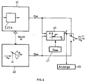
- the guide system is shown schematically in block 41 up to the output of the transverse inclination control signal ⁇ S , here referred to as ⁇ SE .
- the guide system 41 according to the invention comprises a memory of the types 7, 27, 5 illustrated with reference to FIGS. 1 to 3.
- Another guidance system is shown schematically with block 43 and is preferably based on the metrological detection of a variable related to the transverse acceleration a q , as shown schematically with the gyro in block 43.
- This guidance system also supplies a control signal ⁇ Sm in its own way. Both control signals ⁇ S or other signals that clearly determine them are compared with one another on a comparison unit 45 as to whether they do not differ from one another by more than a maximum dimension ⁇ max that can be predetermined at a specification unit 47.
- the vehicle 3 can be guided, for example, with the safer of the two guidance systems 41, 43, even if the more secure system in terms of input is less in terms of control technology is precise.
- the system 43 measures the lateral acceleration conditions on the vehicle in terms of measurement technology, such a system 43 is used in this case, even if it is far less precise in terms of control technology, as a "makeshift system" for controlling or guiding the bank on the vehicle 3.
- the comparison unit 45 switches the input E 11 of the bank adjustment actuator 11 according to FIGS. 1 to 3 to the auxiliary system 43 based on the lateral acceleration measurement, for example already known. At the same time, as shown in FIG. 4 at 49, this situation is displayed, for example.
- the lateral acceleration or the one defining it Size measuring system 43 must inevitably on the vehicle Sensors for lateral acceleration detection may be provided, which in a teach-in phase for the system according to the invention 41 can be used by, as previously described was driven a distance with the vehicle and the metrologically recorded track characteristics be loaded into a storage device.
- each vehicle 1 to 5 shows a train composition, for example with railcars 1 and 5, constellated for travel in the direction v. If required, each vehicle 1 to 5 has an actuator unit 11 for the load floor transverse position, as has been described.
- a guide system 43 S according to the invention and a system 41 S based on lateral acceleration measurement, as has already been explained with reference to FIG. 4, are provided on the railcar 5, completely symmetrically.
- the systems on railcar 1 act as a master system (M), those on car 5 as a slave system (S).
- the master system 43 M supplies the actuating signals ⁇ for all carriages 1 to 5 equipped with bank control of the type described.
- the overall master system on the carriage 1 monitors itself, for example by the current manipulated variable for the load floor on one of the carriages, output by the system 43 according to the invention M , is compared with that of the system 41 M. If these control signals deviate from one another in such a way that this is no longer plausible, the control of the load floor cross inclinations of all carriages 1 to 5 is transferred to the slave system 43 S according to the invention, as is shown schematically in FIG. 5 by the switchover unit 60.
- Plausibility is also monitored on the overall slave system in the rearmost carriage 5, for example by comparing the actuating signals of the system 43 S according to the invention and the 41 S based on measurement. If a no longer plausible deviation of these control signals is detected, it is again concluded that the system 43 S according to the invention is faulty, whereupon the system 41 M based on the measurement temporarily takes over the bank control. If this system is also defective, which can be detected, for example, by comparing the chassis twist and the bank setting signal, or if one or more of the bank setting members 11 is defective, the system is switched to emergency operation and the train is operated at control speed.
Landscapes
- Engineering & Computer Science (AREA)
- Mechanical Engineering (AREA)
- Control Of Position, Course, Altitude, Or Attitude Of Moving Bodies (AREA)
- Vehicle Body Suspensions (AREA)
- Train Traffic Observation, Control, And Security (AREA)
- Lighting Device Outwards From Vehicle And Optical Signal (AREA)
- Body Structure For Vehicles (AREA)
- Guiding Agricultural Machines (AREA)
- Forklifts And Lifting Vehicles (AREA)
- Conveying And Assembling Of Building Elements In Situ (AREA)
- Machines For Laying And Maintaining Railways (AREA)
Claims (13)
- Système de guidage comprenant :au moins un véhicule ferroviaire (3) pourvu d'un plancher de charge (13) monté pivotant dans le sens latéral, et d'un dispositif de réglage (11) pour le réglage du plancher (13) suivant un angle d'inclinaison latérale qui est réglé par l'intermédiaire d'au moins un signal de réglage d'inclinaison latérale (αS, αSE, αSm),une commande d'actionneur qui, en fonction de l'accélération agissant sur une charge, agit sur le dispositif de réglage (11) de manière à réduire l'angle entre la perpendiculaire au plancher de charge et le sens d'accélération,un dispositif de détection de position (1) pour détecter la position réelle du véhicule ferroviaire (POS),une unité de détermination de vitesse réelle (9) pour déterminer la vitesse réelle du véhicule ferroviaire (VIST),une unité de mémoire (7) pour générer un premier signal de réglage d'inclinaison latérale (αS, αSE,),
caractériséen ce qu'il est prévu sur le véhicule ferroviaire (3), comme système provisoire (43), au moins un dispositif de détection d'accélération latérale à l'aide d'une technique de mesure, pour déterminer un second signal de réglage d'inclinaison latérale (αSm), eten ce qu'il est prévu un dispositif de comparaison (45),
étant précisé que la sortie du dispositif de détection de position (1) et la sortie du dispositif de détermination de vitesse (9) agissent chacune sur une entrée de sélection de sortie du dispositif de mémoire (7) pour générer le premier signal de réglage d'inclinaison latérale (αS, αSE,), et étant précisé que la sortie du dispositif de mémoire (7) et la sortie du système provisoire (43) agissent sur le dispositif comparateur (45), dont la sortie agit sur le dispositif de réglage (11), moyennant quoi, en fonctionnement, le dispositif comparateur (45) relie activement soit la sortie du dispositif de mémoire (7), soit la sortie du système provisoire (43) au dispositif de réglage (11). - Système de guidage comprenantau moins un véhicule ferroviaire (3) pourvu d'un plancher de charge (13) monté pivotant dans le sens latéral, et d'un dispositif de réglage (11) pour le réglage du plancher (13) suivant un angle d'inclinaison latérale qui est réglé par l'intermédiaire d'au moins un signal de réglage d'inclinaison latérale (αS, αSE, αSm),une commande d'actionneur qui, en fonction de l'accélération agissant sur une charge, agit sur le dispositif de réglage (11) de manière à réduire l'angle entre la perpendiculaire au plancher de charge et le sens d'accélération,un dispositif de détection de position (1) pour détecter la position réelle du véhicule ferroviaire (POS),une unité de détermination de vitesse réelle (9) pour déterminer la vitesse réelle du véhicule ferroviaire (VIST),une unité de mémoire (27),une unité de calcul (29) pour générer un premier signal de réglage d'inclinaison latérale (αS, αSE),
caractériséen ce qu'il est prévu sur le véhicule ferroviaire (3), comme système provisoire (43), au moins un dispositif de détection d'accélération latérale à l'aide d'une technique de mesure, pour déterminer un second signal de réglage d'inclinaison latérale (αSm), eten ce qu'il est prévu un dispositif de comparaison (45),
étant précisé que la sortie du dispositif de détection de position (1, 31) agit sur une entrée de sélection de sortie du dispositif de mémoire (27), dont la sortie agit avec celle du dispositif de détermination de vitesse (9) sur l'unité de calcul (29) pour générer le premier signal de réglage d'inclinaison latérale (αS, αSE), et étant précisé que la sortie de l'unité de calcul (29) et la sortie du système provisoire (43) agissent sur le dispositif comparateur (45), dont la sortie agit sur le dispositif de réglage (11), moyennant quoi, en fonctionnement, le dispositif comparateur (45) rélie activement soit la sortie du dispositif de mémoire (7), soit la sortie du système provisoire (43) au dispositif de réglage (11). - Système selon la revendication 1 ou 2, caractérisé en ce que le dispositif comparateur (45) transmet activement l'un des signaux de réglage d'inclinaison latérale (αS, αSE, αSm) au dispositif de réglage (11).
- Système selon l'une des revendications précédentes, caractérisé en ce que le dispositif de détection de position (1) comprend un dispositif de synchronisation pour synchroniser la position de véhicule ferroviaire détectée (POS) avec la position réelle physique du véhicule ferroviaire.
- Système selon l'une des revendications 1 à 4, caractérisé en ce qu'il est prévu, montés sur le véhicule ferroviaire (3) :le dispositif de détection de position (1) et/oule dispositif de détermination de vitesse (9) et/oule dispositif de mémoire (7, 27),
et en ce que des liaisons sont établies, sans fil et/ou par l'intermédiaire d'un dispositif formant ligne de données, entre les dispositifs portés par le véhicule et les dispositifs non portés par le véhicule. - Système selon l'une des revendications 1 à 5, caractérisé en ce qu'on prévoit sur une voiture de véhicule ferroviaire (1,..., 5) au moins le dispositif de détection de position, tandis que le dispositif de réglage (11) est prévu sur au moins une autre voiture de véhicule ferroviaire (1,...,5) accouplée à la première, voiture de véhicule ferroviaire (1,..., 5) désignant d'une manière générale une partie d'un ensemble de véhicules ferroviaires.
- Système selon l'une des revendications 1 à 6, caractérisé en ce que dans un ensemble de véhicules, deux des voitures (1,...,5) sont, conçues comme les véhicules ferroviaires dans le sens des revendications citées, et en ce que suivant le sens de marche (v), un véhicule ferroviaire agit comme véhicule pilote et l'autre comme véhicule asservi, étant précisé que la commande d'inclinaison latérale, au moins en cas de panne du dispositif de détection de position (1) du véhicule pilote, devient fonction du dispositif de détection de position (1) du véhicule asservi.
- Véhicule ferroviaire comportant deux systèmes de guidage selon l'une des revendications 1 à 7 fonctionnant indépendamment l'un de l'autre comme système pilote et système asservi.
- Procédé pour commander l'inclinaison latérale du plancher porteur de charge (13) d'un véhicule ferroviaire (3) dont l'inclinaison latérale est réglable, en mouvement, ce procédé consistantà définir, à partir du tracé de la voie (5) connu préalablement, de la position réelle du véhicule ferroviaire (POS) et de sa vitesse réelle (vIST), un premier signal de réglage d'inclinaison latérale (αS, αSE) pour le réglage du plancher porteur de charge (13),
caractériséen ce que, à l'aide d'un dispositif de détection d'accélération latérale comme système provisoire (43), un second signal de réglage d'inclinaison latérale (αSm) est défini,en ce que le premier signal de réglage d'inclinaison latérale (αS, αSE) est comparé au second (αSm) eten ce que, en fonction du résultat de la comparaison, soit le premier (αS, αSE), soit le second signal de réglage d'inclinaison latérale (αSm) est utilisé pour le réglage de l'inclinaison latérale du plancher de charge. - Procédé selon la revendication 9, caractérisé en ce que le choix du premier (αS, αSE) ou du second signal de réglage d'inclinaison latérale (αSm) se fait à partir d'une grandeur maximale Δmax apte à être prédéfinie comme écart entre les signaux de réglage d'inclinaison latérale (αS, αSE, αSm).
- Procédé selon la revendication 9 ou 10, caractérisé en ce qu'on mesure des données de la voie (5) significatives pour l'inclinaison latérale, grâce à un parcours de reconnaissance, on les met en mémoire et on les utilise par la suite pour définir et régler l'inclinaison latérale.
- Procédé selon l'une des revendications 9 à 11, caractérisé en ce qu'on met en oeuvre le procédé deux fois, indépendamment, sur un train de véhicules ferroviaires, on procède à la commande d'inclinaison latérale selon un premier procédé, on vérifie la plausibilité du signal de réglage d'inclinaison latérale et, si ledit signal n'est pas plausible, on confie la commande d'inclinaison latérale au second procédé.
- Véhicule ferroviaire pourvu d'un système de guidage selon l'une des revendications 1 à 7 ou d'une commende d'inclinaison latérale de plancher de charge fonctionnent selon le procédé des revendications 9 à 12.
Priority Applications (10)
| Application Number | Priority Date | Filing Date | Title |
|---|---|---|---|
| AT94119183T ATE171121T1 (de) | 1994-12-05 | 1994-12-05 | Führungssystem und verfahren zur steuerung der querneigung an einem schienenfahrzeug |
| EP94119183A EP0647553B1 (fr) | 1994-12-05 | 1994-12-05 | Système de guidage et méthode pour la commande de la pente latérale d'un véhicule ferroviaire |
| DE59406923T DE59406923D1 (de) | 1994-12-05 | 1994-12-05 | Führungssystem und Verfahren zur Steuerung der Querneigung an einem Schienenfahrzeug |
| FI963023A FI963023A7 (fi) | 1994-12-05 | 1995-12-05 | Ohjausjärjestelmä ja menetelmä poikittaiskallistuksen ohjaamiseksi kis koajoneuvossa |
| US08/687,410 US5775230A (en) | 1994-12-05 | 1995-12-05 | Guidance system and process for controlling the lateral inclination on a rail vehicle |
| PCT/CH1995/000289 WO1996017761A1 (fr) | 1994-12-05 | 1995-12-05 | Systeme de guidage et procede de regulation de l'inclinaison laterale d'un vehicule sur rails |
| AU39217/95A AU698963B2 (en) | 1994-12-05 | 1995-12-05 | Guiding system and process for controlling the lateral inclination of a rail vehicle |
| JP8517221A JPH09508873A (ja) | 1994-12-05 | 1995-12-05 | 軌道車両における横方向傾斜状態の制御のための案内誘導装置システム及び方法 |
| CA002182481A CA2182481A1 (fr) | 1994-12-05 | 1995-12-05 | Systeme de guidage et procede de regulation de l'inclinaison laterale d'un vehicule sur rails |
| NO963271A NO963271D0 (no) | 1994-12-05 | 1996-08-05 | Föringssystem og fremgangsmåte for styring av sideveis krengning ved et skinnegående kjöretöy |
Applications Claiming Priority (1)
| Application Number | Priority Date | Filing Date | Title |
|---|---|---|---|
| EP94119183A EP0647553B1 (fr) | 1994-12-05 | 1994-12-05 | Système de guidage et méthode pour la commande de la pente latérale d'un véhicule ferroviaire |
Publications (3)
| Publication Number | Publication Date |
|---|---|
| EP0647553A2 EP0647553A2 (fr) | 1995-04-12 |
| EP0647553A3 EP0647553A3 (fr) | 1995-06-28 |
| EP0647553B1 true EP0647553B1 (fr) | 1998-09-16 |
Family
ID=8216504
Family Applications (1)
| Application Number | Title | Priority Date | Filing Date |
|---|---|---|---|
| EP94119183A Expired - Lifetime EP0647553B1 (fr) | 1994-12-05 | 1994-12-05 | Système de guidage et méthode pour la commande de la pente latérale d'un véhicule ferroviaire |
Country Status (10)
| Country | Link |
|---|---|
| US (1) | US5775230A (fr) |
| EP (1) | EP0647553B1 (fr) |
| JP (1) | JPH09508873A (fr) |
| AT (1) | ATE171121T1 (fr) |
| AU (1) | AU698963B2 (fr) |
| CA (1) | CA2182481A1 (fr) |
| DE (1) | DE59406923D1 (fr) |
| FI (1) | FI963023A7 (fr) |
| NO (1) | NO963271D0 (fr) |
| WO (1) | WO1996017761A1 (fr) |
Families Citing this family (13)
| Publication number | Priority date | Publication date | Assignee | Title |
|---|---|---|---|---|
| SE509153C2 (sv) * | 1995-11-07 | 1998-12-07 | Const Y Aux Ferrocarriles Sa | Lutningssystem för järnvägsvagnar |
| AT500703B1 (de) * | 1995-11-10 | 2007-03-15 | Construcciones Y Aux De Ferroc | Neigevorrichtung für ein schienenfahrzeug |
| DE19703322C1 (de) * | 1997-01-30 | 1998-03-26 | Abb Daimler Benz Transp | Neigungssteuerung für Schienenfahrzeuge |
| DE19910255A1 (de) * | 1999-03-08 | 2000-09-14 | Abb Daimler Benz Transp | Neigesteuerung für ein Schienenfahrzeug |
| FR2794707B1 (fr) * | 1999-06-11 | 2003-03-14 | Alstom | Procede et dispositif de commande de l'inclinaison d'un vehicule ferroviaire pendulaire |
| AU1145001A (en) * | 1999-10-27 | 2001-05-08 | Deutsche Bahn Ag | Rail mounted vehicle segment with a centrifugal force compensation device integrated into the body thereof |
| RU2160678C1 (ru) * | 2000-06-26 | 2000-12-20 | ООО "Селтон-М" | Способ функционирования монорельсовой транспортной системы навесного типа и монорельсовая транспортная система навесного типа |
| US8560217B2 (en) * | 2007-06-15 | 2013-10-15 | Cadec Global, Inc. | System and method for predicting vehicle rollover using position tracking |
| FR2949860B1 (fr) | 2009-09-04 | 2012-04-20 | Soc Nat Des Chemins De Fer Francais Sncf | Procede de qualification d'un vehicule ferroviaire. |
| JP5959378B2 (ja) | 2012-09-11 | 2016-08-02 | 川崎重工業株式会社 | 荷重測定方法及び装置、荷重測定装置を備えた鉄道車両、並びに荷重管理システム |
| JP6495663B2 (ja) * | 2015-01-13 | 2019-04-03 | 株式会社東芝 | 列車制御装置、列車制御方法及びプログラム |
| JP6756380B2 (ja) * | 2016-12-27 | 2020-09-16 | 日本電気株式会社 | 第1の列車搭載装置、第2の列車搭載装置、列車衝突防止システム、方法およびプログラム |
| CN111823214A (zh) * | 2020-07-22 | 2020-10-27 | 中信重工开诚智能装备有限公司 | 一种自动调整夹紧力的轨道巡检机器人驱动装置 |
Family Cites Families (12)
| Publication number | Priority date | Publication date | Assignee | Title |
|---|---|---|---|---|
| US3717104A (en) * | 1970-07-08 | 1973-02-20 | United Aircraft Corp | Active roll controling truck stabilizing mechanism |
| ES398517A1 (es) * | 1971-01-28 | 1974-08-16 | Fiat Spa | Perfeccionamientos en un dispositivo electronico integra- dor. |
| DE2252526A1 (de) * | 1972-10-26 | 1974-05-02 | Continental Gummi Werke Ag | Neigungssteuerung fuer fahrzeugaufbauten |
| US3884437A (en) * | 1973-10-09 | 1975-05-20 | Westinghouse Air Brake Co | Train control system for transit vehicles |
| US3902691A (en) * | 1973-11-27 | 1975-09-02 | Owen J Ott | Automatic vehicle suspension system |
| SE509153C2 (sv) * | 1995-11-07 | 1998-12-07 | Const Y Aux Ferrocarriles Sa | Lutningssystem för järnvägsvagnar |
| FR2574036A1 (fr) * | 1984-12-03 | 1986-06-06 | Anf Ind | Procede et systeme d'amortissement des mouvements parasites des vehicules ferroviaires |
| EP0271592B1 (fr) * | 1986-12-15 | 1989-05-24 | Honeywell Regelsysteme GmbH | Procédé et dispositif de réglage de l'inclinaison |
| FR2633887B1 (fr) * | 1988-07-06 | 1996-05-03 | Durand Charles | Procede et dispositif pour le controle de la suspension active de caisse sur un vehicule ferroviaire |
| SE465667B (sv) * | 1989-07-13 | 1991-10-14 | Asea Brown Boveri | Anordning foer styrning av korglutning i kurvor foer spaarbundet fordon |
| US5429329A (en) * | 1994-01-31 | 1995-07-04 | Wallace; Charles C. | Robotic railroad accident prevention vehicle and associated system elements |
| IT1280854B1 (it) * | 1995-04-07 | 1998-02-11 | Fiat Ferroviaria Spa | "veicolo ferroviario con cassa ad assetto variabile" |
-
1994
- 1994-12-05 AT AT94119183T patent/ATE171121T1/de not_active IP Right Cessation
- 1994-12-05 DE DE59406923T patent/DE59406923D1/de not_active Expired - Fee Related
- 1994-12-05 EP EP94119183A patent/EP0647553B1/fr not_active Expired - Lifetime
-
1995
- 1995-12-05 WO PCT/CH1995/000289 patent/WO1996017761A1/fr not_active Ceased
- 1995-12-05 FI FI963023A patent/FI963023A7/fi unknown
- 1995-12-05 JP JP8517221A patent/JPH09508873A/ja active Pending
- 1995-12-05 AU AU39217/95A patent/AU698963B2/en not_active Ceased
- 1995-12-05 US US08/687,410 patent/US5775230A/en not_active Expired - Fee Related
- 1995-12-05 CA CA002182481A patent/CA2182481A1/fr not_active Abandoned
-
1996
- 1996-08-05 NO NO963271A patent/NO963271D0/no not_active Application Discontinuation
Also Published As
| Publication number | Publication date |
|---|---|
| US5775230A (en) | 1998-07-07 |
| NO963271L (no) | 1996-08-05 |
| FI963023L (fi) | 1996-07-31 |
| EP0647553A3 (fr) | 1995-06-28 |
| CA2182481A1 (fr) | 1996-06-13 |
| ATE171121T1 (de) | 1998-10-15 |
| WO1996017761A1 (fr) | 1996-06-13 |
| NO963271D0 (no) | 1996-08-05 |
| JPH09508873A (ja) | 1997-09-09 |
| DE59406923D1 (de) | 1998-10-22 |
| EP0647553A2 (fr) | 1995-04-12 |
| AU698963B2 (en) | 1998-11-12 |
| AU3921795A (en) | 1996-06-26 |
| FI963023A0 (fi) | 1996-07-31 |
| FI963023A7 (fi) | 1996-07-31 |
Similar Documents
| Publication | Publication Date | Title |
|---|---|---|
| DE69529474T2 (de) | Spurdatenspeicherung in einem positionsgeregelten neigbaren system | |
| DE4228414B4 (de) | Verfahren und Vorrichtung zur Aufbereitung von Sensorsignalen | |
| EP3331734B1 (fr) | Système de frein pour un véhicule ferroviaire | |
| DE69828316T2 (de) | Verfahren und vorrichtung zum feststellen des entgleisens von eisenbahnwagen | |
| DE69510871T2 (de) | Steuerverfahren zur Lenkung von Laufwerken mit einstellbaren Rädern einer auf Schienen fahrenden Einheit und dieses Verfahren nutzende Einheit | |
| EP2812225B1 (fr) | Procédé pour la production de recommandations d'action pour le conducteur d'un véhicule ferroviaire ou pour des signaux de commande pour le véhicule ferroviaire, au moyen d'un système d'assistance à la conduite, et système d'assistance à la conduite | |
| EP3676138B1 (fr) | Procédé et dispositif de détermination de valeurs réelles réeles liées au freinage d'un véhicule ferroviaire pour effectuer un freinage à décélération régulée avec capteurs centralisés | |
| DE112009000648T5 (de) | System und Verfahren zum Verifizieren einer Einrichtung eines Zuges mit verteilter Antriebskraft | |
| EP3583012A1 (fr) | Véhicule d'auscultation de voie et procédé de détection d'une assiette de voie | |
| EP0647553A2 (fr) | Système de guidage et méthode pour la commande de la pente latérale d'un véhicule ferroviaire | |
| DE102005051077A1 (de) | Verfahren zum Erfassen und Berücksichtigen von Seitenwindbelastungen bei einem in Fahrt befindlichen Schienenfahrzeug und dessen entsprechend ausgeführter Endwagen | |
| DE69306139T2 (de) | System zur Beherrschung der Drehung eines Eisenbahnwagenkastens um die Längsachse | |
| CH674180A5 (fr) | ||
| EP0271592B1 (fr) | Procédé et dispositif de réglage de l'inclinaison | |
| DE212021000415U1 (de) | On-Board-Gleisprüfsystem | |
| EP0568167B1 (fr) | Procédé pour la détermination de la résistance au roulement de véhicules ferroviaires | |
| EP3310637A1 (fr) | Dispositif de contrôle et procédé de contrôle d'un profil défini d'un convoi composé de véhicules, notamment de véhicules ferroviaires | |
| EP0770233B1 (fr) | Procede et dispositif de regulation de l'inclinaison par rapport a la terre de la caisse de wagon de vehicules sur rails | |
| DE69802247T2 (de) | Transporteinrichtung mit optischer und mechanischer führung | |
| EP0860340B1 (fr) | Méthode et dispositif pour générer un signal de capteur | |
| EP3990322B1 (fr) | Procédé d'étalonnage de l'orientation d'un capteur d'accélération disposé dans un véhicule | |
| DE102006062559A1 (de) | Verfahren zum Messen einer maximalen Zuglänge | |
| EP0719688B1 (fr) | Système de guidage pour vehicules ferroviaires | |
| DE3827363C2 (fr) | ||
| DE3821281C2 (de) | Einrichtung zur Messung der Neigung von Fahrzeugen in Richtung der Bahnbewegung |
Legal Events
| Date | Code | Title | Description |
|---|---|---|---|
| PUAI | Public reference made under article 153(3) epc to a published international application that has entered the european phase |
Free format text: ORIGINAL CODE: 0009012 |
|
| AK | Designated contracting states |
Kind code of ref document: A2 Designated state(s): AT BE CH DE DK ES FR GB GR IE IT LI NL PT SE |
|
| PUAL | Search report despatched |
Free format text: ORIGINAL CODE: 0009013 |
|
| AK | Designated contracting states |
Kind code of ref document: A3 Designated state(s): AT BE CH DE DK ES FR GB GR IE IT LI LU MC NL PT SE |
|
| 17P | Request for examination filed |
Effective date: 19950731 |
|
| RBV | Designated contracting states (corrected) |
Designated state(s): AT BE CH DE DK ES FR GB GR IE IT LI NL PT SE |
|
| 17Q | First examination report despatched |
Effective date: 19960315 |
|
| RAP1 | Party data changed (applicant data changed or rights of an application transferred) |
Owner name: FIAT-SIG SCHIENENFAHRZEUGE AG |
|
| GRAG | Despatch of communication of intention to grant |
Free format text: ORIGINAL CODE: EPIDOS AGRA |
|
| GRAG | Despatch of communication of intention to grant |
Free format text: ORIGINAL CODE: EPIDOS AGRA |
|
| GRAH | Despatch of communication of intention to grant a patent |
Free format text: ORIGINAL CODE: EPIDOS IGRA |
|
| GRAH | Despatch of communication of intention to grant a patent |
Free format text: ORIGINAL CODE: EPIDOS IGRA |
|
| GRAA | (expected) grant |
Free format text: ORIGINAL CODE: 0009210 |
|
| AK | Designated contracting states |
Kind code of ref document: B1 Designated state(s): AT BE CH DE DK ES FR GB GR IE IT LI NL PT SE |
|
| PG25 | Lapsed in a contracting state [announced via postgrant information from national office to epo] |
Ref country code: NL Free format text: LAPSE BECAUSE OF FAILURE TO SUBMIT A TRANSLATION OF THE DESCRIPTION OR TO PAY THE FEE WITHIN THE PRESCRIBED TIME-LIMIT Effective date: 19980916 Ref country code: IT Free format text: LAPSE BECAUSE OF FAILURE TO SUBMIT A TRANSLATION OF THE DESCRIPTION OR TO PAY THE FEE WITHIN THE PRE;WARNING: LAPSES OF ITALIAN PATENTS WITH EFFECTIVE DATE BEFORE 2007 MAY HAVE OCCURRED AT ANY TIME BEFORE 2007. THE CORRECT EFFECTIVE DATE MAY BE DIFFERENT FROM THE ONE RECORDED.SCRIBED TIME-LIMIT Effective date: 19980916 Ref country code: GR Free format text: LAPSE BECAUSE OF NON-PAYMENT OF DUE FEES Effective date: 19980916 Ref country code: FR Free format text: LAPSE BECAUSE OF FAILURE TO SUBMIT A TRANSLATION OF THE DESCRIPTION OR TO PAY THE FEE WITHIN THE PRESCRIBED TIME-LIMIT Effective date: 19980916 Ref country code: ES Free format text: THE PATENT HAS BEEN ANNULLED BY A DECISION OF A NATIONAL AUTHORITY Effective date: 19980916 |
|
| REF | Corresponds to: |
Ref document number: 171121 Country of ref document: AT Date of ref document: 19981015 Kind code of ref document: T |
|
| REG | Reference to a national code |
Ref country code: CH Ref legal event code: EP |
|
| REF | Corresponds to: |
Ref document number: 59406923 Country of ref document: DE Date of ref document: 19981022 |
|
| REG | Reference to a national code |
Ref country code: CH Ref legal event code: NV Representative=s name: TROESCH SCHEIDEGGER WERNER AG |
|
| REG | Reference to a national code |
Ref country code: IE Ref legal event code: FG4D Free format text: GERMAN |
|
| PG25 | Lapsed in a contracting state [announced via postgrant information from national office to epo] |
Ref country code: SE Free format text: LAPSE BECAUSE OF FAILURE TO SUBMIT A TRANSLATION OF THE DESCRIPTION OR TO PAY THE FEE WITHIN THE PRESCRIBED TIME-LIMIT Effective date: 19981216 Ref country code: DK Free format text: LAPSE BECAUSE OF FAILURE TO SUBMIT A TRANSLATION OF THE DESCRIPTION OR TO PAY THE FEE WITHIN THE PRESCRIBED TIME-LIMIT Effective date: 19981216 |
|
| PG25 | Lapsed in a contracting state [announced via postgrant information from national office to epo] |
Ref country code: PT Free format text: LAPSE BECAUSE OF FAILURE TO SUBMIT A TRANSLATION OF THE DESCRIPTION OR TO PAY THE FEE WITHIN THE PRESCRIBED TIME-LIMIT Effective date: 19981218 |
|
| PG25 | Lapsed in a contracting state [announced via postgrant information from national office to epo] |
Ref country code: BE Free format text: LAPSE BECAUSE OF NON-PAYMENT OF DUE FEES Effective date: 19981231 |
|
| GBT | Gb: translation of ep patent filed (gb section 77(6)(a)/1977) |
Effective date: 19981215 |
|
| EN | Fr: translation not filed | ||
| NLV1 | Nl: lapsed or annulled due to failure to fulfill the requirements of art. 29p and 29m of the patents act | ||
| PG25 | Lapsed in a contracting state [announced via postgrant information from national office to epo] |
Ref country code: IE Free format text: LAPSE BECAUSE OF NON-PAYMENT OF DUE FEES Effective date: 19990504 |
|
| BERE | Be: lapsed |
Owner name: FIAT-SIG SCHIENENFAHRZEUGE A.G. Effective date: 19981231 |
|
| REG | Reference to a national code |
Ref country code: IE Ref legal event code: FD4D |
|
| PLBE | No opposition filed within time limit |
Free format text: ORIGINAL CODE: 0009261 |
|
| STAA | Information on the status of an ep patent application or granted ep patent |
Free format text: STATUS: NO OPPOSITION FILED WITHIN TIME LIMIT |
|
| 26N | No opposition filed | ||
| PGFP | Annual fee paid to national office [announced via postgrant information from national office to epo] |
Ref country code: GB Payment date: 19991201 Year of fee payment: 6 |
|
| PGFP | Annual fee paid to national office [announced via postgrant information from national office to epo] |
Ref country code: AT Payment date: 19991227 Year of fee payment: 6 |
|
| PGFP | Annual fee paid to national office [announced via postgrant information from national office to epo] |
Ref country code: DE Payment date: 19991229 Year of fee payment: 6 |
|
| PG25 | Lapsed in a contracting state [announced via postgrant information from national office to epo] |
Ref country code: GB Free format text: LAPSE BECAUSE OF NON-PAYMENT OF DUE FEES Effective date: 20001205 Ref country code: AT Free format text: LAPSE BECAUSE OF NON-PAYMENT OF DUE FEES Effective date: 20001205 |
|
| GBPC | Gb: european patent ceased through non-payment of renewal fee |
Effective date: 20001205 |
|
| PG25 | Lapsed in a contracting state [announced via postgrant information from national office to epo] |
Ref country code: DE Free format text: LAPSE BECAUSE OF NON-PAYMENT OF DUE FEES Effective date: 20011002 |
|
| PGFP | Annual fee paid to national office [announced via postgrant information from national office to epo] |
Ref country code: CH Payment date: 20040226 Year of fee payment: 10 |
|
| PG25 | Lapsed in a contracting state [announced via postgrant information from national office to epo] |
Ref country code: LI Free format text: LAPSE BECAUSE OF NON-PAYMENT OF DUE FEES Effective date: 20041231 Ref country code: CH Free format text: LAPSE BECAUSE OF NON-PAYMENT OF DUE FEES Effective date: 20041231 |
|
| REG | Reference to a national code |
Ref country code: CH Ref legal event code: PL |