EP0647761A1 - Système de store roulant - Google Patents
Système de store roulant Download PDFInfo
- Publication number
- EP0647761A1 EP0647761A1 EP94104835A EP94104835A EP0647761A1 EP 0647761 A1 EP0647761 A1 EP 0647761A1 EP 94104835 A EP94104835 A EP 94104835A EP 94104835 A EP94104835 A EP 94104835A EP 0647761 A1 EP0647761 A1 EP 0647761A1
- Authority
- EP
- European Patent Office
- Prior art keywords
- roller shutter
- shutter system
- parts
- connecting element
- carrier
- Prior art date
- Legal status (The legal status is an assumption and is not a legal conclusion. Google has not performed a legal analysis and makes no representation as to the accuracy of the status listed.)
- Granted
Links
- 230000007246 mechanism Effects 0.000 claims abstract description 16
- 239000002184 metal Substances 0.000 claims description 4
- 238000004804 winding Methods 0.000 description 15
- 230000006978 adaptation Effects 0.000 description 3
- 230000002349 favourable effect Effects 0.000 description 2
- 238000004519 manufacturing process Methods 0.000 description 2
- 230000003287 optical effect Effects 0.000 description 1
- 239000002990 reinforced plastic Substances 0.000 description 1
Images



Classifications
-
- E—FIXED CONSTRUCTIONS
- E06—DOORS, WINDOWS, SHUTTERS, OR ROLLER BLINDS IN GENERAL; LADDERS
- E06B—FIXED OR MOVABLE CLOSURES FOR OPENINGS IN BUILDINGS, VEHICLES, FENCES OR LIKE ENCLOSURES IN GENERAL, e.g. DOORS, WINDOWS, BLINDS, GATES
- E06B9/00—Screening or protective devices for wall or similar openings, with or without operating or securing mechanisms; Closures of similar construction
- E06B9/02—Shutters, movable grilles, or other safety closing devices, e.g. against burglary
- E06B9/08—Roll-type closures
- E06B9/11—Roller shutters
- E06B9/17—Parts or details of roller shutters, e.g. suspension devices, shutter boxes, wicket doors, ventilation openings
- E06B9/17061—Connection of the box to the guides
-
- E—FIXED CONSTRUCTIONS
- E06—DOORS, WINDOWS, SHUTTERS, OR ROLLER BLINDS IN GENERAL; LADDERS
- E06B—FIXED OR MOVABLE CLOSURES FOR OPENINGS IN BUILDINGS, VEHICLES, FENCES OR LIKE ENCLOSURES IN GENERAL, e.g. DOORS, WINDOWS, BLINDS, GATES
- E06B9/00—Screening or protective devices for wall or similar openings, with or without operating or securing mechanisms; Closures of similar construction
- E06B9/02—Shutters, movable grilles, or other safety closing devices, e.g. against burglary
- E06B9/08—Roll-type closures
- E06B9/11—Roller shutters
- E06B9/17—Parts or details of roller shutters, e.g. suspension devices, shutter boxes, wicket doors, ventilation openings
- E06B9/174—Bearings specially adapted therefor
-
- Y—GENERAL TAGGING OF NEW TECHNOLOGICAL DEVELOPMENTS; GENERAL TAGGING OF CROSS-SECTIONAL TECHNOLOGIES SPANNING OVER SEVERAL SECTIONS OF THE IPC; TECHNICAL SUBJECTS COVERED BY FORMER USPC CROSS-REFERENCE ART COLLECTIONS [XRACs] AND DIGESTS
- Y10—TECHNICAL SUBJECTS COVERED BY FORMER USPC
- Y10S—TECHNICAL SUBJECTS COVERED BY FORMER USPC CROSS-REFERENCE ART COLLECTIONS [XRACs] AND DIGESTS
- Y10S160/00—Flexible or portable closure, partition, or panel
- Y10S160/903—Roll type bracket means
Definitions
- the invention relates to a roller shutter system with lateral support parts for a winding mechanism, a bearing or the like.
- lateral guide rails for the roller shutter curtain With lateral guide rails for the roller shutter curtain, the guide rails being connected to a lateral support part.
- lateral support parts (diaphragm caps) carry the winding mechanism or a bearing for the winding shaft of a roller shutter armor.
- connecting elements projecting downwards are provided in one piece, by means of which the lateral support parts can be plugged onto lateral guide rails.
- the side guide rails are, for example, screwed to the door or window frame and serve to guide the roller shutter curtain.
- the disadvantage of such a connecting element formed in one piece with the carrier part is that the mounting element of the mounting mechanism, for example a belt or a crank, can only be led out of the roller shutter box either to the left or right of the connecting element.
- the object of the invention is therefore to provide a roller shutter system of the type mentioned, with which the relative lateral position between the support parts and the respective guide rails can be easily adapted to the respective circumstances.
- the connecting element is no longer formed in one piece with the lateral support parts, it is possible, by using different connecting elements or adjustable connecting elements, to easily adapt the relative lateral position between a respective lateral support part and the associated lateral guide rail to the respective circumstances , wherein the carrier parts and the guide rails can always be basically the same even for this adaptation.
- By adjusting the relative lateral position between the carrier part and the guide rail it is possible to adjust the position of the pulling element (for example belt or crank) emerging from the mounting mechanism attached to the carrier part in relation to the outer edge of the guide rail.
- the pulling element for example belt or crank
- connecting elements of such a set of connecting elements can be profiled, for example, in an I-shape or a Z-shape, the Z having two vertical and one horizontal web. The lateral offset between the carrier part and the guide rails can then be easily adapted over the length of the horizontal web.
- the separate connecting element in two or more parts, at least two parts being adjustable relative to one another. This makes it possible to fine-tune the setting on the spot.
- the roller shutter system according to the invention can advantageously comprise a plurality of different left and right guide rails, the connection area of which is always of the same design, so that it fits the separate connecting elements.
- this can be adapted to various conditions in the area of the guide rails, for example the type and thickness of the roller shutter curtain, the type of fastening to the door frame or to the wall, etc. the same type of separate connecting elements can be used for all guide rails.
- this problem can be solved by a two-part or multi-part guide rail, one part having an essentially identical connecting area for the separate connecting element, while the second part connected to this first part can be adapted to the respective circumstances.
- the modularity of the roller shutter system according to the invention can relate not only to different separate connecting elements and different matching guide rails, but also to several different support parts, which can optionally be attached to the guide rails, the different support parts in turn having the same connection areas or receptacles, to all of them separate connecting elements fit.
- the modularity of the roller shutter system according to the invention can relate not only to different separate connecting elements and different matching guide rails, but also to several different support parts, which can optionally be attached to the guide rails, the different support parts in turn having the same connection areas or receptacles, to all of them separate connecting elements fit.
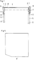
- Fig. 1 shows an embodiment of a roller shutter according to the invention (without showing the winding shaft and roller shutter curtain).
- 2, 3 and 4 each show a section from the inside according to the line AA of FIG. 2 and in a plan view an embodiment of a side support part.
- 5 shows a side cover in a side view.
- 6 and 7 schematically show exemplary embodiments for the connection of the carrier part and guide rail by means of two different separate connecting elements.
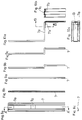
- 8a, 8b and 8c show a profiled connecting element which is straight in the longitudinal extent in a front view in a section along the line A'-A 'of FIG. 8a and in a plan view.
- 9a, 9b and 9c show exemplary embodiments of one-piece, separate connecting elements.
- 10a, 10b and 10c show an embodiment of an adjustable, separate connecting element in a side view in a section along the line BB of FIG. 10a and in a schematic plan view.
- 11 and 12 show exemplary embodiments of guide rails.
- two side support parts 1 are provided which support a bearing 2 or a winding mechanism 3.
- a winding shaft with the axis 4 can be driven via the winding mechanism 3 and a winding element (not shown in more detail), and thus a roller shutter curtain (also not shown) can be wound up.
- the roller shutter curtain is guided in lateral guide rails 5, which are fastened to a door or window frame, for example, by means of fastening screws 6.
- the carrier parts 1 are detachably connected to the guide rails 6 via separate connecting elements 7. In Fig. 1, these separate connecting elements are shown only schematically with dashed lines. A more detailed description is given in connection with FIGS. 6 to 10c. If the winding shaft is not surrounded by a roller shutter box, it may be advantageous to increase the stability if the two carrier parts 1 are connected to one another by a connecting rod 8.
- the roller shutter shown in FIG. 1 is fundamentally suitable both as a built-in roller shutter and as a finished element roller shutter, it being possible for all functionally important elements to be the same in both cases.
- the support parts 1 are installed in an already existing shaft in the lintel or door lintel and, if appropriate, are only veneered downwards.
- the entire wind-up mechanism including the carrier parts and the winding shaft is hardly visible.
- the two support parts can be arranged completely unclad in the receiving shaft.
- roller shutter is to be used as a so-called prefabricated element roller shutter, which is typically retrofitted above windows or doors from the outside, it is simply possible to attach an end cover 9 to the outside of each support part 1, without changing the other in terms of design and function important elements.
- a roller shutter box wall can be provided between the two covers 9 in order to hide the winding shaft, the bearing 2 and the winding mechanism 3 inside.
- different types of covers 9 can be attached to the outside of the respective support part 1 as required.
- the carrier parts 1 can be designed, for example, as shown in FIGS. 2 to 4.
- the carrier parts 1 shown there are formed in one piece and consist of stamped sheet metal. This makes them simple and inexpensive to manufacture.
- the carrier parts 1 have angled legs 1a at the edge. These also allow simple fastening of a wall forming the roller shutter box between two lateral support parts 1.
- the support parts 1 Left and right in FIGS. 2 and 4, the support parts 1 have profile channels 1b to increase the stability.
- the profile channel 1b on the right in FIGS. 2 and 4 also serves to receive a connecting element 7, as is shown, for example, in FIGS. 8a to 8c. This connecting element 7 serves to connect the carrier part 1 to the guide rails 5.
- connection element 7 In order to achieve a stable connection of the connecting element 7 to the carrier part 1, two tabs 10 are punched out in the carrier part 1 and bent inwards and downwards within the profiled channel 1b.
- the connecting element 7 has openings 10 at a distance from the two tabs and can thus be inserted into the tabs from below.
- the carrier part shown in FIGS. 2 to 4 has a plurality of passage openings 11 in a region 1d set back from the end faces 1c.
- the winding mechanism, the bearing or the like. can then be screwed from the outside through the through openings 11 to the carrier part 1, the screw heads not projecting beyond the end faces 1c.
- the cover plate 9 can preferably be screwed or glued to the carrier part 1, but detachable connections are also conceivable and possible.
- roller shutter system modularly with regard to the support parts, that is to say that the area of the profile channel 1b and the punched-out tabs are always of the same design in different support parts are so that they always fit the same separate connecting elements 7.
- the rest of the design of the carrier part can vary widely, for example in size to adapt to different winding diameters. But even with one and the same support part, it is possible due to the numerous pre-drilled through openings 11 without changing the support part, different types of mounting mechanisms, bearings or the like. to fix.
- FIG. 5 An embodiment of a flat cover plate 9 is shown in FIG. 5.
- FIGS. 6 and 7 show how a different relative position between the guide rail 5 and the carrier part 1 can be achieved via different separate connecting elements 7 with other identical structures. It is thus possible to adapt the lateral distance between a mounting element 12 (for example a mounting belt) and the outer edge 5a of the guide rail depending on the local conditions. 6, this distance d is approximately zero, that is to say that the mounting element 12 runs essentially along the outer edge 5a of the guide rail 5. This is possible by means of a Z-shaped profiled connecting element 7, which is inserted both in the carrier part 1 and in the guide rail 5 and is releasably connected to it.
- the detachable connector is only shown schematically in FIGS. 6 and 7. A larger distance between the mounting element 12 and the guide rail 5 can be achieved simply by using a separate Z-shaped connecting element 7, which, however, has a longer horizontal web according to FIG. 7.
- the separate connecting element is straight overall, however profiled in cross section (compare in particular Fig. 8c) to increase the stability.
- the connecting element can consist, for example, of metal or reinforced plastic.
- the connecting element 7 has two openings 7a which are suitable for being hooked into the tabs 10 of FIG. 3 from below. The connecting element 7 is then, as shown in FIG. 4, full in the channel 1b.
- FIGS. 9a to 9c Simple embodiments of I-shaped or Z-shaped connecting elements are shown in FIGS. 9a to 9c.
- FIGS. 10a to 10c show a somewhat more complex design.
- the connecting element shown there is formed in two parts, two L-shaped parts being assembled together to form a Z-shaped connecting element.
- the horizontal leg 7a of one part and the horizontal leg 7b of the other part overlap in the central region, the degree of overlap being adjustable.
- the effective length of the horizontal web of the overall Z-shaped profiled connecting element can thus be set.
- a screw can be used to fix the relative position of the legs 7a and 7b, which is screwed through both legs 7a and 7b, for example at the point indicated by a cross 13 in FIG. 10c.
- the roller shutter system according to the invention can also be used also have different types of guide rails in order to achieve optimal adaptation to the respective circumstances.
- the guide rails are then distinguished by the fact that they have a connecting region 5c which, regardless of the rest of the structure of the guide rail, is always of the same design and thus always fits the same or similar separate connecting elements (compare FIGS. 11 and 12).
- 11 shows a one-piece embodiment of a guide rail 5.
- the separate connecting element 7 can be inserted into the area 5c from above.
- the area 5d serves to guide the actual roller shutter.
- FIG. 12 shows a two-part embodiment of the guide rail.
- the first part 5a has the connecting area 5c for the connecting element 7, while the second part 5b attached to it has the guide 5b for the actual roller shutter curtain.
- the two-part variant of FIG. 12 advantageously allows different types of further parts 5b to be used on one and the same base part 5a with connecting region 5c, depending on the roller shutter thickness, etc.
Landscapes
- Engineering & Computer Science (AREA)
- Structural Engineering (AREA)
- Architecture (AREA)
- Civil Engineering (AREA)
- Operating, Guiding And Securing Of Roll- Type Closing Members (AREA)
- Exposure Control For Cameras (AREA)
- Fluid-Driven Valves (AREA)
- Closed-Circuit Television Systems (AREA)
- Window Of Vehicle (AREA)
- Blinds (AREA)
Applications Claiming Priority (2)
| Application Number | Priority Date | Filing Date | Title |
|---|---|---|---|
| AT2031/93 | 1993-10-11 | ||
| AT0203193A AT400171B (de) | 1993-10-11 | 1993-10-11 | Rolladensystem |
Publications (2)
| Publication Number | Publication Date |
|---|---|
| EP0647761A1 true EP0647761A1 (fr) | 1995-04-12 |
| EP0647761B1 EP0647761B1 (fr) | 1998-12-02 |
Family
ID=3526324
Family Applications (1)
| Application Number | Title | Priority Date | Filing Date |
|---|---|---|---|
| EP94104835A Expired - Lifetime EP0647761B1 (fr) | 1993-10-11 | 1994-03-26 | Système de store roulant |
Country Status (4)
| Country | Link |
|---|---|
| US (1) | US5655587A (fr) |
| EP (1) | EP0647761B1 (fr) |
| AT (2) | AT400171B (fr) |
| DE (1) | DE59407380D1 (fr) |
Cited By (2)
| Publication number | Priority date | Publication date | Assignee | Title |
|---|---|---|---|---|
| FR2840950A1 (fr) * | 2002-06-16 | 2003-12-19 | Achenbach Karl Gmbh & Co Kg | Dispositif support pour mecanisme de volet roulant |
| DE102012111550A1 (de) * | 2012-11-28 | 2014-05-28 | Lakal Gmbh | Rolladensystem |
Families Citing this family (12)
| Publication number | Priority date | Publication date | Assignee | Title |
|---|---|---|---|---|
| US5996669A (en) * | 1997-02-20 | 1999-12-07 | Miller; James V. | Side tracks adapted for use with rolling protective shutters |
| US6302179B1 (en) | 1998-01-16 | 2001-10-16 | James V. Miller | Modular roll-up partition system with tension adjustment mechanism |
| US6263942B1 (en) | 1998-01-16 | 2001-07-24 | James V. Miller | Modular roll-up partition system with tension adjustment mechanism |
| FR2780088B1 (fr) * | 1998-06-23 | 2000-10-20 | Nergeco Sa | Console de liaison multifonctionnelle pour porte de manutention |
| US6408922B2 (en) * | 1999-05-05 | 2002-06-25 | Don Desrochers | Self-supporting construction frame and methods of use thereof for the installation of doors and windows |
| FR2804464B1 (fr) * | 2000-01-31 | 2002-03-08 | Simbac S P A | Dispositif de solidarisation et mecanisme de manoeuvre d'une installation de fermeture ou de protection solaire comprenant un tel dispositif |
| FR2808555B1 (fr) * | 2000-05-05 | 2002-11-29 | Eveno Fermetures | Perfectionnement aux volets roulants |
| FR2809762B1 (fr) * | 2000-05-31 | 2003-03-14 | Simbac S P A | Procede d'assemblage d'un bloc baie et d'un caisson, ensemble forme d'un bloc baie et d'un caisson et console d'extremite d'un tel caisson |
| USD632118S1 (en) * | 2009-05-15 | 2011-02-08 | Designed Blinds Australia Pty Ltd | Overlapping roller blind system |
| US8915286B2 (en) | 2010-12-17 | 2014-12-23 | Panduit Corp. | Roller shade filler panel |
| TWM406535U (en) * | 2010-12-27 | 2011-07-01 | Macauto Ind Co Ltd | Rear window sunshade rail device of an automobile |
| US10781632B2 (en) * | 2018-02-14 | 2020-09-22 | Crestron Electronics, Inc. | Shade bracket and diverter |
Citations (9)
| Publication number | Priority date | Publication date | Assignee | Title |
|---|---|---|---|---|
| BE772321Q (fr) * | 1968-08-09 | 1972-01-17 | Goetze Rollofab Carl | |
| LU63906A1 (fr) * | 1971-08-20 | 1972-02-24 | ||
| FR2403445A1 (fr) * | 1977-09-16 | 1979-04-13 | Crouzier | Caisson pour volet-roulant |
| DE2806554A1 (de) * | 1978-02-16 | 1979-08-23 | Dynamit Nobel Ag | Rolladenkasten |
| FR2425530A1 (fr) * | 1978-05-09 | 1979-12-07 | Bracq Daniel | Volet roulant |
| FR2520431A1 (fr) * | 1982-01-28 | 1983-07-29 | Bracq Daniel | Volet roulant |
| DE8914394U1 (de) * | 1989-12-07 | 1990-02-01 | Karl Achenbach GmbH, 6600 Saarbrücken | Rolladenkasten für zwei nebeneinander laufende Rolläden |
| DE4002250A1 (de) * | 1990-01-26 | 1991-08-01 | Armin Besler | Wange fuer rolladenkaesten mit rolladenfuehrungsstueck |
| DE4106390A1 (de) * | 1991-02-28 | 1992-09-03 | Armin Besler | Rolladenfuehrungsleiste |
Family Cites Families (15)
| Publication number | Priority date | Publication date | Assignee | Title |
|---|---|---|---|---|
| US2041105A (en) * | 1930-05-09 | 1936-05-19 | Albert W Barnhart | Roller screen |
| US3068937A (en) * | 1960-01-04 | 1962-12-18 | Andrew B Christensen | Draw closure |
| IT980769B (it) * | 1973-04-05 | 1974-10-10 | Citea | Guida laterale in materia plastica con imbocco metallico per persiane avvolgibili |
| DE7411596U (de) * | 1974-04-03 | 1974-07-04 | Aluminium Walzwerke Singen Gmbh | Führungsschiene für rolläden |
| CH603988A5 (fr) * | 1975-03-26 | 1978-08-31 | Richard Bubendorff | |
| FR2343117A1 (fr) * | 1976-03-05 | 1977-09-30 | Feller Samuel | Perfectionnements apportes aux volets roulants |
| CH619285A5 (en) * | 1977-01-18 | 1980-09-15 | Egloff & Notz Gmbh | Roller shutter arrangement |
| SE399582B (sv) * | 1977-04-14 | 1978-02-20 | Tesab Svenska Ab | Anordning for uppsettning av rullgardiner |
| DE7806067U1 (de) * | 1978-03-01 | 1978-07-06 | Dyna-Plastik-Werke Gmbh, 5060 Bergisch Gladbach | Rolladenkasten |
| EP0150000B1 (fr) * | 1984-01-10 | 1990-08-22 | Gerhard Hauptmann | Dispositif de manoeuvre de volet roulant comme système modulaire pour commande à gland, à manivelle et électrique |
| DE3443931A1 (de) * | 1984-12-01 | 1986-06-05 | Armin 4630 Bochum Besler | Aussenrolladen und verfahren zu seiner montage |
| DE3625850A1 (de) * | 1986-07-30 | 1988-02-11 | Iveco Magirus | Rolladen, insbesondere fuer oeffnungen an fahrzeugen wie brandschutzfahrzeugen |
| DE3634128A1 (de) * | 1986-10-07 | 1988-04-21 | Besler Armin | Zusammenfassung eines mit aufgesetzten rolladenfuehrungen versehenen blendrahmens mit einem ihm zugeordneten rolladenkasten |
| FR2635141B1 (fr) * | 1988-08-02 | 1990-10-26 | Carretier Jean | Dispositif de liaison console-coulisse pour volet roulant |
| US5070925A (en) * | 1990-06-08 | 1991-12-10 | Prime Marketing Group, Inc. | Security shutter system |
-
1993
- 1993-10-11 AT AT0203193A patent/AT400171B/de not_active IP Right Cessation
-
1994
- 1994-03-26 EP EP94104835A patent/EP0647761B1/fr not_active Expired - Lifetime
- 1994-03-26 AT AT94104835T patent/ATE174100T1/de not_active IP Right Cessation
- 1994-03-26 DE DE59407380T patent/DE59407380D1/de not_active Expired - Fee Related
-
1996
- 1996-06-17 US US08/665,962 patent/US5655587A/en not_active Expired - Fee Related
Patent Citations (9)
| Publication number | Priority date | Publication date | Assignee | Title |
|---|---|---|---|---|
| BE772321Q (fr) * | 1968-08-09 | 1972-01-17 | Goetze Rollofab Carl | |
| LU63906A1 (fr) * | 1971-08-20 | 1972-02-24 | ||
| FR2403445A1 (fr) * | 1977-09-16 | 1979-04-13 | Crouzier | Caisson pour volet-roulant |
| DE2806554A1 (de) * | 1978-02-16 | 1979-08-23 | Dynamit Nobel Ag | Rolladenkasten |
| FR2425530A1 (fr) * | 1978-05-09 | 1979-12-07 | Bracq Daniel | Volet roulant |
| FR2520431A1 (fr) * | 1982-01-28 | 1983-07-29 | Bracq Daniel | Volet roulant |
| DE8914394U1 (de) * | 1989-12-07 | 1990-02-01 | Karl Achenbach GmbH, 6600 Saarbrücken | Rolladenkasten für zwei nebeneinander laufende Rolläden |
| DE4002250A1 (de) * | 1990-01-26 | 1991-08-01 | Armin Besler | Wange fuer rolladenkaesten mit rolladenfuehrungsstueck |
| DE4106390A1 (de) * | 1991-02-28 | 1992-09-03 | Armin Besler | Rolladenfuehrungsleiste |
Cited By (4)
| Publication number | Priority date | Publication date | Assignee | Title |
|---|---|---|---|---|
| FR2840950A1 (fr) * | 2002-06-16 | 2003-12-19 | Achenbach Karl Gmbh & Co Kg | Dispositif support pour mecanisme de volet roulant |
| EP1371806A3 (fr) * | 2002-06-16 | 2004-02-11 | Karl Achenbach GmbH & Co.KG | Dispositif support pour mécanisme de volet roulant |
| DE102012111550A1 (de) * | 2012-11-28 | 2014-05-28 | Lakal Gmbh | Rolladensystem |
| EP2738341A3 (fr) * | 2012-11-28 | 2015-11-18 | LAKAL GmbH | Système de stores |
Also Published As
| Publication number | Publication date |
|---|---|
| AT400171B (de) | 1995-10-25 |
| ATA203193A (de) | 1995-02-15 |
| ATE174100T1 (de) | 1998-12-15 |
| EP0647761B1 (fr) | 1998-12-02 |
| DE59407380D1 (de) | 1999-01-14 |
| US5655587A (en) | 1997-08-12 |
Similar Documents
| Publication | Publication Date | Title |
|---|---|---|
| EP0230999B1 (fr) | Porte roulante verticale pour basses hauteurs de linteau | |
| CH693388A5 (de) | Schiebetüranlage. | |
| EP0647761B1 (fr) | Système de store roulant | |
| EP0114903A1 (fr) | Ecran pour douche avec au moins une paroi fixe et au moins une porte coulissante | |
| DE2405620A1 (de) | Ecklager, insbesondere fuer drehkippfenster, -tueren o.dgl. | |
| AT401405B (de) | Rolladen | |
| EP0647762A1 (fr) | Volet roulant | |
| EP0479234A1 (fr) | Porte à sections relevables ou à déplacement latéral | |
| DE10000163C1 (de) | Als Vorsatzkasten ausgebildeter Rollladenkasten | |
| DE3048333C2 (de) | Halterungsvorrichtung für ein Springrollo | |
| AT400170B (de) | Rolladensystem | |
| DE7902216U1 (de) | Geräteschrank | |
| WO2004018815A1 (fr) | Partie de penture pour penture de porte, de fenetre ou similaire | |
| DE4301325C2 (de) | Markise mit Gegenzugeinrichtung | |
| AT542U1 (de) | Rolladen | |
| DE10304898B4 (de) | Rollladen | |
| DE69602471T2 (de) | Rolladen für eine Tür, ein Fenster oder dergleichen | |
| EP0853179A2 (fr) | Vantail por porte, fenêtre ou similaire | |
| EP0894465B1 (fr) | Cabine de douche avec plusieurs bords d'encadrements pour paroi ou porte de douche | |
| DE69800458T2 (de) | Stangenaustrittsführung für Treibstangen oder Treibstangenschloss | |
| AT405963B (de) | Rolladen | |
| DE29723593U1 (de) | Schiebeführung und Schiebetüranlage | |
| DE3220138A1 (de) | Vorrichtung zum fuehren eines rolladenpanzers grosser breite | |
| DE10304897A1 (de) | Vorrichtung zum Verschließen von Gebäudeöffnungen | |
| DE9311753U1 (de) | Führungselement für einen Sonnen- oder Sichtschutzbehang |
Legal Events
| Date | Code | Title | Description |
|---|---|---|---|
| PUAI | Public reference made under article 153(3) epc to a published international application that has entered the european phase |
Free format text: ORIGINAL CODE: 0009012 |
|
| AK | Designated contracting states |
Kind code of ref document: A1 Designated state(s): AT BE CH DE DK ES FR IT LI LU NL SE |
|
| RAX | Requested extension states of the european patent have changed |
Free format text: SI PAYMENT 940913 |
|
| 17P | Request for examination filed |
Effective date: 19950322 |
|
| 17Q | First examination report despatched |
Effective date: 19960715 |
|
| GRAG | Despatch of communication of intention to grant |
Free format text: ORIGINAL CODE: EPIDOS AGRA |
|
| GRAG | Despatch of communication of intention to grant |
Free format text: ORIGINAL CODE: EPIDOS AGRA |
|
| GRAH | Despatch of communication of intention to grant a patent |
Free format text: ORIGINAL CODE: EPIDOS IGRA |
|
| GRAH | Despatch of communication of intention to grant a patent |
Free format text: ORIGINAL CODE: EPIDOS IGRA |
|
| GRAA | (expected) grant |
Free format text: ORIGINAL CODE: 0009210 |
|
| AK | Designated contracting states |
Kind code of ref document: B1 Designated state(s): AT BE CH DE DK ES FR IT LI LU NL SE |
|
| AX | Request for extension of the european patent |
Free format text: SI PAYMENT 940913 |
|
| PG25 | Lapsed in a contracting state [announced via postgrant information from national office to epo] |
Ref country code: NL Free format text: LAPSE BECAUSE OF FAILURE TO SUBMIT A TRANSLATION OF THE DESCRIPTION OR TO PAY THE FEE WITHIN THE PRESCRIBED TIME-LIMIT Effective date: 19981202 Ref country code: IT Free format text: LAPSE BECAUSE OF FAILURE TO SUBMIT A TRANSLATION OF THE DESCRIPTION OR TO PAY THE FEE WITHIN THE PRESCRIBED TIME-LIMIT;WARNING: LAPSES OF ITALIAN PATENTS WITH EFFECTIVE DATE BEFORE 2007 MAY HAVE OCCURRED AT ANY TIME BEFORE 2007. THE CORRECT EFFECTIVE DATE MAY BE DIFFERENT FROM THE ONE RECORDED. Effective date: 19981202 Ref country code: FR Free format text: LAPSE BECAUSE OF FAILURE TO SUBMIT A TRANSLATION OF THE DESCRIPTION OR TO PAY THE FEE WITHIN THE PRESCRIBED TIME-LIMIT Effective date: 19981202 Ref country code: ES Free format text: THE PATENT HAS BEEN ANNULLED BY A DECISION OF A NATIONAL AUTHORITY Effective date: 19981202 |
|
| REF | Corresponds to: |
Ref document number: 174100 Country of ref document: AT Date of ref document: 19981215 Kind code of ref document: T |
|
| REG | Reference to a national code |
Ref country code: CH Ref legal event code: EP |
|
| REF | Corresponds to: |
Ref document number: 59407380 Country of ref document: DE Date of ref document: 19990114 |
|
| PG25 | Lapsed in a contracting state [announced via postgrant information from national office to epo] |
Ref country code: SE Free format text: LAPSE BECAUSE OF FAILURE TO SUBMIT A TRANSLATION OF THE DESCRIPTION OR TO PAY THE FEE WITHIN THE PRESCRIBED TIME-LIMIT Effective date: 19990302 Ref country code: DK Free format text: LAPSE BECAUSE OF FAILURE TO SUBMIT A TRANSLATION OF THE DESCRIPTION OR TO PAY THE FEE WITHIN THE PRESCRIBED TIME-LIMIT Effective date: 19990302 |
|
| PG25 | Lapsed in a contracting state [announced via postgrant information from national office to epo] |
Ref country code: LU Free format text: LAPSE BECAUSE OF NON-PAYMENT OF DUE FEES Effective date: 19990326 Ref country code: AT Free format text: LAPSE BECAUSE OF NON-PAYMENT OF DUE FEES Effective date: 19990326 |
|
| PG25 | Lapsed in a contracting state [announced via postgrant information from national office to epo] |
Ref country code: LI Free format text: LAPSE BECAUSE OF NON-PAYMENT OF DUE FEES Effective date: 19990331 Ref country code: CH Free format text: LAPSE BECAUSE OF NON-PAYMENT OF DUE FEES Effective date: 19990331 Ref country code: BE Free format text: LAPSE BECAUSE OF NON-PAYMENT OF DUE FEES Effective date: 19990331 |
|
| EN | Fr: translation not filed | ||
| NLV1 | Nl: lapsed or annulled due to failure to fulfill the requirements of art. 29p and 29m of the patents act | ||
| BERE | Be: lapsed |
Owner name: KRALER FRANZ Effective date: 19990331 |
|
| PLBE | No opposition filed within time limit |
Free format text: ORIGINAL CODE: 0009261 |
|
| STAA | Information on the status of an ep patent application or granted ep patent |
Free format text: STATUS: NO OPPOSITION FILED WITHIN TIME LIMIT |
|
| REG | Reference to a national code |
Ref country code: CH Ref legal event code: PL |
|
| 26N | No opposition filed | ||
| PG25 | Lapsed in a contracting state [announced via postgrant information from national office to epo] |
Ref country code: DE Free format text: LAPSE BECAUSE OF NON-PAYMENT OF DUE FEES Effective date: 20000101 |