EP0647776A2 - Air/fuel ratio regulation system for an internal combustion engine - Google Patents
Air/fuel ratio regulation system for an internal combustion engine Download PDFInfo
- Publication number
- EP0647776A2 EP0647776A2 EP94202697A EP94202697A EP0647776A2 EP 0647776 A2 EP0647776 A2 EP 0647776A2 EP 94202697 A EP94202697 A EP 94202697A EP 94202697 A EP94202697 A EP 94202697A EP 0647776 A2 EP0647776 A2 EP 0647776A2
- Authority
- EP
- European Patent Office
- Prior art keywords
- oxygen content
- predetermined
- signal
- exhaust gas
- engine
- Prior art date
- Legal status (The legal status is an assumption and is not a legal conclusion. Google has not performed a legal analysis and makes no representation as to the accuracy of the status listed.)
- Granted
Links
Images


Classifications
-
- F—MECHANICAL ENGINEERING; LIGHTING; HEATING; WEAPONS; BLASTING
- F02—COMBUSTION ENGINES; HOT-GAS OR COMBUSTION-PRODUCT ENGINE PLANTS
- F02D—CONTROLLING COMBUSTION ENGINES
- F02D41/00—Electrical control of supply of combustible mixture or its constituents
- F02D41/02—Circuit arrangements for generating control signals
- F02D41/14—Introducing closed-loop corrections
- F02D41/1438—Introducing closed-loop corrections using means for determining characteristics of the combustion gases; Sensors therefor
- F02D41/1439—Introducing closed-loop corrections using means for determining characteristics of the combustion gases; Sensors therefor characterised by the position of the sensor
- F02D41/1441—Plural sensors
-
- F—MECHANICAL ENGINEERING; LIGHTING; HEATING; WEAPONS; BLASTING
- F02—COMBUSTION ENGINES; HOT-GAS OR COMBUSTION-PRODUCT ENGINE PLANTS
- F02D—CONTROLLING COMBUSTION ENGINES
- F02D41/00—Electrical control of supply of combustible mixture or its constituents
- F02D41/02—Circuit arrangements for generating control signals
- F02D41/14—Introducing closed-loop corrections
- F02D41/1438—Introducing closed-loop corrections using means for determining characteristics of the combustion gases; Sensors therefor
- F02D41/1477—Introducing closed-loop corrections using means for determining characteristics of the combustion gases; Sensors therefor characterised by the regulation circuit or part of it,(e.g. comparator, PI regulator, output)
- F02D41/1479—Using a comparator with variable reference
Definitions
- This invention relates to a method of and regulator for regulating the air/fuel ratio of an internal combustion engine.
- the amount of hydrocarbons, carbon monoxide and oxides of nitrogen emitted during operation of an internal combustion engine may be substantially reduced by controlling the relative proportion of air and fuel (air/fuel ratio) admitted to the engine, and by catalytically treating the engine exhaust gas.
- a desirable air/fuel ratio is the stoichiometric ratio, which is known to support efficient engine emissions reduction through the catalytic treatment process. Even minor deviations from the stoichiometric ratio can lead to significant degradation in catalytic treatment efficiency. Therefore, it is important that the air/fuel ratio be precisely regulated so as to maintain the actual engine air/fuel ratio at the stoichiometric ratio.
- Closed-loop control of internal combustion engine air/fuel ratio has been used to drive the actual air/fuel ratio towards a desired air/fuel ratio, such as the stoichiometric air/fuel ratio.
- This control benefits from an estimate of actual engine air/fuel ratio, such as from an output signal of an oxygen sensor disposed in the engine exhaust gas path.
- the estimate is applied to a control function responsive to air/fuel ratio error, which is the difference between the estimate and the desired air/fuel ratio.
- the oxygen sensor may be a conventional zirconia oxide ZrO2 sensor which provides a high gain, substantially linear measurement of the oxygen content in the engine exhaust gas.
- a lean engine air/fuel ratio corresponds to a ZrO2 sensor output signal below a predetermined low threshold voltage and a rich engine air/fuel ratio corresponds to an output signal above a predetermined high threshold voltage.
- ZrO2 sensors are disposed in the exhaust gas path in position to measure the oxygen content of the engine exhaust gas, such as upstream of the catalytic treatment device (catalytic converter).
- Such pre-converter sensors have contributed to an increase in engine emissions efficiency.
- certain effects, such as sensor or converter ageing (catalyst depletion) and sensor contamination may degrade emission reduction efficiency and may be left uncompensated in traditional closed-loop control.
- ZrO2 sensors may also be positioned in the engine exhaust gas path downstream from the catalytic converter.
- post-converter sensors have been used for converter diagnostics or for outright engine air/fuel ratio control.
- the present invention seeks to provide improved air to fuel ratio regulation.
- an air/fuel ratio regulator as specified in claim 10.
- a post-converter sensor which is in a position to provide information on the emission reduction efficiency of the air/fuel ratio control system including a pre-converter sensor and the catalytic converter. It is possible to apply information from a post-converter oxygen sensor in engine air/fuel ratio control responsive to a pre-converter oxygen sensor so as to compensate any degradation in the efficiency of the control to reduce undesirable engine emissions.
- an additional control loop is appended to a feedback control loop including information from a pre-converter oxygen sensor.
- the additional control loop includes information from a post-converter oxygen sensor.
- Such information can indicate emission reduction performance of the pre-converter oxygen sensor-based control loop and thus may be used to compensate such control loop in a manner improving such performance.
- the post-converter sensor output is compared to a calibrated range and a threshold value to which the pre-converter output signal is compared in the pre-converter control loop is adjusted in accordance with the comparison.
- An error signal may be generated based on the difference between the post-converter sensor output signal and the calibrated range.
- An error signal difference value is then generated and an adjustment value determined as a predetermined function of the error signal and difference value.
- the pre-converter threshold value is then adjusted by the adjustment value.
- the degree of the adjustment and the rate at which it is applied may vary with the engine operating range.
- an engine 10 having an intake manifold 12 through which an intake air charge passes to the engine, combines the air charge with at least a fuel charge from one or more conventional fuel injectors (not shown) driven by driver circuit 38.
- Driver circuit 38 receives a periodic fuel command FUEL, for example in the known form of a fixed amplitude and frequency, variable duty cycle pulse width modulated signal from a controller 30.
- the fuel/air combination is substantially consumed through normal engine operation, the waste products from the consumption being expelled from the engine to exhaust gas conduit 16 and being guided to a conventional three way catalytic converter 18, which attempts to convert and/or reduce the constituent exhaust gas elements of hydrocarbon, carbon monoxide, and oxides of nitrogen to less noxious emissions, which are expelled from the exhaust path through conduit 20.
- Controller 30 which may be a conventional single-chip eight-bit microprocessor, includes a processor 36, read only memory ROM 34 and random access memory RAM 32.
- Non-volatile RAM may be included simply as RAM which is not cleared when power is applied to the controller to start its operation.
- Information not intended to vary through the operation of the controller 30 may be stored in ROM 34, information which may vary while the controller is operating may be stored in RAM 32, and variable information which is intended to be maintained from operation to operation of the controller may be stored in non-volatile RAM.
- the controller when activated, reads step by step instructions from ROM 34 and executes the instructions to carry out engine control in a conventional manner, such as by reading and processing engine control input signals from various engine parameter sensors and by generating and applying engine control output signals to appropriate engine control actuators.
- MAF is a mass airflow signal output by conventional mass airflow sensor 8 located in the inlet air path, such as in position to sense the mass of air passing thereby prior to such air entering intake manifold 12.
- the magnitude of MAF is proportional to an estimate of the mass of air entering the engine.
- MAP is a signal generated by pressure sensor 14 and proportional in magnitude to the absolute air pressure in intake manifold 12.
- RPM is a signal the frequency of which is proportional to the speed of rotation of an engine output shaft 26, such as the engine crankshaft.
- Signal RPM may be generated by positioning a conventional variable reluctance sensor 28 in proximity to a circumferential portion of the shaft 26 having teeth, such that the teeth pass by the sensor at a frequency proportional to the rate of rotation of the shaft.
- TEMP is a signal proportional in magnitude to engine coolant temperature, as may be generated by conventional engine coolant temperature sensor 40 disposed in the engine coolant circulation path (not shown).
- EOS1 is an exhaust gas oxygen sensor signal the magnitude of which indicates the oxygen content in the engine exhaust gas passing in proximity to the sensor.
- EOS1 may be generated by a conventional oxygen sensor 22, such as a zirconium oxide ZrO2 sensor.
- EOS2 is a second exhaust gas oxygen sensor signal having an output magnitude indicative of the oxygen content passing in proximity to the conventional oxygen sensor 24 which produces EOS2.
- EOS1 is generated at a point in the engine exhaust gas path upstream of the catalytic converter 18 so as to indicate the oxygen content in the exhaust gas before such gas is catalytically treated by the converter 18.
- EOS2 is placed downstream of the catalytic converter 18 to indicate the oxygen content in the catalytically treated engine exhaust gas.
- the engine controller 30 executes a series of steps to carry out the engine control of this embodiment.
- Conventional control of engine ignition, intake fuel and intake air may be provided through execution of associated routines.
- closed-loop fuel control may be executed by steps in which a signal such as EOS1 indicative of the actual engine air/fuel ratio status (rich or lean) may be used to adjust a fuel command FUEL, for a sensed intake air rate and intake air density, to drive the actual air/fuel ratio towards a beneficial air/fuel ratio, such as the stoichiometric ratio.
- a signal such as EOS1 indicative of the actual engine air/fuel ratio status (rich or lean) may be used to adjust a fuel command FUEL, for a sensed intake air rate and intake air density, to drive the actual air/fuel ratio towards a beneficial air/fuel ratio, such as the stoichiometric ratio.
- Such closed-loop control may compare the magnitude of EOS1 or a value representing the magnitude of EOS1 over a length of time or number of samples, such as an average value or integrated value, to upper and lower threshold values based on a reference voltage Vref. If the EOS1-based value exceeds the upper threshold value, a rich air/fuel ratio condition may be diagnosed, and the fuel pulsewidth command FUEL decreased so as to increase the actual engine air/fuel ratio and mitigate the condition.
- a lean air/fuel ratio condition may be diagnosed and the fuel pulsewidth FUEL increased so as to decrease the actual engine air/fuel ratio and mitigate the condition.
- routines to carry out this closed-loop operation are consistent with general practice in the engine fuel control art, and are not further detailed herein.
- the routines illustrated in Figures 2a-2c are included to explain the manner in which EOS2, the output of the second oxygen sensor 24 may be used along with the above-mentioned conventional closed-loop fuel control approach to improve the precision of the control, especially over time as the closed-loop control hardware deteriorates in accuracy or efficiency.
- this routine adjusts Vref, the basis for the upper and lower thresholds compared to the output of the pre-converter oxygen sensor in the conventional engine air/fuel ratio control of this embodiment.
- Vref the basis for the upper and lower thresholds compared to the output of the pre-converter oxygen sensor in the conventional engine air/fuel ratio control of this embodiment.
- Such adjustment drives the engine air/fuel ratio towards a ratio at which efficient catalytic treatment of the exhaust gas may occur, despite any deterioration in catalytic converter 18 efficiency or any reduction in the accuracy of the pre-converter oxygen sensor or other emission control hardware components.
- the routine of Figures 2a-2c is periodically executed starting at step 60, for example approximately every 12.5 milliseconds while the controller 30 is operating.
- the routine proceeds from step 60 to step 62 to determine if START FLAG is clear, indicating that the routine has not been executed since non-volatile RAM of controller 30 was most recently cleared.
- Certain variables must, in this embodiment, hold their values after controller 30 stops executing engine control, such as when ignition power is removed from controller 30.
- Such variables must be stored in non-volatile RAM and must be initialised during the first iteration of the present pass through routine after non-volatile RAM has been cleared, as indicated by non-volatile RAM variable START FLAG being cleared.
- step 64 initialise non-volatile RAM variables. Specifically, each of a set of values ⁇ (.), to be described, are set to zero, OLDSTATE is set to a value RICH representing a rich air/fuel ratio condition, START FLAG is set to one and oxygen sensor ready flag RFLAG is cleared indicating the oxygen sensor may not be ready to be used as a control input, as is described below.
- the routine moves to step 66 to set MODE in accordance with the current engine operating condition as the one of a class of modes most accurately describing the current engine operating state.
- the engine operating state may be classified as one of the following: idle, deceleration, cruise, light acceleration, and heavy acceleration.
- Engine operating parameters used to indicate the engine mode may include engine speed or change in engine speed, both derived in a conventional manner from signal RPM, and engine load and change in engine load, both of which may be derived in a conventional manner from signal MAP. By comparing these input parameters or other engine parameters generally known to indicate the engine operating level to predetermined parameter ranges, a classification may be made as to the operating mode of the engine. MODE is then set at step 66 to a value to indicate this mode.
- Vf af * Vf + (1 - af) * V in which af is a first order filter coefficient set close to unity in this embodiment, for example between 0.8 and 0.9, to provide moderate first order filtering of the signal V.
- the routine moves to steps 72 - 80 to determine whether conditions are appropriate for proceeding with the compensation of the routine.
- the routine first checks coolant temperature at step 72 by reading signal TEMP and comparing it to a predetermined temperature threshold, forty degrees Celsius in this embodiment.
- TEMP is below this threshold, it is assumed the engine 10 is of insufficient temperature to heat the oxygen sensor 24 (Figure 1) to its operational temperature.
- conventional ZrO2 sensors must be heated up to a characteristic temperature before providing stable and accurate oxygen content information. Such sensors may be heated or may rely on engine heat, such as that passed to the sensor in the form of exhaust gas heat energy, to elevate their temperature.
- Step 72 is provided in the event the sensor relies on engine heat for its heating. If the engine coolant temperature is not elevated to To degrees, then it is determined, such as through a conventional calibration step, that the oxygen sensor 24 is not likely to be operational. In this case the analysis carried out by this routine is avoided and the routine passes to step 126 to reset OLDSTATE to a default setting of RICH and then exits via step 94.
- step 72 determines if the fuel control loop is operating in closed-loop control as indicated by flag CLFLAG, which is set to one when such closed-loop control is active. If closed-loop control is not active, the upstream oxygen sensor 22 is not being used for engine air/fuel ratio control and, as such, the routine need not update Vref. In such a case, the routine moves to step 126.
- CORRCL is a closed-loop correction value used, in accordance with generally known closed-loop air/fuel ratio control practice, to compensate for deviations between actual air/fuel ratio and a desired air/fuel ratio, such as the stoichiometric ratio.
- CORRCL ranges in magnitude from 0 to 255 in this embodiment, with 128 corresponding to a zero correction value.
- CORRCL is set up rapidly to increase or decrease as necessary to provide air/fuel ratio compensation and is reduced towards zero slowly through the compensation provided by a second compensation value, such as a block learn value.
- the block learn value responds more slowly to air/fuel ratio deviations than does CORRCL. Both values are applied to fuel command FUEL in this embodiment to drive the actual air/fuel ratio towards the desired air/fuel ratio. Any deviation left uncompensated by the block learn value is addressed by the magnitude of the CORRCL such that, eventually, after an air/fuel ratio perturbation, CORRCL may be reduced to a zero compensation value through the gradual increase in the block learn compensation.
- the value ⁇ need not be fixed at 16 counts for all operating modes but may vary as a function of the mode currently active, as set at step 66 of the routine. Typically, ⁇ ranges from six to sixteen counts over the modes of this embodiment.
- step 76 if the magnitude of CORRCL is determined to have deviated from 128 by an amount exceeding ⁇ , then that conventional portion of air/fuel compensation of this embodiment is still responding to a significant deviation between actual and desired air/fuel ratio, such that the block learn value has not yet reduced the deviation to the extent necessary to reduce CORRCL close to 128.
- the fine adjustment in the air/fuel ratio compensation provided is preferably deferred to allow only the more granular conventional compensation to compensate the air/fuel ratio deviation.
- step 76 the compensation is avoided when the magnitude of (CORRCL - 128) exceeds ⁇ , by moving from step 76 to step 126.
- the routine moves to step 78 to verify that closed-loop engine air/fuel ratio control around the stoichiometric ratio is active, such as by verifying that certain enabling conditions for such control are met.
- closed-loop control will not be active if a failure mode exists, of the type known in the art, or if control modes such as acceleration enrichment, deceleration fuel cutoff or power enrichment are active. In the event that any of such modes are deemed to be active at step 78, the routine avoids compensating Vref by moving to step 128.
- step 78 determines whether the modes precluding closed-loop air/fuel ratio control around the stoichiometric ratio are not active.
- step 82 to check the status of RFLAG which, when set to one, indicates that the post-converter oxygen sensor 24 is ready to be tested. If RFLAG is not set to one at step 82, the routine moves to steps 84 and 86 to determine whether the output signal of the sensor 24 is within a range bounded by upper voltage Eu and lower voltage El.
- the sensor may be assumed to be of sufficient temperature to ensure a stable and accurate oxygen content indication thereby.
- a conventional ZrO2 sensor will exhibit an output voltage of low peak to peak amplitude, such as within the range bounded by Eu and El, when insufficiently heated for use in this control routine.
- step 72 of the routine determines whether the engine temperature is sufficiently elevated for oxygen sensor signals to be accurate and stable. Steps 84 and 86 are provided to affirm that engine heat is sufficient. For the sensor used in this embodiment, El and Eu were determined to be approximately 0.3 and 0.6 volts, respectively. If at steps 84 and 86, the sensor is operating outside the range bounded by El and Eu, then it is assumed to be sufficiently heated and the routine moves to step 88 to set the sensor ready flag RFLAG to one.
- RFLAG is a RAM variable and, as such, will be cleared at each controller power-up to ensure the sensor adequately heats up each time the controller is restarted.
- CORRECTION TIME is set as a function of MODE determined at step 66. This provides compensation consistent with the needs of an event-driven closed-loop compensation system. For example, if event driven control is operating at high frequency, compensation should likewise operate at high frequency. Alternatively, if the engine is in a mode having low frequency control operation, compensation may have a larger CORRECTION TIME and thus a lower compensation frequency.
- Representative CORRECTION TIMES vary in this embodiment as a function of the various modes and their operating rates, generally from one to four seconds.
- step 90 if TIMER is less than the CORRECTION TIME for the set mode, the routine moves to step 92 to increase TIMER by the present loop time, such as 12.5 milliseconds in this embodiment. The routine then exits via step 94 to return to any prior routine which was being executed by the controller 30 at the time the routine of Figures 2a-2c was initiated.
- step 90 if TIMER exceeds or is equal to CORRECTION TIME, the routine moves to step 96 to reset TIMER to zero and then proceeds to step 98 to retrieve the value ⁇ stored for the present MODE.
- a value ⁇ is stored in non-volatile RAM for each mode. Each ⁇ may then be updated and restored when the corresponding mode is active and a Vref correction is required, as is described below.
- the routine moves to steps 100 and 104 to compare Vf to a voltage range defined by a lower bound voltage Vl and an upper bound voltage Vu.
- This range may be determined through a conventional calibration step as that range of post-converter oxygen sensor voltages associated with the most efficient catalytic treatment of engine exhaust gas.
- post-converter output voltage exceeding Vr indicates a rich (excess oxygen) condition
- post-converter output voltage less than Vl indicates a lean (depleted oxygen) condition in the catalytically treated engine exhaust gas.
- Vref the pre-converter reference voltage
- step 102 if Vf exceeds or is equal to Vr, the routine moves to step 102 to set the flag STATE to RICH, indicating the sensed rich condition for the present iteration. Additionally at step 102, RICHGAIN is decreased by a small amount KRICH, such as zero to four counts in this embodiment, and the decreased RICHGAIN added to ⁇ to provide an integral gain adjustment thereto to minimise the difference between Vf and the desirable range bounded by Vr and Vl.
- KRICH such as zero to four counts in this embodiment
- step 104 the routine moves to check the lean limit at step 104 by comparing Vf to Vl, in which Vl is set in this embodiment to approximately 0.57 to 0.59 volts. If Vf is less than or equal to Vl at step 104, the routine moves to step 106 to set flag STATE to LEAN, indicating the sensed lean condition. Additionally at step 106, integral gain compensation is provided by adding KLEAN, set at a small value in this embodiment such as zero to five counts, to LEANGAIN and then by adding LEANGAIN to ⁇ . After providing the integration compensation at step 102 or 106, the routine moves to step 108, described below.
- step 104 if Vf is greater than Vl, no Vref compensation is assumed to be needed and step 110 is executed to reset RICHGAIN and LEANGAIN to initial values RICHGAINo and LEANGAINo respectively. These initial values may range from one to five counts in the present embodiment. The routine then moves to step 126.
- Step 108 executed after step 102 or 106, limits the value ⁇ to a predetermined upper limit value of sixteen counts in this embodiment. After limiting ⁇ , if necessary, the routine moves to steps 112-118 to provide proportional gain adjustment to the limited ⁇ .
- step 112 is first executed to determine if the present STATE has changed over the most recent prior state as indicated by OLDSTATE. If the state is the same, no proportional compensation is necessary and such compensation is avoided by moving directly to step 120. Otherwise, compensation is provided by moving to step 114 to determine the direction of change in state. For example, if the present STATE is RICH, the lean to rich transition from the prior iteration of this routine to the present iteration must be compensated as shown at step 118, at which a proportional rich gain PRICHGAIN is subtracted from ⁇ . PRICHGAIN in this embodiment may be set at a value in the range from one to four counts.
- step 116 if the transition was from rich to lean, the compensation of step 116 is provided by adding PLEANGAIN, a lean proportional gain set in the range between one and six counts in the present embodiment, to ⁇ .
- the routine moves to step 120 to store the adjusted ⁇ in non-volatile RAM as a function of MODE.
- the routine then moves to step 122 to reduce Vref by the determined ⁇ to drive Vref in a direction to maintain the post-converter sensed exhaust gas oxygen content at a level consistent with efficient conversion of the undesirable exhaust gas constituents, such as at a level at which Vf will be between Vl and Vr.
- step 124 After adjusting Vref, the routine moves to step 124 to set OLDSTATE to the value STATE for use in the next iteration of the routine.
- the routine is then exited at step 94 to return to any processes which may have been active prior to the start of the routine.
Landscapes
- Engineering & Computer Science (AREA)
- Chemical & Material Sciences (AREA)
- Combustion & Propulsion (AREA)
- Mechanical Engineering (AREA)
- General Engineering & Computer Science (AREA)
- Electrical Control Of Air Or Fuel Supplied To Internal-Combustion Engine (AREA)
- Combined Controls Of Internal Combustion Engines (AREA)
Abstract
Description
- This invention relates to a method of and regulator for regulating the air/fuel ratio of an internal combustion engine.
- It is generally known that the amount of hydrocarbons, carbon monoxide and oxides of nitrogen emitted during operation of an internal combustion engine may be substantially reduced by controlling the relative proportion of air and fuel (air/fuel ratio) admitted to the engine, and by catalytically treating the engine exhaust gas. A desirable air/fuel ratio is the stoichiometric ratio, which is known to support efficient engine emissions reduction through the catalytic treatment process. Even minor deviations from the stoichiometric ratio can lead to significant degradation in catalytic treatment efficiency. Therefore, it is important that the air/fuel ratio be precisely regulated so as to maintain the actual engine air/fuel ratio at the stoichiometric ratio.
- Closed-loop control of internal combustion engine air/fuel ratio has been used to drive the actual air/fuel ratio towards a desired air/fuel ratio, such as the stoichiometric air/fuel ratio. This control benefits from an estimate of actual engine air/fuel ratio, such as from an output signal of an oxygen sensor disposed in the engine exhaust gas path. The estimate is applied to a control function responsive to air/fuel ratio error, which is the difference between the estimate and the desired air/fuel ratio.
- The oxygen sensor may be a conventional zirconia oxide ZrO₂ sensor which provides a high gain, substantially linear measurement of the oxygen content in the engine exhaust gas. A lean engine air/fuel ratio corresponds to a ZrO₂ sensor output signal below a predetermined low threshold voltage and a rich engine air/fuel ratio corresponds to an output signal above a predetermined high threshold voltage.
- ZrO₂ sensors are disposed in the exhaust gas path in position to measure the oxygen content of the engine exhaust gas, such as upstream of the catalytic treatment device (catalytic converter). Such pre-converter sensors have contributed to an increase in engine emissions efficiency. However, certain effects, such as sensor or converter ageing (catalyst depletion) and sensor contamination may degrade emission reduction efficiency and may be left uncompensated in traditional closed-loop control.
- ZrO2 sensors may also be positioned in the engine exhaust gas path downstream from the catalytic converter. For example, post-converter sensors have been used for converter diagnostics or for outright engine air/fuel ratio control.
- The present invention seeks to provide improved air to fuel ratio regulation.
- According to an aspect of the present invention, there is provided a method of regulating the air/fuel ratio of an internal combustion engine as specified in
claim 1. - According to another aspect of the present invention, there is provided an air/fuel ratio regulator as specified in
claim 10. - In a preferred embodiment, there is provided a post-converter sensor which is in a position to provide information on the emission reduction efficiency of the air/fuel ratio control system including a pre-converter sensor and the catalytic converter. It is possible to apply information from a post-converter oxygen sensor in engine air/fuel ratio control responsive to a pre-converter oxygen sensor so as to compensate any degradation in the efficiency of the control to reduce undesirable engine emissions.
- In an embodiment, an additional control loop is appended to a feedback control loop including information from a pre-converter oxygen sensor. The additional control loop includes information from a post-converter oxygen sensor. Such information can indicate emission reduction performance of the pre-converter oxygen sensor-based control loop and thus may be used to compensate such control loop in a manner improving such performance. Preferably, the post-converter sensor output is compared to a calibrated range and a threshold value to which the pre-converter output signal is compared in the pre-converter control loop is adjusted in accordance with the comparison. An error signal may be generated based on the difference between the post-converter sensor output signal and the calibrated range. An error signal difference value is then generated and an adjustment value determined as a predetermined function of the error signal and difference value. The pre-converter threshold value is then adjusted by the adjustment value.
- The degree of the adjustment and the rate at which it is applied may vary with the engine operating range.
- An embodiment of the present invention is described below, by way of example only, with reference to the accompanying drawings, in which:
- Figure 1 is a schematic diagram of an embodiment of engine control hardware;
- Figures 2a-2c are flow charts of an embodiment of control routine for use in the hardware of Figure 1.
- Referring to Figure 1, an
engine 10 having anintake manifold 12 through which an intake air charge passes to the engine, combines the air charge with at least a fuel charge from one or more conventional fuel injectors (not shown) driven bydriver circuit 38.Driver circuit 38 receives a periodic fuel command FUEL, for example in the known form of a fixed amplitude and frequency, variable duty cycle pulse width modulated signal from acontroller 30. - The fuel/air combination is substantially consumed through normal engine operation, the waste products from the consumption being expelled from the engine to
exhaust gas conduit 16 and being guided to a conventional three waycatalytic converter 18, which attempts to convert and/or reduce the constituent exhaust gas elements of hydrocarbon, carbon monoxide, and oxides of nitrogen to less noxious emissions, which are expelled from the exhaust path throughconduit 20. -
Controller 30, which may be a conventional single-chip eight-bit microprocessor, includes aprocessor 36, read onlymemory ROM 34 and randomaccess memory RAM 32. Non-volatile RAM may be included simply as RAM which is not cleared when power is applied to the controller to start its operation. Information not intended to vary through the operation of thecontroller 30 may be stored inROM 34, information which may vary while the controller is operating may be stored inRAM 32, and variable information which is intended to be maintained from operation to operation of the controller may be stored in non-volatile RAM. - The controller, when activated, reads step by step instructions from
ROM 34 and executes the instructions to carry out engine control in a conventional manner, such as by reading and processing engine control input signals from various engine parameter sensors and by generating and applying engine control output signals to appropriate engine control actuators. - Included as engine control input signals are MAF, MAP, RPM, TEMP, EOS1 and EOS2. MAF is a mass airflow signal output by conventional
mass airflow sensor 8 located in the inlet air path, such as in position to sense the mass of air passing thereby prior to such air enteringintake manifold 12. The magnitude of MAF is proportional to an estimate of the mass of air entering the engine. - MAP is a signal generated by
pressure sensor 14 and proportional in magnitude to the absolute air pressure inintake manifold 12. RPM is a signal the frequency of which is proportional to the speed of rotation of anengine output shaft 26, such as the engine crankshaft. Signal RPM may be generated by positioning a conventionalvariable reluctance sensor 28 in proximity to a circumferential portion of theshaft 26 having teeth, such that the teeth pass by the sensor at a frequency proportional to the rate of rotation of the shaft. - TEMP is a signal proportional in magnitude to engine coolant temperature, as may be generated by conventional engine
coolant temperature sensor 40 disposed in the engine coolant circulation path (not shown). EOS1 is an exhaust gas oxygen sensor signal the magnitude of which indicates the oxygen content in the engine exhaust gas passing in proximity to the sensor. EOS1 may be generated by aconventional oxygen sensor 22, such as a zirconium oxide ZrO2 sensor. - EOS2 is a second exhaust gas oxygen sensor signal having an output magnitude indicative of the oxygen content passing in proximity to the
conventional oxygen sensor 24 which produces EOS2. EOS1 is generated at a point in the engine exhaust gas path upstream of thecatalytic converter 18 so as to indicate the oxygen content in the exhaust gas before such gas is catalytically treated by theconverter 18. On the other hand, EOS2 is placed downstream of thecatalytic converter 18 to indicate the oxygen content in the catalytically treated engine exhaust gas. - As described, the
engine controller 30 executes a series of steps to carry out the engine control of this embodiment. Conventional control of engine ignition, intake fuel and intake air may be provided through execution of associated routines. - For example, closed-loop fuel control may be executed by steps in which a signal such as EOS1 indicative of the actual engine air/fuel ratio status (rich or lean) may be used to adjust a fuel command FUEL, for a sensed intake air rate and intake air density, to drive the actual air/fuel ratio towards a beneficial air/fuel ratio, such as the stoichiometric ratio.
- Such closed-loop control may compare the magnitude of EOS1 or a value representing the magnitude of EOS1 over a length of time or number of samples, such as an average value or integrated value, to upper and lower threshold values based on a reference voltage Vref. If the EOS1-based value exceeds the upper threshold value, a rich air/fuel ratio condition may be diagnosed, and the fuel pulsewidth command FUEL decreased so as to increase the actual engine air/fuel ratio and mitigate the condition.
- On the other hand if the EOS1 based value is less than the lower threshold value, a lean air/fuel ratio condition may be diagnosed and the fuel pulsewidth FUEL increased so as to decrease the actual engine air/fuel ratio and mitigate the condition.
- The routines to carry out this closed-loop operation are consistent with general practice in the engine fuel control art, and are not further detailed herein. The routines illustrated in Figures 2a-2c are included to explain the manner in which EOS2, the output of the
second oxygen sensor 24 may be used along with the above-mentioned conventional closed-loop fuel control approach to improve the precision of the control, especially over time as the closed-loop control hardware deteriorates in accuracy or efficiency. - Generally, this routine adjusts Vref, the basis for the upper and lower thresholds compared to the output of the pre-converter oxygen sensor in the conventional engine air/fuel ratio control of this embodiment. Such adjustment drives the engine air/fuel ratio towards a ratio at which efficient catalytic treatment of the exhaust gas may occur, despite any deterioration in
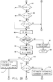
catalytic converter 18 efficiency or any reduction in the accuracy of the pre-converter oxygen sensor or other emission control hardware components. - Specifically, the routine of Figures 2a-2c is periodically executed starting at
step 60, for example approximately every 12.5 milliseconds while thecontroller 30 is operating. The routine proceeds fromstep 60 tostep 62 to determine if START FLAG is clear, indicating that the routine has not been executed since non-volatile RAM ofcontroller 30 was most recently cleared. Certain variables must, in this embodiment, hold their values aftercontroller 30 stops executing engine control, such as when ignition power is removed fromcontroller 30. Such variables must be stored in non-volatile RAM and must be initialised during the first iteration of the present pass through routine after non-volatile RAM has been cleared, as indicated by non-volatile RAM variable START FLAG being cleared. - For example, if at
step 62 START FLAG is clear, the routine moves tostep 64 to initialise non-volatile RAM variables. Specifically, each of a set of values ε(.), to be described, are set to zero, OLDSTATE is set to a value RICH representing a rich air/fuel ratio condition, START FLAG is set to one and oxygen sensor ready flag RFLAG is cleared indicating the oxygen sensor may not be ready to be used as a control input, as is described below. - After initialising these non-volatile RAM variables, or if START FLAG was determined at
step 62 to be set, the routine moves to step 66 to set MODE in accordance with the current engine operating condition as the one of a class of modes most accurately describing the current engine operating state. For example, in this embodiment, the engine operating state may be classified as one of the following: idle, deceleration, cruise, light acceleration, and heavy acceleration. - Engine operating parameters used to indicate the engine mode may include engine speed or change in engine speed, both derived in a conventional manner from signal RPM, and engine load and change in engine load, both of which may be derived in a conventional manner from signal MAP. By comparing these input parameters or other engine parameters generally known to indicate the engine operating level to predetermined parameter ranges, a classification may be made as to the operating mode of the engine. MODE is then set at
step 66 to a value to indicate this mode. - After setting MODE, the routine moves to step 68 to read V, the voltage magnitude of the output signal of post-converter exhaust
gas oxygen sensor 24. The routine then determines Vf, a filtered version of V, atstep 70 by passing V through a conventional first order filter as follows:

in which af is a first order filter coefficient set close to unity in this embodiment, for example between 0.8 and 0.9, to provide moderate first order filtering of the signal V. - After filtering V at
step 70, the routine moves to steps 72 - 80 to determine whether conditions are appropriate for proceeding with the compensation of the routine. The routine first checks coolant temperature atstep 72 by reading signal TEMP and comparing it to a predetermined temperature threshold, forty degrees Celsius in this embodiment. - If TEMP is below this threshold, it is assumed the
engine 10 is of insufficient temperature to heat the oxygen sensor 24 (Figure 1) to its operational temperature. As is generally known in the art conventional ZrO2 sensors must be heated up to a characteristic temperature before providing stable and accurate oxygen content information. Such sensors may be heated or may rely on engine heat, such as that passed to the sensor in the form of exhaust gas heat energy, to elevate their temperature. -
Step 72 is provided in the event the sensor relies on engine heat for its heating. If the engine coolant temperature is not elevated to To degrees, then it is determined, such as through a conventional calibration step, that theoxygen sensor 24 is not likely to be operational. In this case the analysis carried out by this routine is avoided and the routine passes to step 126 to reset OLDSTATE to a default setting of RICH and then exits viastep 94. - On the other hand, if TEMP does exceed To, the routine moves from
step 72 to step 74 to determine if the fuel control loop is operating in closed-loop control as indicated by flag CLFLAG, which is set to one when such closed-loop control is active. If closed-loop control is not active, theupstream oxygen sensor 22 is not being used for engine air/fuel ratio control and, as such, the routine need not update Vref. In such a case, the routine moves to step 126. - However, if CLFLAG is set, the routine moves to step 76 to compare a closed-loop correction factor CORRCL to a calibrated value Δ, set at 16 in this embodiment. CORRCL is a closed-loop correction value used, in accordance with generally known closed-loop air/fuel ratio control practice, to compensate for deviations between actual air/fuel ratio and a desired air/fuel ratio, such as the stoichiometric ratio. CORRCL ranges in magnitude from 0 to 255 in this embodiment, with 128 corresponding to a zero correction value. CORRCL is set up rapidly to increase or decrease as necessary to provide air/fuel ratio compensation and is reduced towards zero slowly through the compensation provided by a second compensation value, such as a block learn value.
- The block learn value responds more slowly to air/fuel ratio deviations than does CORRCL. Both values are applied to fuel command FUEL in this embodiment to drive the actual air/fuel ratio towards the desired air/fuel ratio. Any deviation left uncompensated by the block learn value is addressed by the magnitude of the CORRCL such that, eventually, after an air/fuel ratio perturbation, CORRCL may be reduced to a zero compensation value through the gradual increase in the block learn compensation. The value Δ need not be fixed at 16 counts for all operating modes but may vary as a function of the mode currently active, as set at
step 66 of the routine. Typically, Δ ranges from six to sixteen counts over the modes of this embodiment. - Returning to step 76, if the magnitude of CORRCL is determined to have deviated from 128 by an amount exceeding Δ, then that conventional portion of air/fuel compensation of this embodiment is still responding to a significant deviation between actual and desired air/fuel ratio, such that the block learn value has not yet reduced the deviation to the extent necessary to reduce CORRCL close to 128. Under such conditions, the fine adjustment in the air/fuel ratio compensation provided is preferably deferred to allow only the more granular conventional compensation to compensate the air/fuel ratio deviation.
- Thus, the compensation is avoided when the magnitude of (CORRCL - 128) exceeds Δ, by moving from
step 76 to step 126. On the other hand, if the magnitude of CORRCL is less than or equal to Δ, the routine moves to step 78 to verify that closed-loop engine air/fuel ratio control around the stoichiometric ratio is active, such as by verifying that certain enabling conditions for such control are met. - For example, such closed-loop control will not be active if a failure mode exists, of the type known in the art, or if control modes such as acceleration enrichment, deceleration fuel cutoff or power enrichment are active. In the event that any of such modes are deemed to be active at
step 78, the routine avoids compensating Vref by moving to step 128. - However, if it is determined at
step 78 that the modes precluding closed-loop air/fuel ratio control around the stoichiometric ratio are not active, the routine continues to step 82 to check the status of RFLAG which, when set to one, indicates that thepost-converter oxygen sensor 24 is ready to be tested. If RFLAG is not set to one atstep 82, the routine moves tosteps sensor 24 is within a range bounded by upper voltage Eu and lower voltage El. - If the sensor output voltage magnitude is within that range, the sensor may be assumed to be of sufficient temperature to ensure a stable and accurate oxygen content indication thereby. A conventional ZrO2 sensor will exhibit an output voltage of low peak to peak amplitude, such as within the range bounded by Eu and El, when insufficiently heated for use in this control routine.
- As described, step 72 of the routine determines whether the engine temperature is sufficiently elevated for oxygen sensor signals to be accurate and stable.
Steps - Returning to
steps - After setting RFLAG to one at
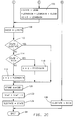
step 88, the routine moves to step 90 to compare TIMER, which monitors the amount of time between Vref adjustments of the routine to a predetermined value CORRECTION TIME, stored inROM 34 as the desired time between Vref correction in this embodiment. In this embodiment CORRECTION TIME is set as a function of MODE determined atstep 66. This provides compensation consistent with the needs of an event-driven closed-loop compensation system. For example, if event driven control is operating at high frequency, compensation should likewise operate at high frequency. Alternatively, if the engine is in a mode having low frequency control operation, compensation may have a larger CORRECTION TIME and thus a lower compensation frequency. Representative CORRECTION TIMES vary in this embodiment as a function of the various modes and their operating rates, generally from one to four seconds. - Returning to step 90, if TIMER is less than the CORRECTION TIME for the set mode, the routine moves to step 92 to increase TIMER by the present loop time, such as 12.5 milliseconds in this embodiment. The routine then exits via
step 94 to return to any prior routine which was being executed by thecontroller 30 at the time the routine of Figures 2a-2c was initiated. - Alternatively at
step 90, if TIMER exceeds or is equal to CORRECTION TIME, the routine moves to step 96 to reset TIMER to zero and then proceeds to step 98 to retrieve the value ε stored for the present MODE. A value ε is stored in non-volatile RAM for each mode. Each ε may then be updated and restored when the corresponding mode is active and a Vref correction is required, as is described below. - After obtaining a stored ε, the routine moves to
steps - If the output voltage of the post-converter oxygen sensor is within the range, no correction of Vref, the pre-converter reference voltage, is required. However, if the post-converter output voltage is outside the range, Vref is adjusted to drive the engine air/fuel ratio in direction to move the post-converter output voltage back into the range. In this embodiment, in which Vf has a range generally from zero to one volt, Vl may be selected as a value in the range of 0.57 - 0.59 volts and Vr may be selected as a value in the range of 0.59 - 0.62 volts.
- Returning to step 100, if Vf exceeds or is equal to Vr, the routine moves to step 102 to set the flag STATE to RICH, indicating the sensed rich condition for the present iteration. Additionally at
step 102, RICHGAIN is decreased by a small amount KRICH, such as zero to four counts in this embodiment, and the decreased RICHGAIN added to ε to provide an integral gain adjustment thereto to minimise the difference between Vf and the desirable range bounded by Vr and Vl. - Returning to step 100, if Vf is less than Vr, the routine moves to check the lean limit at
step 104 by comparing Vf to Vl, in which Vl is set in this embodiment to approximately 0.57 to 0.59 volts. If Vf is less than or equal to Vl atstep 104, the routine moves to step 106 to set flag STATE to LEAN, indicating the sensed lean condition. Additionally atstep 106, integral gain compensation is provided by adding KLEAN, set at a small value in this embodiment such as zero to five counts, to LEANGAIN and then by adding LEANGAIN to ε. After providing the integration compensation atstep - Alternatively, at
step 104, if Vf is greater than Vl, no Vref compensation is assumed to be needed and step 110 is executed to reset RICHGAIN and LEANGAIN to initial values RICHGAINo and LEANGAINo respectively. These initial values may range from one to five counts in the present embodiment. The routine then moves to step 126. -
Step 108, executed afterstep - Specifically,
step 112 is first executed to determine if the present STATE has changed over the most recent prior state as indicated by OLDSTATE. If the state is the same, no proportional compensation is necessary and such compensation is avoided by moving directly to step 120. Otherwise, compensation is provided by moving to step 114 to determine the direction of change in state. For example, if the present STATE is RICH, the lean to rich transition from the prior iteration of this routine to the present iteration must be compensated as shown atstep 118, at which a proportional rich gain PRICHGAIN is subtracted from ε. PRICHGAIN in this embodiment may be set at a value in the range from one to four counts. - Returning to step 114, if the transition was from rich to lean, the compensation of
step 116 is provided by adding PLEANGAIN, a lean proportional gain set in the range between one and six counts in the present embodiment, to ε. After providing the proportional gain of either ofsteps step 112, the routine moves to step 120 to store the adjusted ε in non-volatile RAM as a function of MODE. The routine then moves to step 122 to reduce Vref by the determined ε to drive Vref in a direction to maintain the post-converter sensed exhaust gas oxygen content at a level consistent with efficient conversion of the undesirable exhaust gas constituents, such as at a level at which Vf will be between Vl and Vr. - After adjusting Vref, the routine moves to step 124 to set OLDSTATE to the value STATE for use in the next iteration of the routine. The routine is then exited at
step 94 to return to any processes which may have been active prior to the start of the routine. - The disclosures in United States patent application no. 132,944, from which this application claims priority, and in the abstract accompanying this application are incorporated herein by reference.
Claims (10)
- A method of regulating the air/fuel ratio of an internal combustion engine including exhaust gas treatment means (18) in an engine exhaust gas path (16) through which engine exhaust gas passes, comprising the steps of generating an upstream oxygen content signal representing engine exhaust gas oxygen content at a first predetermined position (22) in the exhaust gas path; generating a downstream oxygen content signal representing engine exhaust gas oxygen content at a second predetermined position (24) in the exhaust gas path; comparing the downstream oxygen content signal to a predetermined signal range; adjusting a reference voltage level in a direction to drive the downstream oxygen content signal towards the predetermined signal range when the downstream oxygen content signal is not within the predetermined signal range; determining an oxygen content error signal as a difference between the reference voltage level and the upstream oxygen content signal; and determining a fuel command adjustment as a predetermined function of the oxygen content error signal.
- A method according to claim 1, comprising the steps of sensing predetermined engine operating parameters; selecting an engine operating mode from a predetermined set of modes as the mode most closely associated with an engine operating condition represented by the sensed predetermined engine operating parameters; and selecting from a stored set of reference voltage levels corresponding to the predetermined set of modes a reference voltage level corresponding to the selected engine operating mode; wherein the reference voltage level is adjusted in a direction to drive the downstream oxygen content signal towards the predetermined signal range when the downstream oxygen content signal is not within the predetermined signal range.
- A method according to claim 1 or 2, comprising the step of updating the selected reference voltage level by storing the adjusted selected reference voltage level with the stored set of reference levels.
- A method according to claim 1, 2 or 3, wherein the predetermined signal range represents a range of downstream oxygen content signal levels corresponding to a stoichiometric average engine air/fuel ratio.
- A method according to any preceding claim, comprising the step of generating a compensation deadband around the adjusted reference voltage level, extending a predetermined upper offset voltage above the adjusted reference voltage level and a predetermined lower offset below the adjusted reference voltage level; wherein the step of determining the oxygen content error signal determines an oxygen content error signal as an amount by which the upstream oxygen content signal lies outside the compensation deadband.
- A method according to claim 5, wherein the predetermined upper offset voltage equals the predetermined lower offset voltage.
- A method according to any preceding claim, wherein the exhaust gas treatment means (18) is disposed between the first and second predetermined positions (22,24) in the exhaust gas path, and wherein engine exhaust gas passes the first predetermined position (22) prior to passing the second predetermined position (24).
- A method according to any preceding claim, wherein the reference voltage level is adjusted by a predetermined adjustment value.
- A method according to any preceding claim, wherein the step of determining a fuel command adjustment includes the step of adjusting the magnitude of one of the group consisting of an engine inlet air quantity and an engine inlet fuel quantity in a direction to reduce the determined oxygen content error signal.
- An air/fuel ratio regulator for regulating the air/fuel ratio of an internal combustion engine including exhaust gas treatment means (18) in an engine exhaust gas path (16) through which engine exhaust gas passes, comprising an upstream oxygen sensor (22) for generating an upstream oxygen content signal representing engine exhaust gas oxygen content at a first predetermined position in the exhaust gas path; a downstream oxygen sensor (24) for generating a downstream oxygen content signal representing engine exhaust gas oxygen content at a second predetermined position in the exhaust gas path; and processing means (30) operative to compare the downstream oxygen content signal to a predetermined signal range, to adjust a reference voltage level in a direction to drive the downstream oxygen content signal towards the predetermined signal range when the downstream oxygen content signal is not within the predetermined signal range; to determine an oxygen content error signal as a difference between the reference voltage level and the upstream oxygen content signal; and to determine a fuel command adjustment as a predetermined function of the oxygen content error signal.
Applications Claiming Priority (2)
| Application Number | Priority Date | Filing Date | Title |
|---|---|---|---|
| US08/132,944 US5392598A (en) | 1993-10-07 | 1993-10-07 | Internal combustion engine air/fuel ratio regulation |
| US132944 | 1993-10-07 |
Publications (3)
| Publication Number | Publication Date |
|---|---|
| EP0647776A2 true EP0647776A2 (en) | 1995-04-12 |
| EP0647776A3 EP0647776A3 (en) | 1997-12-10 |
| EP0647776B1 EP0647776B1 (en) | 1999-12-15 |
Family
ID=22456293
Family Applications (1)
| Application Number | Title | Priority Date | Filing Date |
|---|---|---|---|
| EP94202697A Expired - Lifetime EP0647776B1 (en) | 1993-10-07 | 1994-09-20 | Air/fuel ratio regulation system for an internal combustion engine |
Country Status (4)
| Country | Link |
|---|---|
| US (1) | US5392598A (en) |
| EP (1) | EP0647776B1 (en) |
| AU (1) | AU665317B2 (en) |
| DE (1) | DE69422127T2 (en) |
Cited By (1)
| Publication number | Priority date | Publication date | Assignee | Title |
|---|---|---|---|---|
| RU2602025C2 (en) * | 2011-04-08 | 2016-11-10 | Форд Глобал Текнолоджиз, Ллк | Method (versions) and system for adjustment of air-fuel ratio |
Families Citing this family (21)
| Publication number | Priority date | Publication date | Assignee | Title |
|---|---|---|---|---|
| DE19545706C2 (en) * | 1995-12-07 | 1999-07-15 | Mannesmann Vdo Ag | Method for calibrating a lambda probe in an internal combustion engine |
| DE19642443C2 (en) * | 1996-10-15 | 2001-12-13 | Telefunken Microelectron | Process for controlling a controlled variable |
| FR2772078B1 (en) * | 1997-12-05 | 2000-02-18 | Renault | METHOD FOR CONTROLLING THE INJECTION OF AN INTERNAL COMBUSTION ENGINE |
| IT1306318B1 (en) * | 1998-07-16 | 2001-06-04 | Magneti Marelli Spa | AIR / FUEL RATIO CONTROL DEVICE OF THE MIXTURE SUPPLIED TO AN ENDOTHERMAL ENGINE |
| DE10025034A1 (en) * | 2000-05-20 | 2001-11-22 | Dmc2 Degussa Metals Catalysts | Method for operating an exhaust gas purification device on an Otto engine |
| WO2004093811A2 (en) * | 2003-04-22 | 2004-11-04 | Pharmacia Corporation | Compositions of a cyclooxygenase-2 selective inhibitor and a sodium ion channel blocker for the treatment of central nervous system damage |
| JP4107495B2 (en) * | 2003-08-27 | 2008-06-25 | 三菱電機株式会社 | Air-fuel ratio arithmetic unit |
| US7014906B2 (en) * | 2003-10-14 | 2006-03-21 | 3M Innovative Properties Company | Hook fastener and method of making |
| JP2006022772A (en) * | 2004-07-09 | 2006-01-26 | Mitsubishi Electric Corp | Air-fuel ratio control device for internal combustion engine |
| US7140360B2 (en) * | 2005-03-03 | 2006-11-28 | Cummins, Inc. | System for controlling exhaust emissions produced by an internal combustion engine |
| DE102009009516B4 (en) | 2008-02-25 | 2018-10-04 | GM Global Technology Operations LLC (n. d. Ges. d. Staates Delaware) | Motor motion detection system and method |
| US9695731B2 (en) * | 2011-06-24 | 2017-07-04 | Ford Global Technologies, Llc | System and methods for controlling air fuel ratio |
| US9109523B2 (en) | 2013-01-18 | 2015-08-18 | Ford Global Technologies, Llc | Methods and systems for humidity and PCV flow detection via an exhaust gas sensor |
| US9482189B2 (en) | 2013-09-19 | 2016-11-01 | Ford Global Technologies, Llc | Methods and systems for an intake oxygen sensor |
| US9328684B2 (en) | 2013-09-19 | 2016-05-03 | Ford Global Technologies, Llc | Methods and systems for an intake oxygen sensor |
| CN104454166B (en) * | 2013-09-25 | 2018-10-26 | 福特环球技术公司 | Method and system via exhaust sensor for humidity and PCV stream detections |
| US9957906B2 (en) * | 2013-11-06 | 2018-05-01 | Ford Gloabl Technologies, LLC | Methods and systems for PCV flow estimation with an intake oxygen sensor |
| US9322367B2 (en) | 2014-01-14 | 2016-04-26 | Ford Global Technologies, Llc | Methods and systems for fuel canister purge flow estimation with an intake oxygen sensor |
| US9234476B2 (en) | 2014-04-14 | 2016-01-12 | Ford Global Technologies, Llc | Methods and systems for determining a fuel concentration in engine oil using an intake oxygen sensor |
| US9441564B2 (en) | 2014-04-14 | 2016-09-13 | Ford Global Technologies, Llc | Methods and systems for adjusting EGR based on an impact of PCV hydrocarbons on an intake oxygen sensor |
| CN115726895B (en) * | 2022-11-23 | 2024-09-17 | 中国第一汽车股份有限公司 | Aging compensation method for upstream linear oxygen sensor of catalyst |
Family Cites Families (11)
| Publication number | Priority date | Publication date | Assignee | Title |
|---|---|---|---|---|
| JPS6033987B2 (en) * | 1978-05-02 | 1985-08-06 | トヨタ自動車株式会社 | Feedback air-fuel ratio control device |
| CH668620A5 (en) * | 1984-04-12 | 1989-01-13 | Daimler Benz Ag | METHOD FOR CHECKING AND ADJUSTING CATALYTIC EXHAUST GAS PURIFICATION PLANTS OF COMBUSTION ENGINES. |
| US4625698A (en) * | 1985-08-23 | 1986-12-02 | General Motors Corporation | Closed loop air/fuel ratio controller |
| US4817384A (en) * | 1986-08-13 | 1989-04-04 | Toyota Jidosha Kabushiki Kaisha | Double air-fuel ratio sensor system having improved exhaust emission characteristics |
| JPH0718366B2 (en) * | 1986-11-08 | 1995-03-06 | トヨタ自動車株式会社 | Air-fuel ratio controller for internal combustion engine |
| JP2611322B2 (en) * | 1988-04-09 | 1997-05-21 | 三菱自動車工業株式会社 | Air-fuel ratio control device for internal combustion engine and oxygen concentration sensor for air-fuel ratio control |
| DE4009901A1 (en) * | 1990-03-28 | 1991-10-02 | Bosch Gmbh Robert | METHOD AND DEVICE FOR MONITORING THE CONVERSION LEVEL OF A CATALYST IN THE EXHAUST SYSTEM OF AN INTERNAL COMBUSTION ENGINE |
| JPH0417747A (en) * | 1990-05-07 | 1992-01-22 | Japan Electron Control Syst Co Ltd | Air-fuel ratio control device for internal combustion engines |
| DE4128718C2 (en) * | 1991-08-29 | 2001-02-01 | Bosch Gmbh Robert | Method and device for regulating the amount of fuel for an internal combustion engine with a catalyst |
| US5282360A (en) * | 1992-10-30 | 1994-02-01 | Ford Motor Company | Post-catalyst feedback control |
| US5291673A (en) * | 1992-12-21 | 1994-03-08 | Ford Motor Company | Oxygen sensor system with signal correction |
-
1993
- 1993-10-07 US US08/132,944 patent/US5392598A/en not_active Expired - Lifetime
-
1994
- 1994-09-20 EP EP94202697A patent/EP0647776B1/en not_active Expired - Lifetime
- 1994-09-20 DE DE69422127T patent/DE69422127T2/en not_active Expired - Lifetime
- 1994-09-26 AU AU74202/94A patent/AU665317B2/en not_active Expired
Cited By (1)
| Publication number | Priority date | Publication date | Assignee | Title |
|---|---|---|---|---|
| RU2602025C2 (en) * | 2011-04-08 | 2016-11-10 | Форд Глобал Текнолоджиз, Ллк | Method (versions) and system for adjustment of air-fuel ratio |
Also Published As
| Publication number | Publication date |
|---|---|
| DE69422127T2 (en) | 2000-04-27 |
| AU7420294A (en) | 1995-04-27 |
| EP0647776B1 (en) | 1999-12-15 |
| EP0647776A3 (en) | 1997-12-10 |
| AU665317B2 (en) | 1995-12-21 |
| US5392598A (en) | 1995-02-28 |
| DE69422127D1 (en) | 2000-01-20 |
Similar Documents
| Publication | Publication Date | Title |
|---|---|---|
| EP0647776B1 (en) | Air/fuel ratio regulation system for an internal combustion engine | |
| CA2299933C (en) | Control device for an air-fuel ratio sensor | |
| US6629409B2 (en) | System and method for determining set point location for oxidant-based engine air/fuel control strategy | |
| EP0148107A2 (en) | Method and apparatus for torque control of an internal combustion engine as a function of exhaust smoke level | |
| JPH0339189B2 (en) | ||
| EP0466311A1 (en) | Method of on-board detection of automotive catalyst degradation | |
| US20020056310A1 (en) | Control method for gas concentration sensor | |
| EP1128043B1 (en) | Air-fuel ratio control of engine | |
| US20040103642A1 (en) | Method for purifying exhaust gas of an internal combustion engine | |
| EP0659994B1 (en) | Closed-loop control of a diesel engine | |
| JPH0694827B2 (en) | A method for optimizing the fuel to air ratio in the unsteady state of an internal combustion engine. | |
| US6964160B2 (en) | System and method for controlling catalyst storage capacity | |
| NL8802761A (en) | METHOD FOR CONTROLLING THE COMBUSTION AIR AND DEVICE FOR CARRYING OUT THE METHOD | |
| WO1994015085A1 (en) | Oxygen sensor system with signal correction | |
| GB2380430A (en) | A method for quantifying the amount of oxygen stored in an emission control device. | |
| CA1161524A (en) | Closed loop air/fuel ratio control system with oxygen sensor signal compensation | |
| US7007461B2 (en) | System and method for controlling catalyst storage capacity | |
| EP0676003B1 (en) | Oxygen sensor deterioration detection | |
| JPH06299886A (en) | Feedback control system and control method | |
| US5251604A (en) | System and method for detecting deterioration of oxygen sensor used in feedback type air-fuel ratio control system of internal combustion engine | |
| US12577896B2 (en) | Method for operating a drive device and corresponding drive device | |
| GB2345142A (en) | Method for operating a NOx sensor in the exhaust system of an internal combustion engine | |
| JPS61232349A (en) | Air-fuel ratio controller for internal-combustion engine | |
| GB2273571A (en) | Multiple exhaust gas oxygen sensor system for IC engine with catalytic converter | |
| US5251605A (en) | Air-fuel control having two stages of operation |
Legal Events
| Date | Code | Title | Description |
|---|---|---|---|
| PUAI | Public reference made under article 153(3) epc to a published international application that has entered the european phase |
Free format text: ORIGINAL CODE: 0009012 |
|
| AK | Designated contracting states |
Kind code of ref document: A2 Designated state(s): DE FR GB IT |
|
| PUAL | Search report despatched |
Free format text: ORIGINAL CODE: 0009013 |
|
| AK | Designated contracting states |
Kind code of ref document: A3 Designated state(s): DE FR GB IT |
|
| 17P | Request for examination filed |
Effective date: 19980610 |
|
| 17Q | First examination report despatched |
Effective date: 19980720 |
|
| GRAG | Despatch of communication of intention to grant |
Free format text: ORIGINAL CODE: EPIDOS AGRA |
|
| GRAG | Despatch of communication of intention to grant |
Free format text: ORIGINAL CODE: EPIDOS AGRA |
|
| GRAH | Despatch of communication of intention to grant a patent |
Free format text: ORIGINAL CODE: EPIDOS IGRA |
|
| GRAH | Despatch of communication of intention to grant a patent |
Free format text: ORIGINAL CODE: EPIDOS IGRA |
|
| GRAA | (expected) grant |
Free format text: ORIGINAL CODE: 0009210 |
|
| ITF | It: translation for a ep patent filed | ||
| AK | Designated contracting states |
Kind code of ref document: B1 Designated state(s): DE FR GB IT |
|
| REF | Corresponds to: |
Ref document number: 69422127 Country of ref document: DE Date of ref document: 20000120 |
|
| ET | Fr: translation filed | ||
| PLBE | No opposition filed within time limit |
Free format text: ORIGINAL CODE: 0009261 |
|
| STAA | Information on the status of an ep patent application or granted ep patent |
Free format text: STATUS: NO OPPOSITION FILED WITHIN TIME LIMIT |
|
| 26N | No opposition filed | ||
| REG | Reference to a national code |
Ref country code: GB Ref legal event code: IF02 |
|
| PG25 | Lapsed in a contracting state [announced via postgrant information from national office to epo] |
Ref country code: IT Free format text: LAPSE BECAUSE OF NON-PAYMENT OF DUE FEES Effective date: 20050920 |
|
| REG | Reference to a national code |
Ref country code: GB Ref legal event code: 732E Free format text: REGISTERED BETWEEN 20090226 AND 20090304 |
|
| REG | Reference to a national code |
Ref country code: GB Ref legal event code: 732E Free format text: REGISTERED BETWEEN 20090305 AND 20090311 |
|
| REG | Reference to a national code |
Ref country code: GB Ref legal event code: 732E Free format text: REGISTERED BETWEEN 20091029 AND 20091104 |
|
| REG | Reference to a national code |
Ref country code: GB Ref legal event code: 732E Free format text: REGISTERED BETWEEN 20091105 AND 20091111 |
|
| PGFP | Annual fee paid to national office [announced via postgrant information from national office to epo] |
Ref country code: DE Payment date: 20130918 Year of fee payment: 20 |
|
| PGFP | Annual fee paid to national office [announced via postgrant information from national office to epo] |
Ref country code: FR Payment date: 20130910 Year of fee payment: 20 Ref country code: GB Payment date: 20130918 Year of fee payment: 20 |
|
| REG | Reference to a national code |
Ref country code: DE Ref legal event code: R071 Ref document number: 69422127 Country of ref document: DE |
|
| REG | Reference to a national code |
Ref country code: DE Ref legal event code: R071 Ref document number: 69422127 Country of ref document: DE |
|
| REG | Reference to a national code |
Ref country code: GB Ref legal event code: PE20 Expiry date: 20140919 |
|
| PG25 | Lapsed in a contracting state [announced via postgrant information from national office to epo] |
Ref country code: DE Free format text: LAPSE BECAUSE OF EXPIRATION OF PROTECTION Effective date: 20140923 |
|
| PG25 | Lapsed in a contracting state [announced via postgrant information from national office to epo] |
Ref country code: GB Free format text: LAPSE BECAUSE OF EXPIRATION OF PROTECTION Effective date: 20140919 |