EP0647977B1 - Zirkular polarisierte Mikrozellen-Antenne - Google Patents
Zirkular polarisierte Mikrozellen-Antenne Download PDFInfo
- Publication number
- EP0647977B1 EP0647977B1 EP94113283A EP94113283A EP0647977B1 EP 0647977 B1 EP0647977 B1 EP 0647977B1 EP 94113283 A EP94113283 A EP 94113283A EP 94113283 A EP94113283 A EP 94113283A EP 0647977 B1 EP0647977 B1 EP 0647977B1
- Authority
- EP
- European Patent Office
- Prior art keywords
- dipole
- antenna
- circularly polarized
- conductor bar
- conductor
- Prior art date
- Legal status (The legal status is an assumption and is not a legal conclusion. Google has not performed a legal analysis and makes no representation as to the accuracy of the status listed.)
- Expired - Lifetime
Links
- 239000004020 conductor Substances 0.000 claims abstract description 47
- 230000010363 phase shift Effects 0.000 claims abstract description 7
- 230000000712 assembly Effects 0.000 claims 3
- 238000000429 assembly Methods 0.000 claims 3
- 230000002093 peripheral effect Effects 0.000 claims 1
- 230000001413 cellular effect Effects 0.000 description 12
- 238000004891 communication Methods 0.000 description 6
- 230000005540 biological transmission Effects 0.000 description 5
- 230000010287 polarization Effects 0.000 description 4
- 125000006850 spacer group Chemical group 0.000 description 3
- 238000005259 measurement Methods 0.000 description 2
- XAGFODPZIPBFFR-UHFFFAOYSA-N aluminium Chemical compound [Al] XAGFODPZIPBFFR-UHFFFAOYSA-N 0.000 description 1
- 229910052782 aluminium Inorganic materials 0.000 description 1
- 239000003990 capacitor Substances 0.000 description 1
- 230000010267 cellular communication Effects 0.000 description 1
- 230000001419 dependent effect Effects 0.000 description 1
- 238000013461 design Methods 0.000 description 1
- 230000005684 electric field Effects 0.000 description 1
- 239000011152 fibreglass Substances 0.000 description 1
- 238000012423 maintenance Methods 0.000 description 1
- 230000013011 mating Effects 0.000 description 1
- 230000005404 monopole Effects 0.000 description 1
- 230000005855 radiation Effects 0.000 description 1
- 238000010079 rubber tapping Methods 0.000 description 1
- 238000001228 spectrum Methods 0.000 description 1
- 238000010561 standard procedure Methods 0.000 description 1
- 230000001360 synchronised effect Effects 0.000 description 1
Images


Classifications
-
- H—ELECTRICITY
- H01—ELECTRIC ELEMENTS
- H01Q—ANTENNAS, i.e. RADIO AERIALS
- H01Q1/00—Details of, or arrangements associated with, antennas
- H01Q1/12—Supports; Mounting means
- H01Q1/22—Supports; Mounting means by structural association with other equipment or articles
- H01Q1/24—Supports; Mounting means by structural association with other equipment or articles with receiving set
- H01Q1/241—Supports; Mounting means by structural association with other equipment or articles with receiving set used in mobile communications, e.g. GSM
- H01Q1/246—Supports; Mounting means by structural association with other equipment or articles with receiving set used in mobile communications, e.g. GSM specially adapted for base stations
-
- H—ELECTRICITY
- H01—ELECTRIC ELEMENTS
- H01Q—ANTENNAS, i.e. RADIO AERIALS
- H01Q19/00—Combinations of primary active antenna elements and units with secondary devices, e.g. with quasi-optical devices, for giving the antenna a desired directional characteristic
- H01Q19/10—Combinations of primary active antenna elements and units with secondary devices, e.g. with quasi-optical devices, for giving the antenna a desired directional characteristic using reflecting surfaces
-
- H—ELECTRICITY
- H01—ELECTRIC ELEMENTS
- H01Q—ANTENNAS, i.e. RADIO AERIALS
- H01Q21/00—Antenna arrays or systems
- H01Q21/06—Arrays of individually energised antenna units similarly polarised and spaced apart
- H01Q21/08—Arrays of individually energised antenna units similarly polarised and spaced apart the units being spaced along or adjacent to a rectilinear path
- H01Q21/10—Collinear arrangements of substantially straight elongated conductive units
-
- H—ELECTRICITY
- H01—ELECTRIC ELEMENTS
- H01Q—ANTENNAS, i.e. RADIO AERIALS
- H01Q21/00—Antenna arrays or systems
- H01Q21/24—Combinations of antenna units polarised in different directions for transmitting or receiving circularly and elliptically polarised waves or waves linearly polarised in any direction
- H01Q21/26—Turnstile or like antennas comprising arrangements of three or more elongated elements disposed radially and symmetrically in a horizontal plane about a common centre
Definitions
- the present invention relates to circularly polarized antennae and, more particularly, to a circularly polarized microcell antenna that requires only a single feed-line to radiate circularly polarized electromagnetic signals from a pair of crossed dipoles.
- each cellular telephone transmission site Associated with each cellular telephone transmission site are a number of antennae for transmitting signals in the cellular telephone frequency band of the electromagnetic spectrum. It is common in the cellular telephone communications industry for these antennae to transmit these signals in a circularly polarized manner.
- Circular polarization of electromagnetic signals transmitted from cellular telephone antennae may be achieved with a pair of crossed, one-half wavelength, dipoles that are fed with equal currents from a synchronous source so as to result in quadrature phasing.
- the standard method of feeding these dipole pairs is to run a separate feed-line to each dipole pair, with the two feed-lines having a 90° phase length difference between them.
- running a separate feed-line to each dipole pair can be both cumbersome and costly with regard to equipment expenditures and maintenance. It also reduces the impedance bandwidth of the antenna.
- GB-A-2 034 125 shows a coaxial phased array antenna which has a pair of crossed-dipole elements positioned within an inner cavity and four monopole elements symmetrically arranged in an outer cavity.
- the pair of crossed-dipole elements is centered within the inner cavity and operated by the elements of the outer cavity which realizes a phase shifting network.
- Two dipoles of the crossed-dipole elements are fed respectively by a coaxial line.
- the external phase shifting network provides the 90 degree phasing to generate circularly polarized radiation.
- the present invention contemplates a circularly polarized microcell antenna employing a pair of crossed dipoles that are fed through a single feed-line.
- This antenna comprises a pair of crossed dipoles and a pair of phase loop elements which are mounted in a reflector box.
- the reflector box is connected to a single feed-line through a connector, and the reflector box is impedance matched with the connector.
- the primary dipole in the pair of crossed dipoles is electrically connected to the reflector box at designated one-quarter wavelength locations.
- the secondary dipole in the pair of crossed dipoles is electrically connected to the primary dipole via the phase loop elements.
- the phase loop elements are connected between the pair of crossed dipoles to obtain the required quadrature phasing.
- the primary objective of the present invention is to provide a circularly polarized microcell antenna that employs a pair of crossed dipoles which are fed through a single feed-line so as to radiate circularly polarized electromagnetic signals.
- Figure 1 is a top view of a fully assembled circularly polarized microcell antenna according to the present invention taken along line 1-1 of Figure 2.
- Figure 2 is a partial breakaway side view of the fully assembled circularly polarized microcell antenna shown in Figure 1, taken along line 2-2 of Figure 1.
- Figure 3 is a top view of the circularly polarized microcell antenna shown in Figure 1 with the radome removed, taken along line 3-3 of Figure 4.
- Figure 4 is a partial breakaway side view of the circularly polarized microcell antenna shown in Figure 3, taken along line 4-4 of Figure 3.
- Figure 5 is a top view of the reflector box used in the circularly polarized microcell antenna shown in Figure 1, taken along line 5-5 of Figure 6.
- Figure 6 is a side view of the reflector box shown in Figure 5, taken along line 6-6 of Figure 5.
- Figure 7 is a bottom view of the conductor bar used in the circularly polarized microcell antenna shown in Figure 1, taken along line 7-7 of Figure 8.
- Figure 8 is a side view of the conductor bar shown in Figure 7, taken along line 8-8 of Figure 7.
- Figure 9 is a top view of the trim element used in the circularly polarized microcell antenna shown in Figure 1, taken along line 9-9 of Figure 10.
- Figure 10 is a side view of the trim element shown in Figure 9, taken along line 10-10 of Figure 9.
- Figure 11 is a side view of a standoff used in the circularly polarized microcell antenna shown in Figure 1, taken along line 11-11 of Figure 12.
- Figure 12 is an end view of the standoff shown in Figure 11, taken along line 12-12 of Figure 11.
- Figure 13 is a top view of a dipole arm used in the circularly polarized microcell antenna shown in Figure 1.
- Figure 14 is a top view of a phase loop element used in the circularly polarized microcell antenna shown in Figure 1.
- Figure 15 is a top view of a dipole assembly used in the circularly polarized microcell antenna shown in Figure 1, taken along line 15-15 of Figure 16.
- Figure 16 is a side view of the dipole assembly shown in Figure 15, taken along line 16-16 of Figure 15.
- Figure 17 shows a horizontal beamwidth pattern of the circularly polarized microcell antenna shown in Figure 1, taken at 824 MHz.
- Figure 18 shows a horizontal beamwidth pattern of the circularly polarized microcell antenna shown in Figure 1, taken at 859 MHz.
- Figure 19 shows a horizontal beamwidth pattern of the circularly polarized microcell antenna shown in Figure 1, taken at 894 MHz.
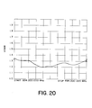
- Figure 20 is a graph of the voltage standing wave ratio of the circularly polarized microcell antenna shown in Figure 1, taken over the range from 824 MHz to 894 MHz.
- FIG. 1 and 2 there is shown a top and a side view, respectively, of a fully assembled circularly polarized microcell antenna 10 according to the present invention.
- the antenna 10 is shown having a radome 12 that is secured to a reflector box 14 (having a bottom 15 and side walls 17) by a plurality of mounting screws 16.
- the radome 12 is secured to the reflector box 14 in this manner so as to shield the inside of the box 14 from the elements, since the antenna 10 is generally deployed outdoors.
- a pair of crossed dipoles are mounted (see Figures 3 and 4).
- a pair of mounting brackets 18 and an electrical connector 20 Secured to the bottom of the reflector box 14 are a pair of mounting brackets 18 and an electrical connector 20.
- the mounting brackets 18 are used to secure the antenna 10 at a transmission site, generally a transmission tower.
- the electrical connector 20, typically a coaxial connector, allows a single feed-line to be electrically connected to the pair of crossed dipoles.
- the mounting brackets 18 are secured to the reflector box 14 with bolts 19, while the electrical connector 20 is secured to the reflector box 14 with screws 21.
- FIG. 3 and 4 there is shown a top and a side view, respectively, of the circularly polarized microcell antenna 10 with the radome 12 removed.
- the antenna 10 is shown having a conductor bar 22, typically a microstrip line conductor, that is electrically connected at one end to the center conductor 24 of the electrical connector 20.
- This electrical connection is made by mating the center conductor 24 with a hole 26 (see Figure 7) which has been vertically bored through the conductor bar 22, and then securing the center conductor 24 within the hole 26 by tightening a set screw 28.against the center conductor 24.
- the set screw 28 is positioned in a threaded hole 30 (see Figure 8) which has been horizontally bored into the side of the conductor bar 22 such that it is intersecting with the hole 26.
- the other end of the conductor bar 22 is secured to the reflector box 14 through a spacer 32 with a screw 34.
- the screw 34 mates with a threaded hole 35 (see Figure 7) which has been vertically bored through the conductor bar 22.
- the spacer 32, along with all the other components in the antenna 10 except the radome 12 which is preferably made of fiberglass, is made of an electrically conductive material, preferably irridited aluminum. Thus, an electrical connection is made between the conductor bar 22 and the reflector box 14 through the spacer 32.
- a countersunk hole 40 (see Figure 7) is vertically bored through the conductor bar 22 such that one end of a first standoff 36 may be secured thereto with a screw 38 without electrical contact being made with the reflector box 14.
- a second standoff 42 is secured to the reflector box 14 with a screw 44. Both ends of the first standoff 36 and the second standoff 42 have threaded holes 39 (see Figures 11 and 12) formed therein which allow the screws 38, 44, respectively, to mate therewith. Since, as previously described, the components in the antenna 10 are made of an electrically conductive material, an electrical connection is made between the first standoff 36 and the conductor bar 22 and between the second standoff 42 and the reflector box 14.
- the shell casing of the electrical connector 20 is electrical ground, and the electrical connector 20 is secured to the reflector box 14 so as to form an electrical connection therebetween.
- the reflector box 14 is considered to be an electrical ground with respect to the center conductor 24.
- the first standoff 36 and the second standoff 42 are secured at designated one-quarter wavelength locations on the conductor bar 22 and the reflector box 14, respectively, with respect to a standing wave that is generated along the conductor bar 22, and hence within the reflector box 14, from a signal supplied by the single feed-line.
- the first standoff 36 and the second standoff 42 are secured to the conductor bar 22 and the reflector box 14, respectively, at locations where the voltage component of the standing wave is at its peak.
- the electrical connector 20, and hence the single feed-line typically have a characteristic impedance of 50 ⁇ .
- a trim element 46 is secured to the conductor bar 22 so as to act as a capacitor or an impedance transformer in bringing the impedance of the antenna 10 in conformance with that of the electrical connector 20.
- the trim element 46 is secured to the conductor bar 22 with several screws 48.
- the screws 48 mate with corresponding threaded holes 50 (see Figure 7) which have been vertically bored into the conductor bar 22.
- FIG. 5 and 6 there is shown a top and a side view, respectively, of the reflector box 14 with the location of the mounting holes for the radome 12, the mounting brackets 18, the electrical connector 20, the conductor bar 22, and the second standoff 42 indicated.
- FIGs 7 and 8 there is shown a bottom and a side view, respectively, of the conductor bar 22 with the location of the holes for the center conductor 24, the first standoff 36, and the trim element 46 indicated.
- FIGs 9 and 10 there is shown a top and a side view, respectively, of the trim element 46 with the location of the mounting holes to the conductor bar 22 indicated.
- both the first standoff 36 and the second standoff 42 there are secured a pair of dipole arms 52. These two dipole arms 52 are secured to their respective standoffs 36,42 with screws 54 that mate with the threaded holes 39 (see Figures 11 and 12) formed in the ends of the standoffs 36,42. These two dipole arms 52 form the primary dipole in the pair of crossed dipoles.
- each third standoff 58 Secured to each dipole arm 52 forming the primary dipole is a third standoff 58 which in turn has one end of a phase loop element 56 secured thereto.
- Each third standoff 58 is secured to each primary dipole arm 52 with a screw 60
- each phase loop element 56 is secured to each third standoff 58 with a screw 62.
- each third standoff 58 has threaded holes 64 (see Figures 11 and 12) formed therein which mate with the screws 60, 62.
- the fourth standoffs 66 only differ in their respective lengths.
- Figures 11 and 12 all of the elements, except the exact lengths, of the first standoff 36, the second standoff 42, the third standoffs 58, and the fourth standoffs 66 are shown.
- each phase loop element 56 there is secured a fourth standoff 66 which in turn has a secondary dipole arm 68 secured thereto.
- Each fourth standoff 66 is secured to each phase loop element 56 with a screw 70
- each secondary dipole arm 68 is secured to each fourth standoff 66 with a screw 72.
- each fourth standoff 66 is physically identical to each third standoff 58, although they have been designated differently for purposes of figure clarity.
- each fourth standoff 66 has threaded holes 64 (see Figures 11 and 12) formed therein which mate with the screws 70, 72.
- each secondary dipole arm 68 is physically identical to each primary dipole arm 52, although they have been designated differently for purposes of figure clarity. It should further be noted that these two secondary dipole arms 66 form the secondary dipole of the pair of crossed dipoles.
- FIG. 13 there is shown a top view of a primary 52 and a secondary 68 dipole arm with the location of the mounting holes to the standoffs 36,42,58,66 indicated.
- FIG 14. there is shown a top view of a phase loop element 56 with the location of the mounting holes to the standoffs 58,66 indicated.
- FIG. 15 and 16 there is shown a top and a side view, respectively, of a dipole assembly 74, of which there are two in the antenna 10, having a primary dipole arm 52, a secondary dipole arm 68, a third standoff 58, a phase loop element 56, a fourth standoff 66, mounting screws 54,60,62,70,72, and either a first standoff 36 or a second standoff 42.
- the length difference between the first standoff 36 and the second standoff 42 is such that all of the dipole arms 52,68 must lie in the same vertical plane.
- the second standoff 42 is longer than the first standoff 36 so as to compensate for their different mounting arrangements (ie. the first standoff 36 is mounted to the conductor bar 22, while the second standoff 42 is mounted to the reflector box 14).
- the most critical aspect of the antenna 10 is the dimensioning of specific component parts, namely the dipole arms 52,68, the standoffs 36,42,58,66, and the phase loop elements 56.
- the center of the operating frequency range of the antenna 10 must be determined.
- the operating frequency band ranges from 824 MHz to 894 MHz.
- the center of the operating frequency range is 859 MHz, which corresponds to a 13.7402 inch wavelength.
- one-half wavelength dipoles requires that the effective distance, or length, between the feed point on each dipole arm 52,68 and the end of each dipole arm 52,68 be one-quarter of the above said wavelength.
- Each arm of the secondary dipole is fed by tapping the standing wave signal from a corresponding arm in the primary dipole. This signal is tapped through a pair of identical phasing loops, one for each arm, each comprising a phase loop element 56, a third standoff 58, and a fourth standoff 66.
- each phasing loop In order for the antenna 10 to achieve circular polarization, each phasing loop must provide a one-quarter wavelength delay, or a 90° phase shift, between the primary dipole arm 52 and the corresponding secondary dipole arm 68.
- the dimensions of each phasing loop must have an effective length of one-quarter of the above said wavelength. That is, the combined effective lengths of the phase loop element 56, the third standoff 58, and the fourth standoff 66 must be equal to one-quarter of the above said wavelength.
- the effective lengths of the phasing loops and the dipole arms 52,68 are largely dependent upon the current flow through these component parts, which is a function of component cross-sectional area and component geometry. Thus, the effective lengths of the phasing loops and the dipole arms 52,68 are often determined through experimental measurements rather than through pure physical dimensioning. It should also be noted that, although the circularly polarized microcell antenna 10 has been described herein as being used for cellular communications, the antenna concepts described herein may also be applied to other frequency bands with only dimensional changes being required.
- the operating frequency band for cellular telephone communications ranges from 824 MHz to 894 MHz, with the center frequency at 859 MHz. This corresponds to a 13.7402 inch wavelength.
- the effective length (inside dimension) of the phase loop element 56 chosen to be 1.248 inches, the effective length of both the third 58 and the fourth 66 standoffs have been determined to be 1.410 inches for a total of 4.068 inches, or 0.296 wavelengths.
- This actual effective wavelength of 0.296 wavelengths differs from a theoretical effective wavelength of 0.250 wavelengths, or one-quarter of the above said wavelength, due to the above-described component part dependence on current flow, which is a function of component cross-sectional area and component geometry.
- the actual effective wavelength of 0.296 wavelengths was determined by measuring the radiated phase from both dipoles in an actual circularly polarized microcell antenna 10 and adjusting the effective length of both the third 58 and the fourth 66 standoffs accordingly to achieve a 90° phase shift.
- the effective length of the dipole arms 52,68 have been similarly determined to be 3.564 inches, or 0.259 wavelengths.
- the dipole arms 52,68 are spaced off the conductor bar 22 and the reflector box 14 by the first standoff 36 and the second standoff 42, respectively. Also by measurement, the effective length of the first standoff 36 has been determined to be 2.871 inches, or 0.208 wavelengths, while the effective length of the second standoff 42 has been determined to be 3.281 inches, or 0.238 wavelengths. It should be noted that the difference between the effective length of the first standoff 36 and the effective length of the second standoff 42 is due to their different mounting arrangements.
- the circularly polarized microcell antenna 10 will achieve circular polarization of radiated signals in the cellular telephone communications frequency band by providing a one-quarter wavelength delay, or a 90° phase shift, in each phasing loop.
- measured horizontal beamwidth patterns of the circularly polarized microcell antenna 10 just described are shown at 824 MHz, 859 MHz, and 894 MHz, respectively. From these patterns, it can be seen that the 3 dB beamwidth of the antenna 10 over the cellular frequency band is approximately 75°.
- a graph of the measured voltage standing wave ratio (VSWR) of the circularly polarized microcell antenna 10 just described is shown over the range from 824 MHz to 894 MHz. According to industry standards, a VSWR of under 1.5, which is demonstrated here, indicates a good impedance match.
- the circularly polarized microcell antenna 10 described herein can radiate circularly polarized electromagnetic signals having a horizontal beamwidth of 75° with a VSWR of less than 1.5 over the cellular frequency band.
Landscapes
- Engineering & Computer Science (AREA)
- Computer Networks & Wireless Communication (AREA)
- Variable-Direction Aerials And Aerial Arrays (AREA)
- Input Circuits Of Receivers And Coupling Of Receivers And Audio Equipment (AREA)
- Details Of Aerials (AREA)
- Aerials With Secondary Devices (AREA)
Claims (7)
- Zirkular polarisierte Antenne (10) zum Abstrahlen zirkular polarisierter elektromagnetischer Energie, wobei die Antenne ein elektrisch leitendes Gehäuse (14), das eine Grundplatte (15) und am äußeren Umfang befindliche Seitenwände (17) besitzt, die sich von der Grundplatte aufwärts erstrecken, um die elektromagnetische Energie aus dem Inneren zu reflektieren, und zwei Dipolbaugruppen umfasst, die innerhalb des leitenden Gehäuses angeordnet sind, dadurch gekennzeichnet, dass die Antenne (10) desweiteren umfasst:einen elektrischen Verbinder (20), der einen elektrischen Leiter (24) besitzt, der von einer elektrisch auf Masse liegenden Abschirmung umgeben ist, wobei die Abschirmung am Gehäuse (14) befestigt wird, so dass zwischen diesen eine elektrische Verbindung hergestellt wird,eine Leiterschiene (22), die an einem ersten Ende mit dem elektrischen Leiter (24) und an einem zweiten Ende mit dem Gehäuse (14) verbunden ist, so dass darin eine Stehwelle erzeugt werden kann,eine erste der zwei Dipolbaugruppen, die einen ersten Primärdipolarm (52) und einen ersten Sekundärdipolarm (68) besitzt, die über eine erste Phasenrückkopplung (56) verbunden sind, um zwischen ihnen eine 90°-Phasenverschiebung zu erzeugen, wobei der erste Primärdipolarm (52) an der Leiterschiene (22) befestigt ist, so dass dazwischen eine elektrische Verbindung hergestellt wird, undeine zweite der zwei Dipolbaugruppen, die einen zweiten Primärdipolarm (52) und einen zweiten Sekundärdipolarm (68) besitzt, die über eine zweite Phasenrückkopplung (56) verbunden sind, um zwischen ihnen eine 90°-Phasenverschiebung zu erzeugen, wobei der zweite Primärdipolarm (52) am Gehäuse (14) befestigt ist, so dass dazwischen eine elektrische Verbindung hergestellt wird.
- Antenne nach Anspruch 1, dadurch gekennzeichnet, dass ein Abstimmelement (46) bereitgestellt wird, welches elektrisch mit der Leiterschiene (22) verbunden ist, um eine Impedanzanpassung zwischen dem Gehäuse (14), der Leiterschiene (22), der ersten Dipolbaugruppe und der zweiten Dipolbaugruppe zum elektrischen Verbinder (20) vorzunehmen.
- Antenne nach Anspruch 2, dadurch gekennzeichnet, dass das Abstimmelement (46) an der Leiterschiene (22) befestigt wird.
- Antenne nach Anspruch 1, dadurch gekennzeichnet, dass der elektrische Verbinder (20) ein Koaxialverbinder ist, der einen Mittenleiter (24) besitzt, welcher von einer elektrisch auf Masse liegenden Abschirmung umgeben ist.
- Antenne nach Anspruch 1, dadurch gekennzeichnet, dass die Leiterschiene (22) ein Mikrostreifenleiter ist.
- Antenne nach Anspruch 1, dadurch gekennzeichnet, dass die erste Dipolbaugruppe bezogen auf eine sich in der Leiterschiene (22) ausbildende Stehwelle an einer bestimmten Viertelwellenlängen-Position auf der Leiterschiene (22) befestigt wird.
- Antenne nach Anspruch 1, dadurch gekennzeichnet, dass der erste Primärdipolarm (52) und der erste Sekundärdipolarm (68) jeweils eine wirksame Länge von einem Viertel einer Wellenlänge bezogen auf eine sich in der Leiterschiene (22) ausbildende Stehwelle aufweisen.
Applications Claiming Priority (2)
| Application Number | Priority Date | Filing Date | Title |
|---|---|---|---|
| US11971093A | 1993-09-10 | 1993-09-10 | |
| US119710 | 1993-09-10 |
Publications (2)
| Publication Number | Publication Date |
|---|---|
| EP0647977A1 EP0647977A1 (de) | 1995-04-12 |
| EP0647977B1 true EP0647977B1 (de) | 1999-09-22 |
Family
ID=22385915
Family Applications (1)
| Application Number | Title | Priority Date | Filing Date |
|---|---|---|---|
| EP94113283A Expired - Lifetime EP0647977B1 (de) | 1993-09-10 | 1994-08-25 | Zirkular polarisierte Mikrozellen-Antenne |
Country Status (7)
| Country | Link |
|---|---|
| US (1) | US5481272A (de) |
| EP (1) | EP0647977B1 (de) |
| AT (1) | ATE185024T1 (de) |
| AU (1) | AU680269B2 (de) |
| CA (1) | CA2128738C (de) |
| DE (1) | DE69420807T2 (de) |
| DK (1) | DK0647977T3 (de) |
Cited By (1)
| Publication number | Priority date | Publication date | Assignee | Title |
|---|---|---|---|---|
| EP4401236A4 (de) * | 2021-09-30 | 2025-01-08 | Huawei Technologies Co., Ltd. | Antenne und basisstationsantennenspeisungssystem |
Families Citing this family (37)
| Publication number | Priority date | Publication date | Assignee | Title |
|---|---|---|---|---|
| US5818397A (en) * | 1993-09-10 | 1998-10-06 | Radio Frequency Systems, Inc. | Circularly polarized horizontal beamwidth antenna having binary feed network with microstrip transmission line |
| JP3207089B2 (ja) * | 1995-10-06 | 2001-09-10 | 三菱電機株式会社 | アンテナ装置 |
| AU731241B2 (en) * | 1996-09-16 | 2001-03-29 | Alcatel Australia Limited | Adaptive antenna polarization |
| US5892485A (en) * | 1997-02-25 | 1999-04-06 | Pacific Antenna Technologies | Dual frequency reflector antenna feed element |
| DE19722742C2 (de) | 1997-05-30 | 2002-07-18 | Kathrein Werke Kg | Dualpolarisierte Antennenanordnung |
| US6072439A (en) * | 1998-01-15 | 2000-06-06 | Andrew Corporation | Base station antenna for dual polarization |
| US6069590A (en) * | 1998-02-20 | 2000-05-30 | Ems Technologies, Inc. | System and method for increasing the isolation characteristic of an antenna |
| DE19823749C2 (de) * | 1998-05-27 | 2002-07-11 | Kathrein Werke Kg | Dualpolarisierte Mehrbereichsantenne |
| US6034649A (en) * | 1998-10-14 | 2000-03-07 | Andrew Corporation | Dual polarized based station antenna |
| DE19860121A1 (de) | 1998-12-23 | 2000-07-13 | Kathrein Werke Kg | Dualpolarisierter Dipolstrahler |
| KR100343893B1 (ko) * | 1999-08-20 | 2002-07-19 | 우종명 | 원편파 다이폴 안테나 |
| US6317099B1 (en) | 2000-01-10 | 2001-11-13 | Andrew Corporation | Folded dipole antenna |
| US6285336B1 (en) | 1999-11-03 | 2001-09-04 | Andrew Corporation | Folded dipole antenna |
| US6281858B1 (en) * | 1999-11-22 | 2001-08-28 | Trw Inc. | High performance, directional cellular band antenna |
| DE10012809A1 (de) * | 2000-03-16 | 2001-09-27 | Kathrein Werke Kg | Dualpolarisierte Dipolantenne |
| US6492953B2 (en) | 2000-05-31 | 2002-12-10 | Bae Systems Information And Electronic Systems Integration Inc. | Wideband meander line loaded antenna |
| US6690331B2 (en) | 2000-05-24 | 2004-02-10 | Bae Systems Information And Electronic Systems Integration Inc | Beamforming quad meanderline loaded antenna |
| US6323814B1 (en) | 2000-05-24 | 2001-11-27 | Bae Systems Information And Electronic Systems Integration Inc | Wideband meander line loaded antenna |
| AU2001275023A1 (en) | 2000-05-31 | 2001-12-11 | Bae Systems Information And Electronic Systems Integration, Inc. | Narrow-band, symmetric, crossed, circularly polarized meander line loaded antenna |
| US6480158B2 (en) | 2000-05-31 | 2002-11-12 | Bae Systems Information And Electronic Systems Integration Inc. | Narrow-band, crossed-element, offset-tuned dual band, dual mode meander line loaded antenna |
| DE10064129B4 (de) * | 2000-12-21 | 2006-04-20 | Kathrein-Werke Kg | Antenne, insbesondere Mobilfunkantenne |
| US6608600B2 (en) | 2001-05-03 | 2003-08-19 | Radiovector U.S.A., Llc | Single piece element for a dual polarized antenna |
| US6597324B2 (en) * | 2001-05-03 | 2003-07-22 | Radiovector U.S.A. Llc | Single piece element for a dual polarized antenna |
| DE10150150B4 (de) | 2001-10-11 | 2006-10-05 | Kathrein-Werke Kg | Dualpolarisiertes Antennenarray |
| US20030117337A1 (en) * | 2001-12-20 | 2003-06-26 | Lendriet Brent W. | Antenna screen structures and method for producing same |
| DE10203873A1 (de) * | 2002-01-31 | 2003-08-14 | Kathrein Werke Kg | Dualpolarisierte Strahleranordnung |
| US7148848B2 (en) * | 2004-10-27 | 2006-12-12 | General Motors Corporation | Dual band, bent monopole antenna |
| US7616168B2 (en) * | 2005-08-26 | 2009-11-10 | Andrew Llc | Method and system for increasing the isolation characteristic of a crossed dipole pair dual polarized antenna |
| US8106846B2 (en) * | 2009-05-01 | 2012-01-31 | Applied Wireless Identifications Group, Inc. | Compact circular polarized antenna |
| US8618998B2 (en) | 2009-07-21 | 2013-12-31 | Applied Wireless Identifications Group, Inc. | Compact circular polarized antenna with cavity for additional devices |
| US9531482B2 (en) | 2013-12-04 | 2016-12-27 | Css Antenna, Llc | Canister antenna producing a pseudo-omni radiation pattern for mitigating passive intermodulation (PIM) |
| WO2016078475A1 (zh) | 2014-11-18 | 2016-05-26 | 李梓萌 | 小型化双极化基站天线 |
| CN106876885A (zh) * | 2015-12-10 | 2017-06-20 | 上海贝尔股份有限公司 | 一种低频振子及一种多频多端口天线装置 |
| EP3280006A1 (de) | 2016-08-03 | 2018-02-07 | Li, Zimeng | Doppelt polarisierte antenne |
| CN110911810A (zh) * | 2018-09-18 | 2020-03-24 | 康普技术有限责任公司 | 紧凑型天线辐射元件 |
| CN113131204A (zh) * | 2019-12-30 | 2021-07-16 | 西安光启尖端技术研究院 | 圆极化天线 |
| WO2023070350A1 (zh) * | 2021-10-27 | 2023-05-04 | 京东方科技集团股份有限公司 | 一种天线 |
Family Cites Families (9)
| Publication number | Priority date | Publication date | Assignee | Title |
|---|---|---|---|---|
| US2412090A (en) * | 1944-02-14 | 1946-12-03 | Farnsworth Television & Radio | Turnstile antenna |
| US3701157A (en) * | 1971-06-03 | 1972-10-24 | Us Air Force | Helicopter uhf antenna system for satellite communications |
| US3740754A (en) * | 1972-05-24 | 1973-06-19 | Gte Sylvania Inc | Broadband cup-dipole and cup-turnstile antennas |
| US3854140A (en) * | 1973-07-25 | 1974-12-10 | Itt | Circularly polarized phased antenna array |
| US4062019A (en) * | 1976-04-02 | 1977-12-06 | Rca Corporation | Low cost linear/circularly polarized antenna |
| US4218685A (en) * | 1978-10-17 | 1980-08-19 | Nasa | Coaxial phased array antenna |
| US4477813A (en) * | 1982-08-11 | 1984-10-16 | Ball Corporation | Microstrip antenna system having nonconductively coupled feedline |
| US4710775A (en) * | 1985-09-30 | 1987-12-01 | The Boeing Company | Parasitically coupled, complementary slot-dipole antenna element |
| US5274391A (en) * | 1990-10-25 | 1993-12-28 | Radio Frequency Systems, Inc. | Broadband directional antenna having binary feed network with microstrip transmission line |
-
1994
- 1994-07-25 CA CA002128738A patent/CA2128738C/en not_active Expired - Fee Related
- 1994-08-24 AU AU71437/94A patent/AU680269B2/en not_active Ceased
- 1994-08-25 DE DE69420807T patent/DE69420807T2/de not_active Expired - Lifetime
- 1994-08-25 EP EP94113283A patent/EP0647977B1/de not_active Expired - Lifetime
- 1994-08-25 DK DK94113283T patent/DK0647977T3/da active
- 1994-08-25 AT AT94113283T patent/ATE185024T1/de not_active IP Right Cessation
-
1995
- 1995-04-10 US US08/420,439 patent/US5481272A/en not_active Expired - Lifetime
Cited By (1)
| Publication number | Priority date | Publication date | Assignee | Title |
|---|---|---|---|---|
| EP4401236A4 (de) * | 2021-09-30 | 2025-01-08 | Huawei Technologies Co., Ltd. | Antenne und basisstationsantennenspeisungssystem |
Also Published As
| Publication number | Publication date |
|---|---|
| DK0647977T3 (da) | 1999-12-20 |
| ATE185024T1 (de) | 1999-10-15 |
| CA2128738A1 (en) | 1995-03-11 |
| AU7143794A (en) | 1995-03-23 |
| DE69420807T2 (de) | 2000-02-03 |
| CA2128738C (en) | 1998-12-15 |
| DE69420807D1 (de) | 1999-10-28 |
| AU680269B2 (en) | 1997-07-24 |
| EP0647977A1 (de) | 1995-04-12 |
| US5481272A (en) | 1996-01-02 |
Similar Documents
| Publication | Publication Date | Title |
|---|---|---|
| US5481272A (en) | Circularly polarized microcell antenna | |
| KR100322119B1 (ko) | 선형편파를위한광대역평면다이폴안테나 | |
| EP0449492B1 (de) | Streifenleitungsantenne mit gesicherter Gleichmässigkeit der Polarisation | |
| EP1118138B1 (de) | Zirkularpolarisierte dielektrische resonatorantenne | |
| US6239764B1 (en) | Wideband microstrip dipole antenna array and method for forming such array | |
| AU724045B2 (en) | Antenna mutual coupling neutralizer | |
| US4814777A (en) | Dual-polarization, omni-directional antenna system | |
| US5818391A (en) | Microstrip array antenna | |
| US5818397A (en) | Circularly polarized horizontal beamwidth antenna having binary feed network with microstrip transmission line | |
| US6317099B1 (en) | Folded dipole antenna | |
| US6285336B1 (en) | Folded dipole antenna | |
| US20040183739A1 (en) | Folded dipole antenna, coaxial to microstrip transition, and retaining element | |
| US6064348A (en) | Method and apparatus for a dual frequency band antenna | |
| MXPA00010804A (es) | Antena dipolo doblada. | |
| GB2259811A (en) | Antenna | |
| US20210273339A1 (en) | Wideband Dual-Polarized Four-Quad Loop Antenna | |
| US20050146467A1 (en) | High performance dual-patch antenna with fast impedance matching holes | |
| CN116073113A (zh) | 一种多频天线及通信设备 | |
| GB2424765A (en) | Dipole antenna with an impedance matching arrangement | |
| KR100286005B1 (ko) | 마이크로스트립 다이폴 안테나 어레이 | |
| Dubost | Wideband flat dipole and short-circuit microstrip patch elements | |
| KR100343893B1 (ko) | 원편파 다이폴 안테나 | |
| US4109255A (en) | Omnidirectional broadband circularly polarized antenna | |
| Holland et al. | Design and fabrication of low-cost PUMA arrays | |
| CA2260394A1 (en) | Waveguide antenna |
Legal Events
| Date | Code | Title | Description |
|---|---|---|---|
| PUAI | Public reference made under article 153(3) epc to a published international application that has entered the european phase |
Free format text: ORIGINAL CODE: 0009012 |
|
| AK | Designated contracting states |
Kind code of ref document: A1 Designated state(s): AT BE CH DE DK ES FR GB IT LI NL SE |
|
| 17P | Request for examination filed |
Effective date: 19950818 |
|
| 17Q | First examination report despatched |
Effective date: 19980107 |
|
| GRAG | Despatch of communication of intention to grant |
Free format text: ORIGINAL CODE: EPIDOS AGRA |
|
| GRAG | Despatch of communication of intention to grant |
Free format text: ORIGINAL CODE: EPIDOS AGRA |
|
| GRAH | Despatch of communication of intention to grant a patent |
Free format text: ORIGINAL CODE: EPIDOS IGRA |
|
| GRAH | Despatch of communication of intention to grant a patent |
Free format text: ORIGINAL CODE: EPIDOS IGRA |
|
| GRAA | (expected) grant |
Free format text: ORIGINAL CODE: 0009210 |
|
| AK | Designated contracting states |
Kind code of ref document: B1 Designated state(s): AT BE CH DE DK ES FR GB IT LI NL SE |
|
| PG25 | Lapsed in a contracting state [announced via postgrant information from national office to epo] |
Ref country code: NL Free format text: LAPSE BECAUSE OF FAILURE TO SUBMIT A TRANSLATION OF THE DESCRIPTION OR TO PAY THE FEE WITHIN THE PRESCRIBED TIME-LIMIT Effective date: 19990922 Ref country code: LI Free format text: LAPSE BECAUSE OF FAILURE TO SUBMIT A TRANSLATION OF THE DESCRIPTION OR TO PAY THE FEE WITHIN THE PRESCRIBED TIME-LIMIT Effective date: 19990922 Ref country code: IT Free format text: LAPSE BECAUSE OF FAILURE TO SUBMIT A TRANSLATION OF THE DESCRIPTION OR TO PAY THE FEE WITHIN THE PRE;WARNING: LAPSES OF ITALIAN PATENTS WITH EFFECTIVE DATE BEFORE 2007 MAY HAVE OCCURRED AT ANY TIME BEFORE 2007. THE CORRECT EFFECTIVE DATE MAY BE DIFFERENT FROM THE ONE RECORDED.SCRIBED TIME-LIMIT Effective date: 19990922 Ref country code: ES Free format text: THE PATENT HAS BEEN ANNULLED BY A DECISION OF A NATIONAL AUTHORITY Effective date: 19990922 Ref country code: CH Free format text: LAPSE BECAUSE OF FAILURE TO SUBMIT A TRANSLATION OF THE DESCRIPTION OR TO PAY THE FEE WITHIN THE PRESCRIBED TIME-LIMIT Effective date: 19990922 Ref country code: BE Free format text: LAPSE BECAUSE OF FAILURE TO SUBMIT A TRANSLATION OF THE DESCRIPTION OR TO PAY THE FEE WITHIN THE PRESCRIBED TIME-LIMIT Effective date: 19990922 Ref country code: AT Free format text: LAPSE BECAUSE OF FAILURE TO SUBMIT A TRANSLATION OF THE DESCRIPTION OR TO PAY THE FEE WITHIN THE PRESCRIBED TIME-LIMIT Effective date: 19990922 |
|
| REF | Corresponds to: |
Ref document number: 185024 Country of ref document: AT Date of ref document: 19991015 Kind code of ref document: T |
|
| REG | Reference to a national code |
Ref country code: CH Ref legal event code: EP |
|
| REF | Corresponds to: |
Ref document number: 69420807 Country of ref document: DE Date of ref document: 19991028 |
|
| REG | Reference to a national code |
Ref country code: DK Ref legal event code: T3 |
|
| ET | Fr: translation filed | ||
| NLV1 | Nl: lapsed or annulled due to failure to fulfill the requirements of art. 29p and 29m of the patents act | ||
| REG | Reference to a national code |
Ref country code: CH Ref legal event code: PL |
|
| PLBE | No opposition filed within time limit |
Free format text: ORIGINAL CODE: 0009261 |
|
| STAA | Information on the status of an ep patent application or granted ep patent |
Free format text: STATUS: NO OPPOSITION FILED WITHIN TIME LIMIT |
|
| PGFP | Annual fee paid to national office [announced via postgrant information from national office to epo] |
Ref country code: DK Payment date: 20000726 Year of fee payment: 7 |
|
| 26N | No opposition filed | ||
| PG25 | Lapsed in a contracting state [announced via postgrant information from national office to epo] |
Ref country code: DK Free format text: LAPSE BECAUSE OF NON-PAYMENT OF DUE FEES Effective date: 20010825 |
|
| REG | Reference to a national code |
Ref country code: GB Ref legal event code: IF02 |
|
| REG | Reference to a national code |
Ref country code: DK Ref legal event code: EBP |
|
| PGFP | Annual fee paid to national office [announced via postgrant information from national office to epo] |
Ref country code: SE Payment date: 20020725 Year of fee payment: 9 |
|
| PG25 | Lapsed in a contracting state [announced via postgrant information from national office to epo] |
Ref country code: SE Free format text: LAPSE BECAUSE OF NON-PAYMENT OF DUE FEES Effective date: 20030826 |
|
| EUG | Se: european patent has lapsed | ||
| REG | Reference to a national code |
Ref country code: FR Ref legal event code: TP Owner name: ALCATEL LUCENT, FR Effective date: 20130628 |
|
| REG | Reference to a national code |
Ref country code: FR Ref legal event code: GC Effective date: 20130920 |
|
| PGFP | Annual fee paid to national office [announced via postgrant information from national office to epo] |
Ref country code: DE Payment date: 20130821 Year of fee payment: 20 |
|
| PGFP | Annual fee paid to national office [announced via postgrant information from national office to epo] |
Ref country code: GB Payment date: 20130821 Year of fee payment: 20 Ref country code: FR Payment date: 20130823 Year of fee payment: 20 |
|
| REG | Reference to a national code |
Ref country code: DE Ref legal event code: R071 Ref document number: 69420807 Country of ref document: DE |
|
| REG | Reference to a national code |
Ref country code: GB Ref legal event code: PE20 Expiry date: 20140824 |
|
| PG25 | Lapsed in a contracting state [announced via postgrant information from national office to epo] |
Ref country code: DE Free format text: LAPSE BECAUSE OF EXPIRATION OF PROTECTION Effective date: 20140826 |
|
| PG25 | Lapsed in a contracting state [announced via postgrant information from national office to epo] |
Ref country code: GB Free format text: LAPSE BECAUSE OF EXPIRATION OF PROTECTION Effective date: 20140824 |